Advertisement
Quick Links
User's Manual
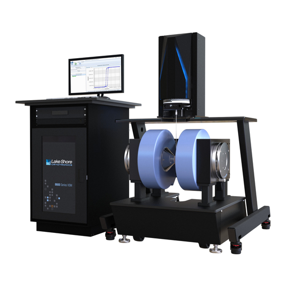
8600 Series
VSM System
Lake Shore Cryotronics, Inc.
575 McCorkle Blvd.
Westerville, Ohio
43082-8888 USA
sales@lakeshore.com
support@lakeshore.com
www.lakeshore.com
Fax: (614) 891-1392
Telephone: (614) 891-2243
Methods and apparatus disclosed and described herein have been developed solely on company funds of Lake Shore
Cryotronics, Inc. No government or other contractual support or relationship whatsoever has existed which in any
way affects or mitigates proprietary rights of Lake Shore Cryotronics, Inc. in these developments. Methods and
apparatus disclosed herein may be subject to U.S. Patents existing or applied for.
Lake Shore Cryotronics, Inc. reserves the right to add, improve, modify, or withdraw functions, design modifications,
or products at any time without notice. Lake Shore shall not be liable for errors contained herein or for incidental or
consequential damages in connection with furnishing, performance, or use of this material.
Revision 1.6
P/N 119-860
28 April 2022
|
www.lakeshore.com
Advertisement
Troubleshooting

Related Manuals for Lake Shore Cryotronics 8600 Series


Summary of Contents for Lake Shore Cryotronics 8600 Series
- Page 1 Cryotronics, Inc. No government or other contractual support or relationship whatsoever has existed which in any way affects or mitigates proprietary rights of Lake Shore Cryotronics, Inc. in these developments. Methods and apparatus disclosed herein may be subject to U.S. Patents existing or applied for.
- Page 2 Some countries, states or provinces do not allow lim- itations on an implied warranty, so the above limitation or exclu- Lake Shore Cryotronics, Inc. (“Lake Shore”) warrants that prod- sion might not apply to you. This limited warranty gives you ucts manufactured by Lake Shore (the “Product”) will be free...
- Page 3 Copyright 2018–2022 Lake Shore Cryotronics, Inc. All rights reserved. No portion of this manual may be system, or transmitted, in any form or by any means, electronic, mechanical, photocopying, recording, or otherwise, without the express written permission of Lake Shore.
- Page 4 EN 61326-1:2013 Class A, Controlled Electromagnetic Environment EN 55011:2009 Class A, Controlled Electromagnetic Environment EN IEC 63000:2018 Signed for and on behalf of: Place, Date: Westerville, OH USA Scott Ayer 08-FEB-2022 Director of Quality & Compliance 8600 Series VSM System...
- Page 5 To qualify for the CE Mark, the 8600 Series VSM system meets or exceeds the requirements of the European EMC Directive 2014/30/EU as a CLASS A product. A Class A product is allowed to radiate more RF than a Class B product and must include the following warning: WARNING:This is a Class A product.
- Page 6 8600 Series VSM System...
-
Page 7: Table Of Contents
1.2.3 8600 Series VSM System Software Features ........ - Page 8 3.4.2.4 Applying the Gases........... . 55 8600 Series VSM System...
- Page 9 3.4.3 Model 86-CRYO Variable Temperature Cryostat Option: Additional Setup ............. . .56 3.4.3.1 Making Connections .
- Page 10 5.4.5 Wiring Tables..............104 5.4.5.1 Wiring Tables for the 8600 Series Base System....104...
- Page 11 5.4.5.2 Wiring Tables for the 8600 Series Variable Temperature Options. 108 5.4.6 Wiring Diagrams ............110 5.5 Technical Inquiries .
- Page 12 C.6.2.1 Model 8610-CRYO Variable Temperature Cryostat Option ..165 C.6.2.2 Model 8610-OVEN High Temperature Oven Option ....168 8600 Series VSM System...
-
Page 13: Chapter 1: Introduction
Convenient operation The entire 8600 Series VSM system has been reimagined with a focus on clean, ergo- nomic design that simplifies the researcher’s interaction with the system. A motor- ized head brings the sample to a comfortable height for easy, one-handed exchange of the QuickLign™... -
Page 14: Materials And Measurements
VSM data collection process and interweave external process calls. The script window enables you to capture the predefined measurements to view as a script. This is useful for understanding exactly how the 8600 Series VSM system is 8600 Series VSM System... -
Page 15: Integrated Forc Data Acquisition
) and of switching fields (H 1.2.4 Accessories and The 8600 Series VSM system can be equipped with several temperature options to provide an environment for your sample that is suitable to your measuring needs. See Options section 2.3 and section C.3 for overviews of the options as well as the support struc- tures and instrumentation that can be added to your system to facilitate various measurements. -
Page 16: Technical Specifications
Full specifications about the 8600 series VSM are provided on our website. See: https://www.lakeshore.com/products/Vibrating-Sample-Magnetometer/8600-Series- Specifications VSM/pages/Specifications.aspx/ 1.4 System The site must be prepared before your new 8600 Series VSM system arrives. See Appendix B for site preparation information, and Chapter 3 and Appendix C Standard (Model 8610) for installation information. Equipment and Specifications 1.5 Safety... - Page 17 Do Not Substitute Parts or Modify System Components Do not install substitute parts or perform any unauthorized modification to the sys- tem. Return the instrument to an authorized Lake Shore Cryotronics, Inc. representa- tive for service and repair to ensure that safety features are maintained.
-
Page 18: Handling Liquid Helium And Liquid Nitrogen
Liquid helium (LHe) and liquid nitrogen (LN ) are used with Helium and Liquid the 8600 Series. Although not explosive, there are certain safety considerations for Nitrogen handling LHe and LN Operate all cryogenic containers (Dewars) in accordance with manufacturer instruc- tions. -
Page 19: Electrostatic Discharge
If exposure to cryogenic liquids or cold gases occurs, restore tissue to normal body temperature 37 °C (98.6°F) by bathing it in warm water not exceeding 40 °C (105 °F). Do not rub the frozen part, either before or after rewarming. Protect the injured tissue from further damage and infection and call a physician immediately. -
Page 20: Equipment Safety Symbols
Three-phase alternating current (power line) CAUTION or WARNING: See Earth (ground) terminal included documentation Protective conductor terminal CAUTION: Hot surface Frame or chassis terminal On (supply) CAUTION: Pinch point Off (supply) FIGURE 1-2 Safety symbols 8600 Series VSM System... -
Page 21: Chapter 2: System Overview
Chapter 2: System Overview 2.1 General Chapter 2 illustrates the 8600 Series VSM system major components, options and accessories. It also illustrates and establishes a vocabulary for the major components. Finally, it provides the basic theoretical concepts behind the system. -
Page 22: Measurement Platform
2.2.1.1 Electromagnet The electromagnet provides bipolar, variable DC magnetic field source in the standard 8600 Series VSM configuration. The Model 8604 and Model 8607 magnet’s ExactGap™ index setting can be changed easily to accommodate optional sample modules of different widths. The Model 8610 electromagnet provides a continuously variable gap with a gap setting tool. -
Page 23: Instrument Console
2.2.2.3 Computer and Monitor The 8600 Series VSM system is shipped with a Microsoft Windows® computer and a wide screen monitor. 2.2.2.4 System Software The system software is described in detail in the software manual for the 8600 Series VSM system. www.lakeshore.com... -
Page 24: Vsm Head Drive
2.2.4 X/Y/Z Adjustment The 8600 Series VSM system’s motorized z stage brings the sample to a comfortable height for easy exchange of sample rods. Rotation of the x-axis and y-axis are manually adjusted. -
Page 25: Configurations, Options, And Accessories: Model 8604 And Model 8607
2.3 Configurations, This section describes and illustrates the optional components of the Model 8604 and Model 8607 VSM systems. A wide selection of options make it possible to meet a Options, and variety of specific measurement applications. Accessories: Model 8604 and The GlideLOCK™... - Page 26 CHAPTER 2: System Overview FIGURE 2 -4 Transfer line details (dimensions in inches) 8600 Series VSM System...
-
Page 27: Model 86-Oven High Temperature Oven
2.3.2 Model 86-OVEN The high temperature oven enables the 8600 Series VSM to be used to investigate materials at high temperature. It consists of an electrically heated outer tube assem- High Temperature Oven bly with thermal insulation for sample-zone temperatures from 100 °C to 1000 °C with GlideLOCK™... -
Page 28: Model 86-Ssvt Single-Stage Variable Temperature Option
77 K to 950 K. Connect only 40 psi (276 kPa) clean nitrogen, argon, helium and compressed air to the gas controller. Higher pressure (>50 psi) can damage the gas controller. 8600 Series VSM System... -
Page 29: Quicklign™ Sample Rods And Holders
2.3.6 QuickLign™ The QuickLign™ sample rod system allows for precise, one-handed sample rod installation. Use sample rods with corresponding sample holders, or choose one of Sample Rods and the integrated rod/holders to meet your application needs. Holders FIGURE 2-7 QuickLign™ sample rod 2.3.7 General 2.3.7.1 Hall Probe A Model 86-0911 Hall probe, designed to mount onto the right half coil housing, is... -
Page 30: Theory Of Operation
(e.g. the Nickel standard) to calibrate the system and determine a moment per unit voltage calibration constant. After calibration, unknown samples can be measured in the same manner and quantified using the calibration constant determined during calibration. 8600 Series VSM System... -
Page 31: Chapter 3: Installation And Setup
Chapter 3: Installation and Setup 3.1 General This chapter describes unpacking the 8600 Series VSM system, verifying its subsystems, and assembling them into the standard configuration. Finally, it explains system checkout procedures. The 8600 Series VSM system was electrically and mechanically inspected and operationally tested prior to shipment. -
Page 32: Leveling: Model 8604 And Model 8607
GlideLOCK™ tray to check all four sides of the magnet. 6. Check the four wheels to confirm they are still all off the ground, spin freely, and are at least 3 mm (1/8 in) above the ground. The magnet will settle onto the 8600 Series VSM System... -
Page 33: Aligning The Isolation Frame
isolation donuts over the next 48 hours. Check that the magnet feet are parallel to the ground. FIGURE 3-1 Leveling Do not let the isolation frame touch the magnet. 3.2.2.3 Aligning the Isolation Frame Goal: To place the isolation frame in the correct position relative to the magnet with alignment pins. -
Page 34: Placing The Vsm Head On The Isolation Frame
3. Confirm there is a 3 to 6 mm (1/8 to 1/4 in) gap between the VSM head and the isolation frame. 4. Remove the two handles from the sides of the VSM head, along with the two screws on the sides of the lower portion of the back cover. 8600 Series VSM System... - Page 35 5. Take the back cover off the VSM head. The back cover is designed to be tight-fitting. If the back cover will not lift off easily, use a small side-to-side motion until it starts moving. 6. Remove the shipping screw by removing the retaining screw (4 mm Allen key) on the right side and turning the retaining bar counter-clockwise until the all- thread screw is removed.
-
Page 36: Initial Adjustment Of The Tip/Tilt Of The Z Translation Stage
3. Open the VSM software. If the instrumentation in the console is not turned on, an error message will appear. The software, however, will still rotate and raise/lower the head. 8600 Series VSM System... - Page 37 4. In the Monitor window, there are options to rotate and raise/lower the head. If the Z position is “????” click Home to raise the head to the Home position. This will allow the software to index the position of the head. FIGURE 3-5 Head position 5.
-
Page 38: Checking The Rotation Stage
The side screws can only be reached when the head is raised to the Home position. The screws require a 3 mm Allen key. Two people are required to lift the VSM head cover. 8600 Series VSM System... - Page 39 8. When removing the front head cover, unplug the cable on top of the head. The cable allows for the front head cover to be moved a maximum of 152 mm (6 in). FIGURE 3-8 Head cover removal 9. There are three fine adjustment screws on the rotation stage located every 120 degrees.
-
Page 40: Initial Adjustment Of The Tip/Tilt Of The Vsm Head
FIGURE 3-10 Metal reference rod 3. Move the head from 160 mm to 0 mm, monitoring any left/right motion. Adjust the right or left adjustment screws on the VSM head until this motion is within 0.5mm (1/32 in). 8600 Series VSM System... -
Page 41: Final Adjustment Of The Tip/Tilt Of The Z Translation Stage
If you lower the head and the metal reference rod moves to the right, the VSM head is low on the left side. To adjust, raise the left adjustment screw. FIGURE 3-11 Adjustment screw 4. See if the head rocks forward or backward and if it does, raise the front or back adjustment screw until it touches the VSM head. -
Page 42: Final Adjustment Of The Tip/Tilt Of The Vsm Head
7. Adjust any movement off center using the four adjustment screws under the VSM head. If you lower the head and the metal reference rod moves forward, the VSM head is low on the back side. To adjust, raise the back adjustment screw. 8600 Series VSM System... -
Page 43: Final Check
If you lower the head and the metal reference rod moves to the right, the VSM head is low on the left side. To adjust, raise the left adjustment screw. 8. Repeat steps 6 and 7 until the metal reference rod stays roughly centered throughout the travel from 320 mm to 0 mm. -
Page 44: Power Requirements
CHAPTER 3: Installation and Setup 3.2.3 Power The AC power source connected to the 8600 Series VSM system must be frequency- and voltage-regulated, and isolated from sources that may generate electromagnetic Requirements interference (EMI). Ground fault interrupter (GFI) and transient surge protection circuitry at the AC source are also strongly recommended. -
Page 45: Water Requirements
Both the electromagnet and power supply require access to cooling water. Refer to TABLE B-4 and TABLE B-5. Requirements 3.2.5 Cryogen The 8600 Series VSM system options use liquid helium (LHe) and liquid nitrogen ). Refer to the table below. Requirements Option... -
Page 46: Gas Requirements
Model 705 TABLE 3-4 Gas requirements Tipping compressed gas cylinders must be anchored properly before use. Tipping cylinders can cause serious injury or death. Follow local safety regulations to properly secure cylinders. Requirements by country may vary. 8600 Series VSM System... -
Page 47: Making Connections
3.3 Making Follow the instructions below to make the connections. Connections Make sure to check supply voltage before making connections. 3.3.1 Cooling Water Provided proper flow and temperature are maintained, standard municipal water systems are generally suitable to cool the magnet and power supply. Do not use Connections deionized water if you are using closed loop cooling, as this may corrode the copper tubing in the system. -
Page 48: Flow Switch
Fault indication due to flow is instantaneous (no delay). Use a water line unaffected by pressure variations FIGURE 3-13 Flow switch for the 4-in and 7-in magnets FIGURE 3-14 Flow switch for the 10-in magnet 8600 Series VSM System... -
Page 49: Power Supply Cooling Water
3.3.1.3 Power Supply Cooling Water Supply and return water supply lines are required to cool the magnet power supply. The water connections for the Model 648 magnet power supply are 12.5 mm (½ in) hose barb fittings, and water connections for the Model 643 magnet power supply are 9.5 mm (3/8 in). -
Page 50: Instrument Console Connections
Allows communication to the PC. Connects to the USB hub in the instrument console. Line input assembly Power is provided to the Model 737 through the line input assembly. TABLE 3-5 Model 737 connections 8600 Series VSM System... -
Page 51: Model 336 Temperature Controller Connections
3.3.2.2 Model 336 Temperature Controller Connections Rear panel connections for the Model 336 temperature controller are shown in the figure below. For more details, see the Model 336 user’s manual. The Model 336 temperature controller is an optional item, but is required for all temperature options. -
Page 52: Model 142 Amplifier Connections
Model 737 rear panel. Gain Sets the amplifier’s gain. Select x10 for both switches. Sets the amplifier into stereo mode. The amplifier should be set to stereo Stereo (where applicable) mode. TABLE 3-7 Model 142 connections 8600 Series VSM System... -
Page 53: Model 705 Gas Controller Connections
3.3.2.4 Model 705 Gas Controller Connections Rear panel connections for the Model 705 gas controller are shown below. Insert inlet and outlet gas hoses to the Model 705 gas controller in the instrument console, if this was not completed at Lake Shore. In general, shorter gas hoses provide lower pressure drop and better flow. -
Page 54: Computer Connections
Do not install any third-party software on this computer. Installing other software may cause conflicts with the operation of the 8600 Series VSM system and can have unintended consequences. Lake Shore assumes no responsibility for damage to the system as the result of unauthorized software installation. -
Page 55: Magnet/Vsm Drive Electrical Connections
3.3.3 Magnet/VSM This section details electrical connections from the electromagnet and VSM drive. Magnets are wired to match the output of the power supply. In general, the VSM Drive Electrical magnet is wired to a nominal resistance of 0.5 . However, the magnets and power Connections supplies may look different. -
Page 56: 10-Inch Electromagnet Connections
3. The water flow interlock switch and thermal over-temperature switches are pre- wired to the terminal block. The cable from the power supply interlock connection runs to Pins 1 and 4 on the terminal block. FIGURE 3-24 Electrical connections for a 10-in magnet (cover removed) 8600 Series VSM System... -
Page 57: Vsm Head Drive Connections
3.3.3.3 VSM Head Drive Connections The standard VSM head drive has three connections: a USB connector, a D-sub type connector, and a large circular main connector. See the figure below. 1. The main uses a large circular connector. 2. A 9-pin D-sub cable is connected to the motor controller power supply mounted in the instrument console. -
Page 58: Vsm Pick-Up Coils And Connections
4. Identify the face of the coil set that has the raised section for the cable entry. This surface goes against the pole cap face. 5. Orient the left coil set half against the left pole cap face with the cable facing down and back at 45°. 8600 Series VSM System... - Page 59 6. Rotate the coil slightly so that the two larger openings in the coil are aligned with the two brass screws, and place the coil set against the pole face. 7. Rotate the coil so that the brass screws align with the countersink holes in the coil set.
-
Page 60: Head Leveling/Alignment
JUNCTION BOX FIGURE 3-28 Coil wiring diagram 3.3.5 Head Leveling/ The 8600 Series VSM system’s motorized head brings the sample to a comfortable height for easy exchange of sample rods. The QuickLign™ quick-release coupling Alignment mechanism allows the rod to slide smoothly into the measurement collar and lock securely in place —... -
Page 61: Gaussmeter Probe Holder Installation
3.3.6 Gaussmeter Mount the gaussmeter probe to slot in the right coil on the right pole cap, as shown below. Probe Holder Installation Always turn off the magnet power supply when installing or removing options, changing vector coils, installing Hall probes, or adjusting the magnet gap. Injury may occur. Exercise care when handling the gaussmeter probe;... -
Page 62: Changing Probes
For best results, the instrument and probe should warm up for at least 5 min before zeroing the probe and at least 30 min for rated accuracy. The probe and the zero gauss chamber should be at the same temperature. 8600 Series VSM System... -
Page 63: Magnet Power Supply Connections
3.3.7 Magnet Power Although different models of power supply are used, they have similar wiring connections. Per the site preparation instructions (Appendix B), the user is Supply Connections responsible for providing the hookup from the electrical box at back of the power supply to the electrical source. -
Page 64: Model 648 Electrical Connections
Power supply inhibit connector. It is connected to a single water flow and Magnet flow switch two thermal cutoff switches in series, any of which can inhibit the output of the power supply. TABLE 3-12 Model 648 connections 8600 Series VSM System... -
Page 65: Installing The Options: Model 8604 And Model 8607
4.6.1 to change the setting if necessary. 2. If the magnet index setting or pole caps have changed, be sure to change the sys- tem configuration in the 8600 Series system software to reflect any changes made to the hardware configuration. - Page 66 Refer to the following table for the ExactGap™ magnet index settings for the options. ExactGap™ Option Pick-up coil set Gap tool setting magnet index setting Model 86-CRYO Model 86-LC oven/cryostat Model 86-OVEN Model 86-LC oven/cryostat Model 86-SSVT Model 86-LC SSVT TABLE 3-13 ExactGap™ magnet index settings 8600 Series VSM System...
-
Page 67: Model 86-Ssvt Single-Stage Variable Temperature Option
3.4.2 Model 86-SSVT After installing the temperature option into the GlideLOCK™ mount, follow these additional instructions if you are using the Model 86-SSVT single-stage variable Single-Stage Variable temperature (SSVT) option. A list of equipment needed to install and set up the Temperature Option: Model 86-SSVT option is listed in section B.3.6. -
Page 68: Model 86-Cryo Variable Temperature Cryostat Option
2. Leave the pump on for 30 min before cooling. If you are using an oil sealed vacuum pump, close the pump-out valve before cooling. 3.4.3.3 Verifying the Noise-Free System 1. Verify the calibration. 2. Check the moment noise at 0° operating angle. 3. Check the moment noise during a sample rotation. 8600 Series VSM System... -
Page 69: Model 86-Oven High Temperature Oven Option
3.4.4 Model 86-OVEN After installing the temperature option into the GlideLOCK™ mount, follow these additional instructions if you are using the Model 86-OVEN oven option. A list of High Temperature Oven equipment needed to install and set up the Model 86-OVEN option is listed in Option: Additional section B.3.6. -
Page 70: Flow Meter Assembly
If you do not have the Model 705 gas controller, a flow meter is required. Mount the flow meter on a wall next to the gas supply. Connect 5 psi to 10 psi (34.5 kPa to 69 kPa) argon gas supply line to the flow meter. FIGURE 3-37 Flow meter assembly 8600 Series VSM System... -
Page 71: Model 86-Vec Vector Coils Option Setup
3.4.5 Model 86-VEC Follow these instructions to install the Model 86-VEC vector coils option. Vector Coils Option Refer to section 4.6 for the procedure to change the magnet gap. Setup Always set the current to zero and turn off the power supply before attempting to adjust the magnet gap To install the vector coils: 1. - Page 72 CHAPTER 3: Installation and Setup FIGURE3-38 Left: Model 86-VEC vector coils option; Right: Model 86-VEC vector coils option installed 8600 Series VSM System...
-
Page 73: General
This chapter describes the majority of daily hardware operation. The system software is described in detail in the Software Manual for the 8600 Series VSM. This chapter assumes that the system has been installed and set up as described in Chapter 3. -
Page 74: Operating The Standard System Hardware
4.6.1 to change the setting if necessary. 4. If the magnet index setting or pole caps have changed, calibrate the system, or use one of the previously stored calibrations in the 8600 Series system software. 5. Raise the head. -
Page 75: Electrical Connections
4.3.1.2 Electrical Connections Power and temperature connections are automatically engaged when the GlideLOCK™ tray is mounted and slides back into the magnet. Make sure that the connector is securely snapped into the connection behind the mount. FIGURE 4-2 Electrical connection www.lakeshore.com... -
Page 76: Avoiding Water Condensation
If the air temperature is 24 °C (75 °F) and the relative humidity is 35%, the intersection of the two shows a dew point of 7 °C (45 °F). Therefore, for the given conditions, the cooling water must remain above 7 °C (45 °F) to prevent condensation. 8600 Series VSM System... -
Page 77: Mounting A Sample
4.5 Mounting a The 8600 Series VSM system uses a variety of QuickLign™ sample rods/holders for use with most sample types. Use sample rods and corresponding sample holders, or Sample choose one of the single piece, integrated sample rod/holders to meet your application needs. - Page 78 730935 Liquid disposable cup Kel-F® 86-SH-0840 Gel cap straw mount Kel-F® 86-SH-0841 Disposable gel caps and straws (1000 count)* Gelatin * Room temperature only TABLE 4-3 Sample holders for 86-SR-0935 FIGURE 4-7 Sample rods for 86-SR-0935 8600 Series VSM System...
-
Page 79: High Temperature Application Sample Rods And Holders
4.5.1.2 High Temperature Application Sample Rods and Holders The high temperature sample holders used with the 8600 Series VSM system are made of boron nitride, or fused quartz. Boron nitride offers the unique combination of physical and mechanical properties and a moderate magnetic signature. These characteristics are difficult to find in other materials with a 1000 °C service ceiling. -
Page 80: Single Piece Integrated Sample Rods And Holders
2. Start with an inner piece of #4 gel cap, and drop in a small amount of sample material. 3. Insert an outer piece of a #5 gel cap onto the inner #4 piece as shown, with both curved surfaces in the same direction (unlike a traditional gel cap holding medi- 8600 Series VSM System... -
Page 81: Thin-Film Sample Holders
cine). Gently force it into position. It should be a snug fit, holding the sample in place. 4. Slip the #4 inner piece of the gel cap onto the lower portion of the Kel-F® adapter, as shown. #5 outer piece #4 inner piece Powder sample FIGURE 4-11 Gel sample holder... - Page 82 Never place your hands or other body parts in the pat of the moving VSM head. Injury may result. To prevent damaging the sample holder, remove the rod and holder before changing the sample holder or sample. FIGURE 4-12 Sample rod installation FIGURE 4-13 Micrometer controls 8600 Series VSM System...
-
Page 83: Installing A Sample Rod (Variable Temperature)
4.5.1.9 Installing a Sample Rod (Variable Temperature) Follow the steps below to mount a sample rod. Keep the sample rod/holder perpendicular when attaching to the drive. Excess torque on the sample rod/holder will damage the rod and alignment of the drive. 1. -
Page 84: Sample Saddling
Z-axis. If your system displays a double peak, then Z-axis saddling is to the minimum point between the two peaks as shown in FIGURE 4-15. FIGURE 4-15 Double peak Z-axis saddling 8600 Series VSM System... -
Page 85: Sample Rod Rotation Adjustment
4.5.3 Sample Rod The autorotation feature offers full software-based control over sample rotation about the Z-axis. The sample can be continuously rotated in either the clockwise or Rotation Adjustment counter-clockwise direction. Most sample rods are aligned sufficiently at the factory for general case, non-rotation measurements. - Page 86 180° from this position. If not, repeat steps 8 and 9. 11. Repeat steps 4 through 10 until the desired sample variation is obtained, typi- cally, less than a ± 1% error in moment during rotation. 8600 Series VSM System...
-
Page 87: Operating The Magnet Hardware
4.6 Operating the This section explains procedures that are specific to the magnet hardware. The introduction to each section explains when or in what circumstance you need to Magnet Hardware perform the action. Always turn off the magnet power supply when installing or removing options, changing vector coils, installing Hall probes, or adjusting the magnet gap. - Page 88 Right: Push in the pole adjustment plate; there will now be a gap between the plate and the ring (the gap is indicated by the arrow in this picture). 9. Using a 8 mm hex driver, tighten all four screws on the pole adjustment plate. 8600 Series VSM System...
-
Page 89: Index Setting
10. Repeat steps 1 through 9 for the opposite magnet pole. Be aware that the adjust- ment plate on the opposite magnet pole will move in the opposite direction from the first. 4.6.1.2 Preparing the System for Use After Changing the Magnet Index Setting After changing the setting, you can install the selected option, turn on the electromagnet power supply, and start up the system (section 4.2.1). -
Page 90: Installing The Pole Caps
(section 4.2.1). After performing these functions, be sure to change the system configuration in the 8600 Series system software to reflect any changes made to the hardware configuration. 8600 Series VSM System... -
Page 91: Basic Operation Of The Options: Model 8604 And Model 8607
4.7 Basic The following sections provide operation instructions for the temperature options for the Model 8604 and Model 8607 VSM systems. Operation of the Options: Model 8604 and Model 8607 Temperature options used with the Model 8610 are used differently. For more details, please see section C.6.2 of this manual. -
Page 92: Warm Up Sample Space And Condenser
The curve is in location 27. The proper domains will be set when the VSM software starts. The values in the table below are default domains for the temperature options. They are set by the software, and therefore, are for informational purposes only. 8600 Series VSM System... -
Page 93: Temperature Option
Temperature Ramp rate Settle band/ Zone Power range range (K) (K/min) time 70 – 79 5 / 2 79 – 115 5 / 4 115 – 200 High 1 / 2 200 – 320 High 1 / 2 320 – 775 High 1 / 2 775 –... -
Page 94: Cool Down
This should be done while the inner line is at room temperature. Helium gas and moist air should never be allowed inside these spaces. For normal operation, pump the 8600 Series VSM System... - Page 95 line vacuum space overnight every three months to avoid condensation/ice on the transfer line or SSVT body inlet when operating at low temperature. 3. Prevent air in the gas line by keeping the line connected to the Model 705 gas controller and condenser at all times.
-
Page 96: Model 86-Cryo Variable Temperature Cryostat Option
0.5 / 5 135 – 175 High 1 / 5 175 – 250 High 1 / 5 250 – 350 High 1 / 5 350 – 450 High 2 / 10 TABLE 4-10 Cryostat temperature domains for nitrogen 8600 Series VSM System... -
Page 97: Operating The Model 86-Cryo Cryostat Option
The helium curve is in location 23 and the nitrogen curve is in location 24. The proper domains will be set when the VSM software starts. If this option was ordered with the VSM system, sensor curves 23 and 24 were loaded into the temperature controller at Lake Shore for reading and controlling the sample temperature. -
Page 98: Cool Down
2. It is preferable to maintain a vacuum in the flexible line vacuum space and cryo- stat vacuum space at all times. Evacuate the cryostat prior to each use. Evacua- 8600 Series VSM System... - Page 99 tion should be done while the inner space is at room temperature. The transfer line will need to be evacuated periodically with a turbomolecular pumping sta- tion. This should be done while the inner line is at room temperature. Helium gas and moist air should never be allowed inside these spaces.
-
Page 100: Model 86-Oven High Temperature Oven Option
Argon gas is a potential asphyxiant and can cause rapid suffocation without warning. Use only in an adequately ventilated area. DO NOT vent or use in confined spaces. Follow Compress Gas Association (CGA) best practices, applicable safety data sheet (SDS) and applicable local safety requirement. 8600 Series VSM System... -
Page 101: Model 86-Oven Operation Overview
FIGURE 4-25 Heating and cooling curves 4.7.3.1 Model 86-OVEN Operation Overview High temperature oven operation is straightforward. A special high temperature sample holder replaces the standard sample holder. After establishing the required vacuum, begin operation at elevated temperatures. There is no need to cool the oven to change the sample. -
Page 102: Other Oven Information
50% concentrated nitric acid suffices. FIGURE 4-26 Boron nitride sample holder 4.7.3.2.3 Storage Store the oven in any position. Seal the vacuum tube to minimize moisture absorption by the ceramic heater insulation. This causes outgassing on subsequent heating. 8600 Series VSM System... - Page 103 4.7.3.2.4 Heater Temperature versus Sample Zone Temperature It is important to distinguish between heater temperature and sample zone temperature. The supplied internal thermocouple monitors the heater temperature. Changes in sample zone temperature always lag changes in heater temperature. This may be important in some experiments. FIGURE 4-27 shows a plot of sample zone temperature versus heater temperature for an instrumented oven with a thermocouple installed inside the sample holder.
-
Page 104: Model 86-Vec Vector Coils Option
Calibrate Y-axis coils with a permanent magnet at an applied field of zero gauss: 1. Select the Y-axis calibration from the 8600 Series system software menu to fol- low the automated calibration process. The magnetization axis of the permanent magnet rotates –90° according to the rotation index on the VSM drive head. -
Page 105: General
Chapter 5: Maintenance and Troubleshooting 5.1 General This chapter covers maintenance, troubleshooting and field service instructions. Customer service of the product is limited to the information presented in this chapter. Lake Shore personnel should be consulted if the instrument requires repair. Instructions for contacting Lake Shore and arranging product service are in section 5.5. -
Page 106: Cleaning The Sample Holders
Drain any coolant from the cooling lines. Additionally, use air pressure to force out any remaining water from the internal coil cooling lines. Desiccant packs may be stored with the magnet to reduce effects from a moist storage environment. 8600 Series VSM System... -
Page 107: Electromagnet Power Supply Maintenance
Do not over-tighten the fasteners. Fasteners should be snug, but do not over-tighten, particularly those securing the brace to the coil halves. 5.2.9 Calibration Calibration is set in the 8600 Series system software. Contact Lake Shore for training and information on calibration. www.lakeshore.com... -
Page 108: Troubleshooting Procedures
Place the ohmmeter test leads between pin 1 and 2. Confirm open contact (since the water is off). Turn the water on, and confirm open contact with the ohmmeter test leads between pin 1 and 2. 8600 Series VSM System... - Page 109 4. When the water is on and sufficient flow exists as indicated by the flow meter, but the ohmmeter registers an OPEN contact, you must troubleshoot this condi- tion. The following conditions which may be at fault: The magnet power supply interlock wiring has failed The water flow switch has failed The coil is overheated The coil over-temperature switch has failed...
-
Page 110: Vacuum Troubleshooting
CHAPTER 5: Maintenance and Troubleshooting 5.3.2 Vacuum The 8600 Series VSM system should be able to achieve a vacuum of <10 Torr at room temperature with an appropriate vacuum system and the gauge located on the Troubleshooting pump. For vacuum requirements, see section 3.2.6. -
Page 111: General Troubleshooting
4. Close the vacuum isolation valve; in this step we are only checking the vacuum of the connection up to the system. 5. Power on the pumping system. 6. Observe the vacuum gauge reading. If the connections are all made securely, the read- ing should come down to <10 Torr within 10 min of pumping. -
Page 112: Troubleshooting The Options
Note the readings on the VSM software Monitor window. If the sample sensor shows Error or Fault, this indicates there is an error in the sample insert. If the Primary Loop shows “Temperature error” this indicates there is a sensor failure in the body. 8600 Series VSM System... -
Page 113: Option Troubleshooting
5.3.4.3 Model 86-SSVT Single-Stage Variable Temperature Option Troubleshooting The vacuum space of the transfer line should be re-evacuated when the outer surface feels cold during operation. Under normal operation, the line should be pumped quarterly. A good pumping station (e.g., a turbo pump), capable of bringing the ultimate pressure down to approximately 10 –5 Torr, is recommended. -
Page 114: Service Reference
A protective earth terminal is present on the electronic console rear rack mounting rail. Do not disturb or remove any wires connected to this terminal. 8600 Series VSM System... -
Page 115: Electrostatic Discharge
5.4.3 Electrostatic Electrostatic discharge (ESD) may damage electronic parts, assemblies, and equip- ment. ESD is a transfer of electrostatic charge between bodies at different electro- Discharge static potentials caused by direct contact or induced by an electrostatic field. The low-energy source that most commonly destroys electrostatic discharge sensitive devices is the human body, which generates and retains static electricity. -
Page 116: Wiring Tables
CHAPTER 5: Maintenance and Troubleshooting 5.4.5 Wiring Tables This section provides the wiring diagrams and tables for the various components and options in the 8600 Series VSM system. 5.4.5.1 Wiring Tables for the 8600 Series Base System Console connector Function Head connector... - Page 117 Console connector Function Junction box connector Gradient drive- Model 737 Junction box AGM drive AGM drive Gradient drive+ D-sub 9-pin 3-pin DIN Ground Hall probe+ Hall temperature sense V+ Hall temperature sense I+ Hall temperature sense I- Hall temperature sense V- Ground Model 737 Junction box...
- Page 118 142 connector VSM drive- Model 142 Input 1 Model 737 VSM drive+ XLR 3-pin head drive Signal B- Model 142 terminal block 4-pin Input 2 Signal B+ XLR 3-pin TABLE 5-11 Head drive cables (inside console) 8600 Series VSM System...
- Page 119 737 connector Function Magnet power supply connector Program+ Model 737 Model 643/648 * Program- program voltage analog I/O Drain wire D-sub 9-pin D-sub 15-pin NOT USED 1, 2, 4-10, 12-15 * The Model 643 and Model 648 have the same cable pin out; only the length is different. TABLE 5-12 Program voltage cables (Model 737 to magnet power supply) Magnet connector Function...
-
Page 120: Wiring Tables For The 8600 Series Variable Temperature Options
CHAPTER 5: Maintenance and Troubleshooting 5.4.5.2 Wiring Tables for the 8600 Series Variable Temperature Options Console connector Function Option connector* Pin* Input A I- Input A V- Model 336 Input A shield Input A Input A V+ 6-pin DIN Input A I+ NOT USED —... - Page 121 Option back connector Function Option front connector** Pin** Vector Y EMU+ Vector Y shield Vector Y balance+ Vector Y D-sub 9-pin Vector Y EMU- Vector Y balance- 3, 4, 7, 8 NOT USED — Input A I+ Input A V+ Input A shield Input B I+ Input B V+...
-
Page 122: Wiring Diagrams
3, 4, 7, 8 NOT USED 3, 4, 7, 8 TABLE 5-21 Variable temperature option cables—Model 86-VEC option cables 5.4.6 Wiring Diagrams The wiring diagrams for the 8600 Series VSM system are provided on the following pages. 8600 Series VSM System... - Page 123 86-LC PICK-UP REAR VIEW Hall COILS RIGHT X COIL LEFT X COIL probe To connectors on VT option HALL PROBE VECTOR Y LEFT COIL RIGHT COIL GAUSSMETER EMU X AGM DRIVE EMU Y FIGURE 5-3 8600 Series VSM system wiring www.lakeshore.com...
- Page 124 86-OVEN: TO GLIDELOCK™ INTERFACE Reference section 5.4.5 for pin out tables 8610-OVEN: L1 4-pin connector/cable to Model 336 OVEN BODY L1 HEATER — 27 L1 CONTROL SENSOR — TYPE K T/C (2) FIGURE 5-4 8600 Series VSM system wiring 8600 Series VSM System...
- Page 125 LIQUID He CRYOGEN WATER SUPPLY SOURCE VACUUM WATER RETURN SOURCE 1 PH AC INPUT + GND Chiller (option)—available from Lake Shore WATER CHILLER SUPPLY WATER RETURN 1/3 PH AC INPUT + GND FIGURE 5-5 8600 Series VSM system wiring www.lakeshore.com...
-
Page 126: Technical Inquiries
Lake Shore within 30 days after the RMA has been issued. You will be contacted if we do not receive the equipment within 30 days after the RMA is issued. The RMA will be canceled if we do not receive the equipment after 60 days. 8600 Series VSM System... -
Page 127: Shipping Charges
5.5.4 Shipping Charges All shipments to Lake Shore are to be made prepaid by the customer. Equipment serviced under warranty will also be returned shipping prepaid by the customer. Equipment serviced out-of-warranty will be returned FOB Lake Shore. 5.5.5 Restocking Fee Lake Shore reserves the right to charge a restocking fee for items returned for exchange or reimbursement. - Page 128 CHAPTER 5: Maintenance and Troubleshooting 8600 Series VSM System...
-
Page 129: Appendix A: Glossary Of Terminology
Appendix A: Glossary of Terminology A.1 General accuracy. The degree of correctness with which a measured value agrees with the true value. electronic accuracy. The accuracy of an instrument independent of the sensor. sensor accuracy. The accuracy of a temperature sensor and its associated calibration or its ability to match a standard curve. - Page 130 A system in which the basic units are the centimeter, gram, and second. coercive force (coercive field). The magnetic field strength (H) required to reduce the magnetic induction (B) in a magnetic material to zero. 8600 Series VSM System...
- Page 131 coercivity. generally used to designate the magnetic field strength (H) required to reduce the magnetic induction (B) in a magnetic material to zero from saturation. The coercivity would be the upper limit to the coercive force. compliance voltage. See current source. Curie temperature (Tc).
- Page 132 Hall mobility. The quantity µH in the relation µH = R, where R = Hall coefficient and = conductivity. hazard communication standard (HCS). The OSHA standard cited in 29 CFR 1910.1200 requiring communication of risks from hazardous substances to workers in regulated facilities. 8600 Series VSM System...
- Page 133 Helmholtz coils. A pair of flat, circular coils having equal numbers of turns and equal diameters, arranged with a common axis, and connected in series; used to obtain a magnetic field more nearly uniform than that of a single coil. hertz (Hz).
- Page 134 Gaithersburg, Maryland and Boulder, Colorado, that defines measurement standards in the United States. negative temperature coefficient (NTC). Refers to the sign of the temperature sensitivity. For example, the resistance of a NTC sensor decreases with increasing temperature. 8600 Series VSM System...
- Page 135 noise (electrical). Unwanted electrical signals that produce undesirable effects in circuits of control systems in which they occur. normalized sensitivity. For resistors, signal sensitivity (dR/dT) is geometry dependent; i.e., dR/dT scales directly with R; consequently, very often this sensitivity is normalized by dividing by the measured resistance to give a sensitivity, s , in percent change per kelvin.
- Page 136 SI susceptibility. See also initial susceptibility and differential susceptibility. As in the case of magnetization, the susceptibility is often seen expressed as a mass susceptibility or a molar susceptibility depending upon how M is expressed. 8600 Series VSM System...
- Page 137 temperature scales. See Kelvin Scale, Celsius Scale, and ITS-90. Proper metric usage requires that only kelvin and degrees Celsius be used. However, since degrees Fahrenheit is in such common use, all three scales are delineated as follows: D To convert kelvin to Celsius, subtract 273.15. D To convert Celsius to Fahrenheit: multiply °C by 1.8 then add 32, or: °F = (1.8 ×...
- Page 138 Appendix A: Glossary of Terminology 8600 Series VSM System...
-
Page 139: Appendix B: Site Preparation
Site Preparation The customer is responsible for all site preparations preceding installation of the 8600 Series VSM System. The following is a summary of the preparations that must Site Requirements be completed before the arrival of the Lake Shore engineer. Travel arrangements cannot be finalized until the customer acknowledges that the site is ready by signing the provided “Acceptance of Site Preparation”... -
Page 140: Unpacking The System
Note how the console was supported on the pallet for future reference. Foam blocks between the instruments support their weight during shipment. If you need to transport the unit, leave them in place. 8600 Series VSM System... -
Page 141: Unpacking The Options: Model 8604 And Model 8607
B.2.4 Unpacking the Follow these instructions to unpack each option for the Model 8604 and Model 8607 VSM systems. After removal of the protective padding and shipping supports, each Options: option should be visually inspected for any damage incurred during shipment. Report Model 8604 and any visible damage to the crate or option to your shipping/receiving department, and Model 8607... -
Page 142: Unpacking The Options: Model 8610
91 cm × 117 cm × 122 cm Power supply Included in the instrument console (36 in × 46 in × 48 in) 281 kg (620 lb) TABLE B-1 Model 8604 and Model 8607 standard system shipping container size and weight 8600 Series VSM System... - Page 143 Model 8610 1928 kg (4250 lb) Electromagnet 107 cm x 107 cm x 114 cm (42 in x 42 in x 45 in) 176 kg (388 lb) Electromagnet base 112 cm x 112 cm x 43 cm (44 in x 44 in x 17 in) 127 kg (279 lb) Isolation frame 122 cm x 91 cm x 132 cm...
-
Page 144: Space Requirements And Suggested Layout
8607: 1845 lb (837 kg) Customer-supplied items are in orange: 8610: 4300 lb (1950 kg) must be prepared prior to training Optional equipment indicated by dotted outlines FIGURE B-2 8600 Series VSM system primary floor plan 8600 Series VSM System... -
Page 145: Location
8610: 4300 lb (1950 kg) must be prepared prior to training Optional equipment indicated by dotted outlines FIGURE B-3 8600 Series VSM system alternate floor plan B.3.1 Location To meet and maintain specifications, operate the system at an ambient temperature range of 18 °C to 28 °C (64.4 °F to 82.4 °F). -
Page 146: Structural Integrity
11.4 L/min (3 gal/m) 15 L/min (4 gal/m) * The electromagnet is equipped with a flow switch that inhabits the power supply output if the water flow falls below this specification. TABLE B-4 Electromagnet cooling water requirements 8600 Series VSM System... -
Page 147: Power Supply Site Preparation
B.3.5 Power Supply Site The power supply requires one water supply line and one return line for cooling. The water connections for the Model 648 magnet power supply are 12.7 mm (½ in) hose Preparation barb fittings, and water connections for the Model 643 magnet power supply are 9.5 mm (3/8 in). -
Page 148: Site Preparation For The Options: Model 8604 And Model 8607
Dewar Clean compressed air (40 psi [276 kPa]) Vacuum pump. For vacuum requirements, see section 3.2.6. A Pirani or thermocouple vacuum gauge capable of measuring pressures from 0.1 to 100 Pa (10 to 1 Torr) 8600 Series VSM System... -
Page 149: Model 86-Cryo Variable Temperature Cryostat Option
B.3.6.2 Model 86-CRYO Variable Temperature Cryostat Option B.3.6.2.1 Equipment Included with the Cryostat Option Combination LHe/LN cryostat with GlideLOCK™ mount LHe/LN transfer line Cryogen transfer kit Sample rods and holders Wall mount bracket to store option when not in use 2 m (79 in) vacuum hose to connect the option to the vacuum source. -
Page 150: Site Preparation For The Options: Model 8610
25 psi pressure setting, a 10 psi relief valve with a 3/8 male NPT thread and an adaptor coupling to a 1/4 male NPT thread are provided for the change over. In these cases, the Dewar manufacturer must be consulted before any modifications are undertaken by the customer. 8600 Series VSM System... -
Page 151: Model 8610-Oven High Temperature Oven Option
B.3.7.1.1 Equipment Included with the Cryostat Option Combination LHe/LN cryostat with mount LHe/LN transfer line Cryogen transfer kit Instrument cables and related accessories Sample rods and holders 2 m (79 in) vacuum hose to connect the option to the vacuum source. To maintain a good vacuum, the length of the vacuum hose should be as short as possible. - Page 152 Appendix B: Site Preparation 8600 Series VSM System...
-
Page 153: Overview
Appendix C: Model 8610 System C.1 Overview The following information is specific to the Model 8610 vibrating sample magnetom- eters (VSM) system. C.2 System The measurement platform provides the magnetic field and serves as the support for the sample management components. Major components of the measurement plat- Overview form include the electromagnet, isolation frame, and VSM head. -
Page 154: Options And Accessories: Model 8610
The cryostat design provides the user the capability to perform measurements eco- nomically over nearly the entire accessible temperature range with a single cryostat. The transfer line is included with the cryostat. FIGURE C-2 Model 8610-CRYO cryostat 8600 Series VSM System... - Page 155 FIGURE C-3 Model 8610-CRYO transfer line details www.lakeshore.com...
-
Page 156: Model 8610-Oven High Temperature Oven
At room temperature and above, measurements may be performed on samples con- tained in an argon atmosphere to protect the sample from oxidation. FIGURE C-4 Model 8610-OVEN high temperature oven 8600 Series VSM System... -
Page 157: Model X-Mr Magnetoresistance (Mr) Probe Option
C.3.3 Model X-MR The MR probe option performs fast and accurate measurements of MR, GMR spin- valve, CMR and other magnetoresistive materials as a function of both in-plane mag- Magnetoresistance netic field and temperature. This measurement option includes data acquisition, con- (MR) Probe Option trol, and analysis software to automatically extract pertinent parameters for the device under test. -
Page 158: Model 8610-Vta Temperature Option Kit
The refrigeration system uses a hermetically sealed compressor and hot gas bypass system of temperature control. This system eliminates on/off cycling and premature wear of the compressor. Strong pumps provide continuous flow even through cooling lines with small IDs. 8600 Series VSM System... -
Page 159: Leveling
C.4 Leveling C.4.1 Required Tools Level Ruler 24 mm wrench 13 mm wrench Laser Clear alignment target Magnet gap tool Temperature options 10 in sample rod C.4.2 Leveling the Goal: The magnet, frame, and VSM drive need to be level for best performance. Magnet Platform: Use a standard torpedo level to make sure all components are aligned properly. -
Page 160: Vsm Head Mounting And Alignment
FIGURE C-6 Back of the VSM head 7. Replace the back cover and screws on the VSM head. Do not put the handles back on the head. Instead, use the M5 screws and lock washers (shipped with head). 8600 Series VSM System... -
Page 161: Initial Adjustment Of The Tip/Tilt Of The Z Translation Stage
8. Remove the three clamp ring locks on the X-Y translation stage (3/32 in Allen key). FIGURE C-7 VSM head X-Y stage clamp rings C.4.3.2 Initial Adjustment of the Tip/Tilt of the Z Translation Stage Goal: To create a pure vertical motion in the Z stage up/down travel using a plumb bob. -
Page 162: And Fork Flange To The Magnet/Frame
C.4.3.3 Installing the Bottom Mount Option Platform, Angle Plate, and Fork Flange to the Magnet/Frame 1. Place the laser aligner in the center of the bottom mount option platform shining up at the VSM Head. FIGURE C-10 Laser aligner Use eye protection when handling the laser. 8600 Series VSM System... -
Page 163: Checking The Rotation Stage
2. Using the X and Y translation screws on the bottom mount option platform, adjust the position of the platform so that the laser is shining directly into the VSM sample rod coupler. FIGURE C-11 Adjusting the platform Placing a small piece of clear tape across the hole of the VSM sample rod coupler may help to see the laser dot. - Page 164 10°. Lastly, tighten each adjustment screw a final 10°. 13. Confirm that the metal reference rod rotates on axis when traveling a full rota- tion. If it does no, repeat the previous 3 steps. 14. Reattach the head power and head USB cables. 8600 Series VSM System...
-
Page 165: Initial Adjustment Of The Tip/Tilt Of The Vsm Head
C.4.3.5 Initial Adjustment of the Tip/Tilt of the VSM Head Goal: To adjust the VSM head so that the metal reference rod is parallel to the Z stage motion. Criteria: When moving the head from roughly 160 mm to 0 mm the metal reference rod should move less than 1 mm (1/32 of an inch). -
Page 166: Installing The Options: Model 8610
Attach the following hardware and align, but do not tighten screws fully: 1. Attach the angle bracket to the top of the electromagnet using M4 x 20 screws and washers. 2. Attach the fork flange to the angle bracket using 1/4-20 screws. FIGURE C-13 8610 mounting option 8600 Series VSM System... - Page 167 3. Attach the bottom mount option to the magnet base. FIGURE C-14 Attaching the bottom mount option 4. Using the target of the laser plumb bob as a reference for centerline, attach the option platform to the electromagnet base. a. Attach the base plate to the magnet using the slots to align in the X direction. Attach the pillar mount to the base plate using the slots to align in the Y direction.
- Page 168 Verify that the laser plumb bob is still set up on the VSM head. Use a ruler to determine the center of the fork flange. Adjust the option mount top so the centerline is inline with the VSM head drive. 8600 Series VSM System...
-
Page 169: Installing The Temperature Option
FIGURE C-16 Leveling the fork flange 10. Tighten all screws, taking care not to move any of the brackets. C.5.1.3 Installing the Temperature Option C.5.1.3.1 Mounting the Oven Assembly 1. Place the temperature option assembly onto the top mounting. Be sure not to get the temperature option caught on the small cable that goes between the two pick-up coils that are mounted on the magnet pole caps. -
Page 170: Model 8610-Cryo Variable Temperature Cryostat Option
It is recommended to attach a thermocouple-type or Pirani vacuum gauge between the vacuum hose and the pump to monitor the pressure in the vacuum space. Turn on the pump and open the evacuation valve to start evacuating the vacuum jacket. 8600 Series VSM System... -
Page 171: Applying The Vacuum
C.5.2.2 Applying the Vacuum 1. Pump on the vacuum annulus to a pressure < 2.7 Pa (20 milliTorr). If you are using a turbo pump, you may leave the pump running through the operation. 2. Close the evacuation valve to isolate the pump from the cryostat vacuum jacket before cooling down. -
Page 172: Model 8610-Oven High Temperature Option: Additional Setup
D Connect the Type K thermocouple (chromel and alumel) to input C of the Model 336: Yellow lead (Chromel) is positive. Red lead (alumel) is negative. D Connect the ± banana plug to the heater output 1 of the Model 336. 8600 Series VSM System... -
Page 173: Applying The Vacuum
D Ground the cable shield by connecting the single banana ground lead to the screw marked “Ground”. Remove the single banana plug, if needed. 2. Connect the pump: Attach a dual stage rotary vane mechanical vacuum pump (or better) to the oven pump-out flange. - Page 174 Appendix C: Model 8610 System FIGURE C-17 Flow meter assembly 8600 Series VSM System...
-
Page 175: Operation
C.6 Operation The following section explains operations specific to the Model 8610 VSM system. C.6.1 Changing the While changing the magnet gap is an easy procedure, there are a sufficient number of cautions that must be observed to warrant a separate section. Magnet Gap Always set the current to zero and turn off the power supply before attempting to adjust the magnet gap. -
Page 176: Resetting The Center Of The Em 10 Magnet Air Gap
6. Turn on the power supply and run the magnet through one complete loop (maxi- mum positive and negative fields). This will set the poles into a stable position. 7. Use the nickel standard to run a moment gain calibration. 8600 Series VSM System... -
Page 177: Basic Operation Of The Options: Model 8610
C.6.2 Basic Operation of C.6.2.1 Model 8610-CRYO Variable Temperature Cryostat Option the Options: It is important to ensure that helium is definitely flowing through the vaporizer prior to passing any current through this heater. If no flow exists, vaporizer temperature Model 8610 can increase very rapidly causing heater burnout or damage to the joints. - Page 178 The curve can be found on the USB flash drive, included with the option. Use the Curve Handler or VSM software on your desktop, or on the provided USB flash drive to download the curves to locations 23 and 24. 8600 Series VSM System...
- Page 179 C.6.2.1.3 Shutting Down the Cryostat Option Upon completion of the experiment, the needle valve at the bottom of the transfer line leg should be closed. This prevents any cryogen from reaching the sample mount and allows any cryogen remaining in the inner line or sample tube to vent safely outside the cryostat via top sample tube, while stopping any air or moisture from entering.
-
Page 180: Model 8610-Oven High Temperature Oven Option
80 cc/min. of Argon gas at 5 – 10 psi.) A chromel-alumel thermocouple facilitates temperature measurement and control. The Model 8610-OVEN is perfect for measuring Curie temperatures of materials up to 1000 °C (1832 °F). 8600 Series VSM System... - Page 181 Argon gas is a potential asphyxiant and can cause rapid suffocation without warning. Use only in an adequately ventilated area. DO NOT vent or use in confined spaces. Follow Compress Gas Association (CGA) best practices, applicable safety data sheet (SDS) and applicable local safety requirement.
- Page 182 Prevent loss of valuable or hazardous materials Prevent oil back-streaming Specifications: Maximum vacuum rating: 10 –6 Torr at 38 °C (100 °F) NW25 adapter fittings C.6.2.2.3 Sample Holder Cleaning Gloves must be worn to prevent sample holder contamination. 8600 Series VSM System...
- Page 183 To ensure measurement accuracy, keep sample-holder parts free of contamination. High temperatures produced by the oven tend to compound contamination. Fortunately, boron-nitride is a relatively inert material. Use a strong cleaning solution without fear of damage to sample holder parts. In most instances, a solution of 50% concentrated hydrochloric acid and 50% concentrated nitric acid suffices.
- Page 184 FIGURE C-23B shows much better results by repeating the same measurement with a 2-hour temperature sweep. To ensure good results, sweep the temperature slowly. FIGURE C-23 Demagnetization of nickel as a function of temperature at two temperature sweep speeds 8600 Series VSM System...
Need help?
Do you have a question about the 8600 Series and is the answer not in the manual?
Questions and answers