Sign In
Upload
Manuals
Brands
Lake Shore Cryotronics Manuals
Measuring Instruments
8604
Lake Shore Cryotronics 8604 Manuals
Manuals and User Guides for Lake Shore Cryotronics 8604. We have
1
Lake Shore Cryotronics 8604 manual available for free PDF download: User Manual
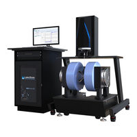
Lake Shore Cryotronics 8604 User Manual (184 pages)
VSM System
Brand:
Lake Shore Cryotronics
| Category:
Measuring Instruments
| Size: 24.53 MB
Table of Contents
Table of Contents
7
Chapter 1: Introduction
13
General
13
Product Description
13
Materials and Measurements
14
8600 Series Features
14
8600 Series VSM System Software Features
14
Integrated Scripting Tool
14
Integrated FORC Data Acquisition
15
Accessories and Options
15
Technical Specifications
16
System Standard Equipment and Specifications
16
Safety
16
Handling Liquid Helium and Liquid Nitrogen
18
Recommended First Aid for Lhe and LN 2 Exposure
18
Electrostatic Discharge
19
Identification of Electrostatic Discharge Sensitive Components
19
Handling Electrostatic Discharge Sensitive Component
19
Equipment Safety Symbols
20
Chapter 2: System Overview
21
General
21
Major Components
21
Measurement Platform
22
Electromagnet
22
Instrument Console
23
Instrumentation
23
Power Supply
23
Computer and Monitor
23
System Software
23
VSM Head Drive
24
X/Y/Z Adjustment
24
Sample Rotation
24
Pick-Up Coil Sets
24
Configurations, Options, and Accessories: Model 8604 and Model 8607
25
Model 86-CRYO Variable Temperature Cryostat
25
With Glidelock™ Alignment System
25
Model 86-OVEN High Temperature Oven
27
With Glidelock™ Alignment System
27
Model 86-SSVT Single-Stage Variable Temperature Option
28
With Glidelock™ Alignment System
28
Model 86-VTA Temperature Option Kit
28
Model 705 Gas Controller
28
Quicklign™ Sample Rods and Holders
29
General Accessories
29
Hall Probe
29
Pumps and Chillers
29
Model TPS-FRG Turbomolecular Vacuum Pump
29
E2M Rotary Pump
29
Recirculating Chillers
29
Theory of Operation
30
Chapter 3: Installation and Setup
31
General
31
Site Requirements
31
Environmental Requirements
31
Vibration Damping
31
Leveling: Model 8604 and Model 8607
32
Required Tools
32
Leveling the Magnet Platform
32
Aligning the Isolation Frame
33
Placing the VSM Head on the Isolation Frame
34
Initial Adjustment of the Tip/Tilt of the Z Translation Stage
36
Checking the Rotation Stage
38
Initial Adjustment of the Tip/Tilt of the VSM Head
40
Final Adjustment of the Tip/Tilt of the Z Translation Stage
41
Final Adjustment of the Tip/Tilt of the VSM Head
42
Final Check
43
Power Requirements
44
Power Requirements for Systems with CE Certification
44
Water Requirements
45
Cryogen Requirements
45
Vacuum Requirements
45
Gas Requirements
46
Making Connections
47
Cooling Water Connections
47
Electromagnet Cooling Water
47
Flow Switch
48
Power Supply Cooling Water
49
Instrument Console Connections
50
Model 737 VSM Controller Connections
50
Model 336 Temperature Controller Connections
51
Model 142 Amplifier Connections
52
Model 705 Gas Controller Connections
53
Computer Connections
54
Magnet/Vsm Drive Electrical Connections
55
Electromagnet Connections
55
10-Inch Electromagnet Connections
56
VSM Head Drive Connections
57
VSM Pick-Up Coils and Connections
58
Coil Wiring
58
Coil Mounting
58
Head Leveling/Alignment
60
Gaussmeter Probe Holder Installation
61
Changing Probes
62
Probe Handling
62
Probe Accuracy Considerations
62
Magnet Power Supply Connections
63
Model 643 Electrical Connections
63
Model 648 Electrical Connections
64
Installing the Options: Model 8604 and Model 8607
65
Temperature Option Installation: for All Temperature Options
65
Installing the Temperature Options
65
Model 86-SSVT Single-Stage Variable Temperature Option
67
Additional Setup
67
Making Connections
67
Applying the Vacuum
67
Verifying the Noise-Free System
67
Applying the Gases
67
Model 86-CRYO Variable Temperature Cryostat Option
68
Additional Setup
68
Making Connections
68
Applying the Vacuum
68
Verifying the Noise-Free System
68
Model 86-OVEN High Temperature Oven Option
69
Additional Setup
69
Making Connections
69
Applying the Vacuum
69
Verifying the Noise-Free System
69
Flow Meter Assembly
70
Model 86-VEC Vector Coils Option Setup
71
General
73
Preparing the System for Operation
73
System Startup
73
System Shutdown
73
Operating the Standard System Hardware
74
Operating at Room Temperature
74
Moving into the Measurement Position
74
Electrical Connections
75
Avoiding Water Condensation
76
Mounting a Sample
77
Quicklign™ Sample Rods and Holders
77
Room Temperature and Cryogenic Application
77
Sample Rods and Holders
77
High Temperature Application Sample Rods and Holders
79
Single Piece Integrated Sample Rods and Holders
80
Bulk/Powder Sample Holders
80
Liquid Sample Holders
80
Gel Sample Holders
80
Thin-Film Sample Holders
81
Installing a Sample Rod (Room Temperature)
81
Installing a Sample Rod (Variable Temperature)
83
Sample Saddling
84
Sample Rod Rotation Adjustment
85
Operating the Magnet Hardware
87
Changing the Magnet Index Setting: Model 8604 and Model 8607
87
Changing the Magnet Index Setting
87
Index Setting
89
Exchanging the Pole Caps
89
Removing the Pole Caps
89
Installing the Pole Caps
90
Preparing the System for Use after Changing the Pole Caps
90
Basic Operation of the Options: Model 8604 and Model 8607
91
Model 86-SSVT Single-Stage Variable Temperature Option
91
Warm up Sample Space and Condenser
92
SSVT Temperature Control Domains
92
Temperature Option
93
Cool down
94
Temperature Option
94
Operational Techniques
94
Model 86-CRYO Variable Temperature Cryostat Option
96
Cryostat Temperature Control Domains
96
Operating the Model 86-CRYO Cryostat Option
97
Preparing for Cool down
97
Cool down
98
Shutting down the Model 86-CRYO Cryostat Option
98
Operational Techniques
98
Model 86-OVEN High Temperature Oven Option
100
Model 86-OVEN Operation Overview
101
Other Oven Information
102
Model 86-VEC Vector Coils Option
104
Calibration
104
General
105
Maintenance
105
Preventive Maintenance Schedule
105
Cleaning the Sample Holders
106
Kel-F® Sample Holders
106
Boron Nitride Sample Holders
106
Instrument Maintenance
106
Electromagnet Maintenance
106
Cleaning the Electromagnet Surfaces
106
Condensation
106
Foreign Matter
106
Storage
106
Electromagnet Power Supply Maintenance
107
Measurement Platform Maintenance
107
Cleaning the Measurement Platform Surfaces
107
Cleaning the Sliding Plate Track
107
Cleaning the Water Filter
107
Chiller Maintenance
107
Model 86-VEC Vector Coils Option Maintenance
107
Calibration
107
Troubleshooting Procedures
108
Field Troubleshooting
108
Water Flow Interruption Recovery
108
Magnet Power Supply Interlock Troubleshooting
108
Vacuum Troubleshooting
110
Testing the Turbo Vacuum Pump Alone
110
Connections to the Options
110
General Troubleshooting
111
Avoiding Cooling Water Condensation
111
Verifying the Water Flow
111
Troubleshooting the Options
112
Cryostat Option Troubleshooting
112
Model 86-Oven/Model 8610-OVEN Option Troubleshooting
112
Option Troubleshooting
113
Service Reference
114
Line Voltage Selection
114
Electrical Ground Connection
114
Electrostatic Discharge
115
Identification of Electrostatic Discharge Sensitive Components
115
Handling of Electrostatic Discharge Sensitive Components
115
Fuse Replacement
115
Wiring Tables
116
Wiring Tables for the 8600 Series Base System
116
Wiring Tables for the 8600 Series Variable Temperature Options
120
Wiring Diagrams
122
Technical Inquiries
126
Contacting Lake Shore
126
Return of Equipment
126
Additional Magnet Shipping Instructions
126
RMA Valid Period
126
Shipping Charges
127
Restocking Fee
127
Appendix A: Glossary of Terminology
129
General
129
Appendix B: Site Preparation
139
Site Requirements
139
Unpacking and Inspecting
139
Inspecting for Shipping Damage
139
Required Tools
139
Unpacking the System
140
Unpacking the Options: Model 8604 and Model 8607
141
Single-Stage Variable Temperature Option
141
Variable Temperature Cryostat Option
141
High Temperature Oven Option
141
Unpacking the Options: Model 8610
142
Variable Temperature Cryostat Option
142
High Temperature Oven Option
142
Shipping Containers
142
Space Requirements and Suggested Layout
144
Location
145
Structural Integrity
146
Console Preparation
146
Electromagnet Site Preparation
146
Power Supply Site Preparation
147
Site Preparation for the Options: Model 8604 and Model 8607
148
Model 86-SSVT Single-Stage Variable Temperature Option
148
Model 86-CRYO Variable Temperature Cryostat Option
149
Model 86-OVEN High Temperature Oven Option
149
Site Preparation for the Options: Model 8610
150
Model 8610-CRYO Variable Temperature Cryostat Option
150
Model 8610-OVEN High Temperature Oven Option
151
Model X-MR Magnetoresistance (MR) Probe Option
151
Overview
153
System Overview
153
Installing the 250 MM (10 In) Electromagnet
153
Options and Accessories: Model 8610
154
Model 8610-CRYO Variable Temperature Cryostat
154
Model 8610-OVEN High Temperature Oven
156
Model X-MR Magnetoresistance (MR) Probe Option
157
Model 8610-VTA Temperature Option Kit
158
Model E2M 2-Stage Rotary Vacuum Pump Option
158
Model TPS-FRG Turbomolecular Vacuum Pump Station Option
158
Recirculating Chillers Option
158
Leveling
159
Required Tools
159
Leveling the Magnet Platform: Model 8610
159
VSM Head Mounting and Alignment
160
Placing the VSM Head on the Isolation Frame
160
Initial Adjustment of the Tip/Tilt of the Z Translation Stage
161
And Fork Flange to the Magnet/Frame
162
Checking the Rotation Stage
163
Initial Adjustment of the Tip/Tilt of the VSM Head
165
Initial Temperature Option Alignment
165
Installing the Options: Model 8610
166
Temperature Option Alignment and Installation: Model 8610-CRYO Cryostat, Model 8610-OVEN
166
Preparing the VSM Head Drive
166
Installing the Temperature Option Bracket
166
Installing the Temperature Option
169
Model 8610-CRYO Variable Temperature Cryostat Option
170
Additional Setup
170
Making Connections
170
Applying the Vacuum
171
Verifying the Noise-Free System
171
Preparing for Cool down
171
Cool down
171
Model 8610-OVEN High Temperature Option: Additional Setup
172
Making Connections
172
Applying the Vacuum
173
Verifying the Noise-Free System
173
Operation
175
Changing the Magnet Gap
175
Resetting the Center of the EM 10 Magnet Air Gap
176
Basic Operation of the Options: Model 8610
177
Model 8610-CRYO Variable Temperature Cryostat Option
177
Model 8610-OVEN High Temperature Oven Option
180
Advertisement
Advertisement
Related Products
Lake Shore Cryotronics 8600 Series
Lake Shore Cryotronics 8607
Lake Shore Cryotronics 8610
Lake Shore Cryotronics 240
Lake Shore Cryotronics 455
Lake Shore Cryotronics F41
Lake Shore Cryotronics F71
Lake Shore Cryotronics Measure Ready M81
Lake Shore Cryotronics Measure Ready M81-SSM
Lake Shore Cryotronics Categories
Measuring Instruments
Power Supply
Temperature Controller
Thermometer
Adapter
More Lake Shore Cryotronics Manuals
Login
Sign In
OR
Sign in with Facebook
Sign in with Google
Upload manual
Upload from disk
Upload from URL