Table of Contents
Advertisement
User's Manual
Teslameter
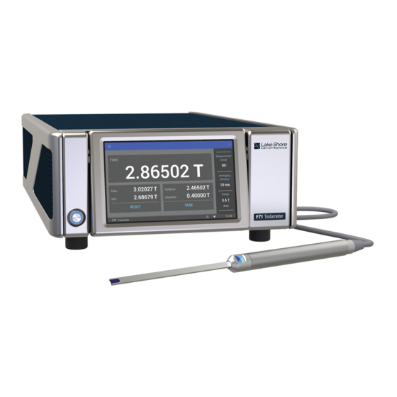
F71 Multi-axis teslameter
F41 Single-axis teslameter
Software Version 1.4
Lake Shore Cryotronics, Inc.
575 McCorkle Blvd.
Westerville, Ohio
43082-8888 USA
sales@lakeshore.com
support@lakeshore.com
www.lakeshore.com
Fax: (614) 891-1392
Telephone: (614) 891-2243
Methods and apparatus disclosed and described herein have been developed solely on company funds of Lake Shore
Cryotronics, Inc. No government or other contractual support or relationship whatsoever has existed which in any
way affects or mitigates proprietary rights of Lake Shore Cryotronics, Inc. in these developments. Methods and
apparatus disclosed herein may be subject to U.S. Patents existing or applied for.
Lake Shore Cryotronics, Inc. reserves the right to add, improve, modify, or withdraw functions, design modifications,
or products at any time without notice. Lake Shore shall not be liable for errors contained herein or for incidental or
consequential damages in connection with furnishing, performance, or use of this material.
Rev. 1.4
1 July 2019
|
www.lakeshore.com
Advertisement
Table of Contents

Related Manuals for Lake Shore Cryotronics F71


Summary of Contents for Lake Shore Cryotronics F71
- Page 1 Cryotronics, Inc. No government or other contractual support or relationship whatsoever has existed which in any way affects or mitigates proprietary rights of Lake Shore Cryotronics, Inc. in these developments. Methods and apparatus disclosed herein may be subject to U.S. Patents existing or applied for.
- Page 2 Specifically, except as provided herein, 13.Except to the extent allowed by applicable law, the terms of this limited warranty statement do not exclude, restrict or modify the mandatory statutory rights applicable to the sale of the product to you. F71/F41 Teslameter...
- Page 3 Copyright 2018–2019 Lake Shore Cryotronics, Inc. All rights reserved. No portion of this manual may be reproduced stored in a retrieval system, or transmitted, in any form or by any means, electronic, mechanical, photocopying, recording, or otherwise, without the express written permission of Lake Shore.
- Page 4 Westerville, OH 43082 Object of the declaration: Model(s): F41, F71 Description: Single-axis (F41) and Multi-axis (F71) Teslameter The object of the declaration described above is in conformity with the relevant Union harmonization legislation: 2014/53/EU Radio Equipment Directive References to the relevant harmonized standards used to the specification in relation to which conformity is...
- Page 5 Electromagnetic Compatibility (EMC) for the F71/F41 Teslameter Electromagnetic Compatibility (EMC) of electronic equipment is a growing concern worldwide. Emissions of and immunity to electromagnetic interference is now part of the design and manufacture of most electronics. To qualify for the CE Mark, the teslameter meets or exceeds the requirements of the European Radio Equipment Directive 2014/53/EU.
- Page 6 FCC and IC Compatibility for the F71/F41 Teslameter The radio transmitter/receiver in the teslameter adheres to Federal Communications Commission (FCC) and Indus- try Canada (IC) requirements. The teslameter contains the following certification numbers: FCC ID: TFB-TIWI-01 IC: 5969A-TIWI101 This device is granted for use in mobile-only configurations in which the antennas used for this transmitter must be installed to provide a separation distance of at least 20 cm from all persons, and not be co-located with any other transmitters except in accordance with FCC and Industry Canada multi-transmitter product procedures.
-
Page 7: Table Of Contents
Table of Contents Chapter 1: 1.1 Overview ................1 1.2 Features . - Page 8 6.9.5 Restocking Fee ..............89 F41/F71 Teslameter...
-
Page 9: Chapter 1: Introduction
1.1 Overview Perfect for measuring magnetic fields in a wide variety of applications, Lake Shore’s F71 and F41 teslameters with FP Series probes offer a new level of precision, conve- nience, and dependability. Some applications include: Scientific and materials research... -
Page 10: Connectivity And Usability-Communication Options
Ethernet: allows full control and reporting throughout an IP network WLAN/Wi-Fi: provides wireless access for web applications FIGURE 1-1 Communications connections 1.4 Hall Probe Full details on FP Series probes are provided on our website. Please see: https://www.lakeshore.com/products/categories/overview/magnetic-products/hall- Selection probes/fp-series-hall-probes. F71/F41 Teslameter... -
Page 11: Specifications
1.5 Specifications Full specifications about the F71/F41 teslameter are provided on our website. Please see: https://www.lakeshore.com/products/categories/specification/magnetic- products/gaussmeters-teslameters/f71-and-f41-teslameters. Feature Description Power requirement 100 V to 240 V (universal input), 50 Hz to 60 Hz, 30 VA 216 mm wide × 87 mm high × 369 mm deep Size (8.5 in ×... -
Page 12: Safety Summary And Symbols
Symbols intended instrument use. Lake Shore Cryotronics, Inc. assumes no liability for user failure to comply with these requirements. The F71/F41 teslameter protects the operator and surrounding area from electric shock or burn, mechanical hazards, excessive temperature, and spread of fire from the instrument. - Page 13 Improper Use If the instrument is used in a manner that is not specified by Lake Shore, the safety protections provided by the instrument are no longer guaranteed, and may be impaired. Equipment protected throughout Direct current (power line) by double insulation or reinforces insulation (equivalent to Class II of Alternating current (power line) IEC 536—see Annex H)
- Page 14 1: Introduction HAPTER F71/F41 Teslameter...
-
Page 15: Chapter 2: Installation
Instruments themselves may be shipped as several parts. The items included with the F71/F41 teslameter are listed below. Contact Lake Shore immedi- ately if there is a shortage of parts or accessories. Lake Shore is not responsible for any missing items if not notified within 60 days of shipment. -
Page 16: Front Panel
2: Installation HAPTER 2.3 Front Panel The F71/F41 teslameter has a 5 in capacitive touch, color TFT display with LED back- light, which is used to control the instrument and display relevant output settings and the instrument state. FIGURE 2-1 F71/F41 teslameter front panel... -
Page 17: Rear Panel
2.4 Rear Panel This section provides a description of the F71/F41 teslameter rear panel connections. FIGURE 2-3 F71/F41 teslameter rear panel Connector Description Option card slot Field control option Line input assembly Power is provided through the line input assembly. -
Page 18: Field Control Module
2: Installation HAPTER 2.4.1 Field Control The F71/F41 teslameter can be fitted with a field control option card that provides a high precision control voltage output for electromagnet systems. The stable and Module accurate probe field measurement completes the closed-loop control configuration. -
Page 19: Digital I/O Port
2.4.3 Digital I/O Port See section 3.5.5 for features of the digital I/O port. FIGURE 2-6 Digital I/O port 2.4.4 Probe Input This section describes the probe input connection and pin-out details. Connector The Lake Shore Hall probe plugs into the 26-pin mini D-sub socket on the rear panel. Align the probe connector with the probe input socket and push straight in. -
Page 20: Analog Output
HAPTER 2.4.5 Analog Output The F71/F41 teslameter has an analog output that can provide a DC voltage propor- tional to the corrected field measurement or the amplified raw Hall voltage. This set- ting can be configured through the front panel or through the remote interfaces. -
Page 21: Chapter 3: Operation
Chapter 3: Operation 3.1 General This chapter provides instructions for the operating features of the F71/F41 teslameter. 3.2 Instrument Refer to the table below for details on the power button operation. Power Power button Power mode Enter mode by: Return to ON by:... -
Page 22: Basic Operation
3: Operation HAPTER 3.4 Basic The Home screen displays readings such as magnitude, max hold, relative, XYZ (F71), and frequency. Touch a box on the screen to navigate to a detail screen containing Operation more information. The following quick access settings are also available on the Home screen:... - Page 23 Crest factor (peak/RMS) ÷ Peak to peak DC offset Time FIGURE 3-3 Available field measurements in AC mode The DC level is the rolling average field measured over the averaging window period (see section 3.4.2). The instrument subtracts this DC level from the RMS measure- ment, meaning the RMS measurement only includes the AC component of the field.
-
Page 24: Averaging Window
10 ms measurement regardless of the window. For example, a 10 s averaging window could be queried once every second and each returned value would be an average of the previous 10 s. F71/F41 Teslameter... -
Page 25: Autorange And Range Selection
This allows time for the rolling average to stabilize after being reset. 3.4.3 Autorange and The F71/F41 teslameter is equipped with an autoranging feature that will automati- cally select the appropriate range for the measured field. In some cases it may be Range Selection desirable to manually select the field range. -
Page 26: Field
Frequency is calculated by counting DC value crossings. This value is most accurate when measuring a fairly consistent AC signal with a strong fundamental frequency (AC modes only) and amplitude greater than 1% of range. FIGURE 3-8 Frequency detail F71/F41 Teslameter... -
Page 27: Max Hold Function
3.4.6 Max Hold The Max Hold function records maximum and minimum values, with the ability to reset these values to the present reading at any time. Accessing the detail screen will Function allow you to reset values individually. FIGURE 3-9 Max Hold detail in AC mode 3.4.7 Relative The Relative measurement allows you to take field measurements relative to a base- line field. -
Page 28: Temperature Measurement
2. Tap Lock. A message indicating that the screen is locked appears in the status bar. To unlock the screen: 1. Tap the lock icon in the upper right corner of the screen. 2. Tap UNLOCK in the status bar. The screen unlocks. F71/F41 Teslameter... -
Page 29: Advanced Operation
3.5 Advanced The following sections explain the more advanced features of the F71/F41 teslameter. To find these settings, tap the Settings menu (top left corner of Operation the screen) to access the navigation drawer, then select an option. FIGURE 3-12 Navigation drawer 3.5.1 Sensor... -
Page 30: Field Control (Optional)
3.5.2.1.1 Voltage Limit The full span of the field control option card is ±10V. However some magnet power supplies are not designed to operate at those voltages, so a limit can be set on the out- put voltage. F71/F41 Teslameter... - Page 31 3.5.2.1.2 Maximum Slew Rate Limit The slew rate is the rate of change in the output voltage of the field control option card. This rate can be limited to protect the magnet power supply. The Slew rate limit will be used even when a step change is requested (including when disabling field control while actively controlling).
- Page 32 An even lower setting of one quar- ter may be desired for minimal overshoot. See FIGURE 3-17(b). 3.5.2.3.3 Integral The integral term, also called reset, looks at error over time to build the integral con- tribution to the output. F71/F41 Teslameter...
- Page 33 By adding the integral to proportional contributions, the error history will push the output towards a stable value. When the error is at zero, controlling at the setpoint, the output is held constant by the integral contribution. The integral setting (I) is more predictable than the proportional setting.
- Page 34 Swipe up on the screen to reveal the Advanced Settings button, which returns to the Field control Overview screen. FIGURE 3-18 Field control A voltage limit warning will display on the detail screen and on the Home screen when the voltage control limit is reached. FIGURE 3-19 Field control F71/F41 Teslameter...
-
Page 35: Buffered Data Streaming
1.28 seconds, therefor it should be queried about every half sec- ond. For more information about buffer best practices, applications, and example code please see the Fast Magnetic Field Mapping with F71/F41 Teslameters white paper (https://www.lakeshore.com/docs/default-source/product-downloads/fast- magnetic-field-mapping-with-f-series-teslameters.pdf?sfvrsn=6284a805_6). - Page 36 The approximate relationships in the table are only valid over the flat frequency response bands of both the teslameter and probe. Higher frequencies will appear to have increased gain factors due to higher probe voltages as a result of inductive pickup in the probe. F71/F41 Teslameter...
-
Page 37: Digital I/O
3.5.5 Digital I/O The F71/F41 teslameter comes equipped with digital I/O for general purpose input/ output (GPIO) use, allowing for integration of hardware control and monitoring. There are two isolated differential inputs, two isolated solid state relay outputs, an isolated +5 V supply, and an isolated ground. - Page 38 The state of the input pins can be read using the DIGital:IDATa? query. The returned integer is a bitwise representation of the logic level presented at the respec- tive inputs (i.e., bit 0 = state of input 1, bit 1 = state of input 2). F71/F41 Teslameter...
- Page 39 Interface Commands: DIGital:INPut#:FUNCtion, DIGital:IDATa? +35 V HIGH (1) HIGH (1) +4 V +1 V LOW (0) LOW (0) -5 V – – INPUT 2 INPUT 1 FIGURE 3-23 Input diagram The input states are sampled every 10 ms in sync with the field reading minimum averaging window.
-
Page 40: Temperature Compensation
Hall probe sensor is oper- ating. The manual compensation temperature can be set via the front panel or through serial commands, for example: SENSe:TCOMpensation:MTEMperature FIGURE 3-26 Manual temperature compensation F71/F41 Teslameter... -
Page 41: Cryogenic Operation
As the fre- Frequency Operation quency of the field increases so does the inductive voltage. The F71/F41 teslameter compensates for the inducted voltages by default using a digital low-pass filter. This feature is enabled by default whenever a probe is connected. -
Page 42: System Settings
The date and time the teslameter was last calibrated successfully at Lake Shore. The ambient temperature experienced by the teslameter at the time of calibra- Calibration temperature tion. This temperature is relevant when considering the 1 year DC accuracy speci- fications for the teslameter. TABLE 3-3 About fields F71/F41 Teslameter... - Page 43 3.5.9.2 Connectivity The following fields are displayed on the Connectivity tab. Touch the enable switch next to each option to change settings: FIGURE 3-30 System settings: Connectivity tab Field Description Wifi Enables Wi-Fi connectivity. Ethernet Touch the Ethernet box to see IP settings. Determines whether the teslameter will respond to SCPI commands from the Wi-Fi or Ethernet connection.
- Page 44 3.5.9.4 Legal This screen is available for the user to see the various wireless communication certifi- cations to which the F71/F41 teslameter adheres. In addition, the attribution notices for the open source software used in the teslameter are listed here.
-
Page 45: Factory Reset Menu
3.5.9.7 Date and Time The teslameter contains a real-time clock, allowing the current date, time, and time zone to be stored. The time, date and time zone can be set and viewed via the front panel or over the remote interface. In addition, the teslameter has a feature to automatically set its date and time. -
Page 46: Firmware Updates
3.5.11.1 Overview Updates The F71/F41 teslameter can update its firmware manually by attaching a USB Type-C™ stick to the rear panel. However, the easiest method is to connect the instrument to the internet via Ethernet or Wi-Fi, and update directly from the Lake Shore firmware server. - Page 47 The firmware can be downloaded from the Lake Shore website and manually installed on the teslameter using a USB Type-C™ stick: 1. Go to https://www.lakeshore.com/products/categories/downloads/magnetic- products/gaussmeters-teslameters/f71-and-f41-teslameters to download the firmware. 2. Enter your name and e-mail address so that we can keep you updated on any new firmware for your instrument.
-
Page 48: Probes
The generated Hall voltage for a given field will vary with temperature. Each standard Hall probe contains a temperature sensor at the tip, allowing the detection of sensor temperature, and applying temperature compensation around room temperature. Cryogenic probes do not measure temperature and should be compensated manu- ally. F71/F41 Teslameter... -
Page 49: Probe Types
3.6.2 Probe Types 3.6.2.1 Sensor 2Dex™ sensors are currently the only sensor types available with FP Series probes. 2Dex sensors offer a great balance of sensitivity, linearity, stability and ruggedness. These sensors set the new standard for the majority of field measurement applica- tions. - Page 50 3.6.2.4 Stem Length Stem length is defined as the distance from the end of the handle or mounting fixture to the tip of the probe. Please be aware that stem deflection can occur on longer stems when aligned horizontally. F71/F41 Teslameter...
-
Page 51: Installation
3.6.2.5 Form Factor 3.6.2.5.1 Handheld The default handle configuration is a handheld probe with an anodized aluminum grip for a solid and long-lasting grip surface. Labels at the end of the handle serve as a way to identify polarity and handle orientation. FIGURE 3-40 Handheld 3.6.2.5.2 Mountable The mountable form factor features a flat machined aluminum surface for use in situ-... - Page 52 3.6.3.2.3 Probe Orientation Mountable probes have the Lake Shore logo on just one side of the probe, making it easier to repeatedly mount the probe in the same orientation and ensure the polarity and/or sensor location is not accidentally swapped. F71/F41 Teslameter...
- Page 53 3.6.3.3 Connection All probes have the same connector and spring-loaded latching mechanism to make connections to the teslameter easier. When making a connection, the following points should be considered: The connector is not rotationally-symmetrical, please ensure that the largest side of the connector is facing upwards. FIGURE 3-43 Probe input connector The connector is fully attached when the latching mechanisms on both sides of the connector click into place.
-
Page 54: Operation
A ruler has been added to the stem indicating distance from the active area (not the tip of the stem). FIGURE 3-46 Transverse Flexible-Thin (TF) probe active area FIGURE 3-47 Transverse Flexible-Thin (TF) probe Left: cold side; Right: hot side F71/F41 Teslameter... - Page 55 3.6.4.1.3 Transverse Cryogenic (TC): Future release. 3.6.4.1.4 Axial Standard (AS) The active area of this stem is located beyond the aluminum housing a fraction of a millimeter from the tip. It is centered on the axis of the stem without any visual indi- cation of where the active area is located.
- Page 56 Y-axis: positive field reading when field passes through the probe from the side marked with Y to the side without a Y. Z-axis: positive field reading when field is directed into the probe stem. FIGURE 3-54 3-Axis polarity F71/F41 Teslameter...
-
Page 57: Chapter 4: Computer Interface Operation
Instruments (SCPI) standard, regardless of the remote interface selected for user con- trol. 4.2 Standard The F71/F41 teslameter adheres to the SCPI command language. SCPI is a standard- ized command language, presently maintained by the Interchangeable Virtual Commands for Instruments (IVI) Foundation, used for controlling test and measurement instru- Programmable ments. -
Page 58: Queries
To do this, separate each command/query with a semicolon Commands in a Single and be sure to include a colon before the next command, unless it is a common com- Message mand which uses the “*” prefix. F71/F41 Teslameter... -
Page 59: Terminators
All of this is the responsibility of the user program. Most commands sent to the F71/F41 teslameter will execute within 100 ms of the last character being transmitted. However, the SCPI command protocol does not specify that an instrument return an acknowledge message when a given command is finished executing. -
Page 60: Status And Error Reporting
4.3 Status and Error Reporting 4.3.1 Status System The F71/F41 teslameter implements a status system compliant to the SCPI-99 stan- dard. The SCPI status system is derived from the status system called out in Overview Chapter 11 of the IEEE 488.2 standard. The status system provides a method of recording and reporting instrument information. - Page 61 4.3.1.2 Service Request Enable Register The service request enable register determines which summary bits in the status byte will set the MSS bit of the status byte. The user may write to or read from the service request enable register. Each status byte summary bit is logically ANDed to the corre- sponding enable bit of the service request enable register.
-
Page 62: Register Details
Since the F71/F41 teslameter does not have a GPIB interface, this bit is strictly referred to as the MSS bit. - Page 63 4.3.2.2 Service Request Enable Register The service request enable register is programmed by the user and determines which summary bits of the status byte may set bit 6 (MSS). Enable bits are logically ANDed with the corresponding summary bits (FIGURE 4-2). Whenever a summary bit is set by an event register and its corresponding enable bit is set by the user, bit 6 will be set.
- Page 64 15 14 13 12 11 10 9 — Bit STATus:OPERation:ENABle status byte — Name NDBA RMPD RNIG OVRL NOPR used used used used used used used used used used used STATus:OPERation:ENABle? register FIGURE 4-4 Operation event status register F71/F41 Teslameter...
- Page 65 4.3.2.5 Questionable Status Register Set The questionable status register reports various states of the instrument that could indicate the quality of the output signal may be compromised. Any or all of these events may be reported in the questionable event summary bit through the enable register (FIGURE 4-5).
-
Page 66: Error Messages
A comprehensive list of standard SCPI error codes descriptions can be found in chapters 21.8.9 through 21.8.16 of the official SCPI 99 standard, located on the IVI foundation website: http://www.ivifoundation.org/docs/scpi-99.pdf. The F71/F41 teslameter does not implement every error code listed in the standard. F71/F41 Teslameter... -
Page 67: Remote Interfaces
4.4 Remote This section provides operational instructions for the three remote interfaces for the Lake Shore F71/F41 teslameter. Each of the three interfaces provided with the Interfaces teslameter source permit remote operation. 4.4.1 USB The USB interface provides a convenient way to connect to most modern computers. - Page 68 Click on the Device Manager link in the Search Results Under Programs dia- log box. c. If User Account Control is enabled click Continue on the User Account Control prompt. 5. Click View and ensure the Devices by Type check box is selected. F71/F41 Teslameter...
-
Page 69: Ethernet And Wi-Fi
4.4.2 Ethernet and The Ethernet and Wi-Fi interfaces provides a means of connecting the F71/F41 teslameter to an Ethernet or Wi-Fi based computer network. These net- Wi-Fi works provide the ability to communicate across large distances, often using existing equipment (the internet, pre-existing local networks). - Page 70 This can be done by touching Other network at the bottom of the available network list, or by tapping the action icon (three dots in the top right corner of the screen) and selecting Add network. FIGURE 4-8 Wi-Fi settings F71/F41 Teslameter...
- Page 71 At that point, the SSID, security mode and IP setting type can be entered: FIGURE 4-9 Network parameters If static IP is desired, touch IP settings then select Static. The static IP items are listed, including IP address, gateway, DNS, and network prefix length. Network prefix is an alternative way to present the subnet mask.
- Page 72 Gateway Address: a gateway is a network traffic routing device that is used to route communication between networks. If a gateway is not used, then devices on a network can only communicate with other devices on that same network. A gate- F71/F41 Teslameter...
- Page 73 4.4.2.5 TCP Socket Communication A TCP socket connection interface is provided as the communication medium for the network interface of the F71/F41 teslameter. A TCP socket connection, or simply “socket connection”, is a common connection protocol used by Ethernet devices. The...
-
Page 74: Scpi Over Tcp
IP address and socket of the teslameter. In order to issue SCPI commands over TCP and remotely control the instrument, this setting needs to be enabled. This can be done by touching the switch, as shown below. FIGURE 4-12 SCPI over TCP F71/F41 Teslameter... -
Page 75: Command Summary
4.5 Command This section provides a listing of the interface commands. Summary 4.5.1 Common The following commands and queries are specified in both IEEE 488.2 and SCPI-99. Commands *CLS Command Format *CLS Remarks Clears status data structures and forces the device in to Operation Complete Com- mand Idle State and the Operation Complete Query Idle State. - Page 76 4. Any event enable setting, including the standard event status enable register set- tings. 5. Any event register setting, including the standard event status register settings. 6. The power-on-status-clear flag setting. 7. Macros defined with the define macro contents command. F71/F41 Teslameter...
- Page 77 8. Calibration data that affects device specifications. 9. The protected user data query response. 10. The resource description transfer query response. 11. The service request enable register setting. 12. The parallel poll enable register setting. 13. The memory registers associated with *SAV. *SRE Command Format *SRE <decimal numeric program data>...
-
Page 78: Scpi Subsystem Commands
Clears the error queue. Returns the number of errors SYSTem:ERRor:COUNt? in the queue. Returns the most recent error SYSTem:ERRor[:NEXT]? in the queue and removes it. Resets all settings to their fac- SYSTem:FACTORYRESET tory defaults. This includes System settings. F71/F41 Teslameter... - Page 79 Command Parameter(s) Description Returns whether the front SYSTem:KLOCk? panel touch screen is locked. <Boolean 0 = FALSE, Locks and unlocks the front SYSTem:KLOCk 1 = TRUE> panel touch screen. Resets the measurement set- SYSTem:PRESet tings to their default values. Returns the hour, minute, and SYSTem:TIME? second in 24 hour time.
- Page 80 TSOurce | NONE> temperature measure- ment source. It can also disable compensation (NONE). SENSe:TCOMpensation: Returns the manual MTEMperature? temperature value. SENSe:TCOMpensation: <temperature in Configures the manual MTEMperature Celsius> temperature value. Returns whether cryo- SENSe:CRYO? genic operation is enabled. F71/F41 Teslameter...
- Page 81 Command Parameter(s) Description <Boolean 0 = FALSE, 1 Enables or disables SENSe:CRYO = TRUE> cryogenic operation. Returns whether probe SENSe:PCOMpensation? frequency compensa- tion is enabled. Enables or disables <Boolean 0 = FALSE, 1 SENSe:PCOMpensation probe frequency com- = TRUE> pensation. 4.5.2.6 Analog Output Command Parameter(s)
- Page 82 Tesla is the default. Returns whether a user can UNIT:CGSDISABLE? change their field measure- ment units to gauss. Configures whether a user can <Boolean 0 = FALSE, UNIT:CGSDISABLE change their field measure- 1 = TRUE> ment units to gauss. F71/F41 Teslameter...
- Page 83 4.5.2.10 Field Control Command Parameter(s) Description Returns whether field control is SOURce:FIELd:STATe? on or off. <Boolean 0 = FALSE, SOURce:FIELd:STATe Turns field control on and off. 1 = TRUE> Returns the present field con- SOURce:FIELd:MODE? trol mode. Sets field control to open loop or SOURce:FIELd:MODE <CLLoop|OPLoop>...
- Page 84 4: Computer Interface Operation HAPTER F71/F41 Teslameter...
-
Page 85: Chapter 5: Probes And Accessories
Chapter 5: Probes and Accessories 5.1 General This chapter provides information on standard probes and the accessories available for the F71/F41 teslameter. 5.2 Models The list of F71/F41 teslameter model numbers follows: Model Description F41 teslameter F71 teslameter TABLE 5-1 Model description Full details on FP Series probes are provided on our website. -
Page 86: Rack Mounting
Full rack mount tray Additional screws are included Screw, M4 × 5 mm FHM Phillips for use with other Lake Shore Washer, 1.6 to 1.8 mm THK or third-party instruments. FIGURE 5-1 Full rack mounting F71/F41 Teslameter... -
Page 87: Half Rack Mounting
5.4.2 Half Rack Refer to the figure below for half rack installation details. Mounting Item Description Rack mount panel Rack mount ear Half rack mount tray Screw, M4 × 5 mm FHM Phillips Screw, M4 × 8 mm FHM Phillips Washer, 1.6 to 1.8 mm THK If a non-XIP full rack instrument will be installed... - Page 88 5: Probes and Accessories HAPTER F71/F41 Teslameter...
-
Page 89: Chapter 6: Service
Lake Shore for service (section 6.9). 6.2 General If the F71/F41 teslameter registers a reading that is not appropriate to the situation, try the following solutions. Troubleshooting Refer to section 6.5 for a list of error messages... -
Page 90: Intermittent Lockups
6.4 Line Voltage The F71/F41 teslameter will operate between the range of 100 VAC to 240 VAC, 50 Hz or 60 Hz configurations so that it can be operated from line power anywhere in the world. -
Page 91: Rear Panel Connector Definitions
6.7 Rear Panel This section describes the rear panel connections. Connector Definitions FIGURE 6-1 Digital I/O port Description Description Ground Ground Power Power Input 2 low Relay 2 low Input 2 high Relay 2 high Input 1 low Relay 1 low Input 1 high Relay 1 high TABLE 6-2 Digital I/O pinouts... - Page 92 Power from switch- (not used) EPWR- Power from switch- (not used) TABLE 6-4 Ethernet pin and connector details FIGURE 6-4 USB pin and connector Symbol Description +5 VDC Data- Data+ Ground TABLE 6-5 USB pin and connector details F71/F41 Teslameter...
- Page 93 FIGURE 6-5 USB Type-C™ connector TX1+ TX1- VBUS CC1 SBU1 VBUS RX2- RX2+ RX1+ RX1- VBUS SBU2 VBUS TX2- TX2+ FIGURE 6-6 USB Type-C™ connector Name Description Name Description Ground return Ground return SuperSpeed differential pair #1, SuperSpeed differential pair #2, SSTXp1 SSRXp1 TX, positive...
- Page 94 Adapter-Detect EEPROM-Power Connector-Detect2 Temperature voltage - Ground Connector-Detect EEPROM-Data Ground Temperature current + TABLE 6-7 Probe input connector details FIGURE 6-8 BNC connector Description Center conductor Output high Outer shield Output low (instrumentation ground) TABLE 6-8 BNC connector F71/F41 Teslameter...
-
Page 95: Summary Of Internal Memory Devices
6.8 Summary of This section outlines the internal memory devices used inside the F71/F41 teslameter, and provides an explanation of the types of data they contain. Internal Memory Devices Printed circuit Field Manufacturer Part number Description Location Function Volatility board... -
Page 96: Technical Inquiries
You will receive a response within 24 hours or the next business day in the event of weekends or holidays. If you wish to contact Service or Sales by mail or telephone, use the following: Lake Shore Cryotronics Instrument Service Department Mailing address 575 McCorkle Blvd. -
Page 97: Rma Valid Period
6.9.3 RMA Valid Period RMAs are valid for 60 days from issuance; however, we suggest that equipment needing repair be shipped to Lake Shore within 30 days after the RMA has been issued. You will be contacted if we do not receive the equipment within 30 days after the RMA is issued.
Need help?
Do you have a question about the F71 and is the answer not in the manual?
Questions and answers