Table of Contents
Advertisement
Quick Links
TABLE OF CONTENTS
Air Handler Safety ................................................................ 1
General ............................................................................... 2
Receiving ............................................................................. 2
Installation Requirements .................................................... 2
Installation ............................................................................ 3
Ductwork .............................................................................. 3
Install Condensate Drain...................................................... 4
Metering Device ................................................................... 4
Refrigerant Line Installation ................................................. 5
Refrigerant Piping ................................................................ 5
Refrigerant Charging Instructions ........................................ 5
AIR HANDLER SAFETY
SAFETY CONSIDERATIONS
Your safety and the safety of others are very important.
We have provided many important safety messages in this manual and
on your appliance. Always read and obey all safety messages.
This is the safety alert symbol.
This symbol alerts you to potential hazards that can kill or hurt
you and others.
All safety messages will follow the safety alert symbol and signal word.
These signals words mean the following:
DANGER: You can be killed or seriously injured if you don't
immediately follow instructions.
WARNING: Indicate a potentially hazardous situation which, if not
avoided, could result in death or serious injury.
Product improvement is a continuous process at Advanced Distributor Products. Therefore, product specifications are subject to change without notice
and without obligation on our part. Please contact your ADP representative or distributor to verify details.
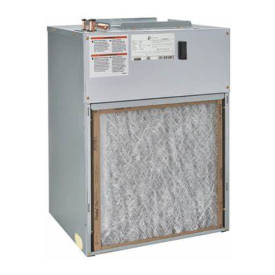
S-series
Wall Mount Air Handlers
PAGE
Filters ...................................................................................6
Electrical Requirements .......................................................6
Electrical Connections ........................................................6
Thermostat Connections ......................................................7
Electrical Data ......................................................................8
Blower Performance Data ....................................................8
Wiring Diagrams ................................................................10
Air Handler Checks ............................................................12
Air Handler Maintenance ...................................................12
Assistance or Service ........................................................12
Warranty ............................................................................13
CAUTION: Indicates a potentially hazardous situation which, if not
NOTICE: Indicates a statement of company policy as the message
IMPORTANT: More detailed information concerning the statement of
All safety messages will tell you what the potential hazard is, tell you how
to reduce the chance of injury, and tell you what can happen if the
instructions are not followed.
© by Advanced Distributor Products. All rights reserved.
2175 West Park Place Blvd., Stone Mountain, GA 30087
www.adpnow.com
Installation Instructions
avoided, may result in minor or moderate injury. Caution may also
be used to alert against unsafe practices.
relates directly or indirectly to the safety of personnel or protection of
property.
company policy as the message relates directly or indirectly to the
safety of personnel or protection of property.
IM-SAH-0654638-20
March 2024
PAGE
Advertisement
Table of Contents

Related Manuals for Adp S Series

Summary of Contents for Adp S Series
-
Page 1: Table Of Contents
Product improvement is a continuous process at Advanced Distributor Products. Therefore, product specifications are subject to change without notice and without obligation on our part. Please contact your ADP representative or distributor to verify details. © by Advanced Distributor Products. All rights reserved. -
Page 2: General
GENERAL These instructions are intended as a general guide only and do WARNING not supersede any national or local codes in any way. Compli- ance with all local, state, or national codes pertaining to this type of equipment should be determined prior to installation. Electrical Shock Read this entire instruction manual, as well as the instructions Disconnect power before servicing. -
Page 3: Installation
INSTALLATION S Series air handlers are suitable for free-air return when FIGURE 2 enclosed in a closet with a louvered door or flush mounted in a wall. *Units must always be installed with a casing. Closet or “On the Wall” Applications (Figure 2) -
Page 4: Install Condensate Drain
¾″ male pipe thread PVC fittings be used at If line makes a second trap, or has an extended run before the condensate pan. Hand tighten only! ADP recommends termination, a vent tee should be installed after the trap closest thread sealant to be used on the PVC connector at the drain pan to the pan. -
Page 5: Refrigerant Line Installation
Sharp bends or possible kinking in the lines will connected to the refrigerant lines. cause a restriction. ADP recommends installing a filter drier and sight glass in the Do not remove the caps from the lines or system liquid line. -
Page 6: Filters
FILTERS Filters are not provided with unit, and must be supplied and installed in the return air system by the installer. A field installed filter grille is recommended for easy and convenient access to the filters for periodic inspection and cleaning. Filters must have adequate face area for the rated air quantity of the unit. -
Page 7: Thermostat Connections
LOW VOLTAGE THERMOSTAT CONNECTIONS Thermostat Connections: 3-speed Motor NOTE: When the room thermostat calls for second stage heat, the first stage (heat pump) operation must be locked out. Low Voltage Thermostat Connections – 5-speed ECM Constant Torque Motor For 2 stage outdoor units: ... -
Page 8: Electrical Data
ELECTRICAL DATA 3-Speed PSC Motor Heating Capacity Minimum Circuit Am- Circuit Breaker Amps Blower Amps Unit Size pacity Per Stage BTUH (All have electric heat) 240 V 240 V 208 V 240 V 208 V 240 V 208 V 240 V 15.0 15.0 17,065... - Page 9 BLOWER PERFORMANCE DATA 3-Speed PSC Motor Airflow (CFM) vs. External Static Pressure Cooling Speed (inches W.C.) *** Unit Size Setting * ^ Low - Med - Blue High -Black 1046 1013 Low - Red * ^ Med - Blue High -Black 1046 1013 Low - Red...
-
Page 10: Wiring Diagrams
– 3- – 3- DWG. NO. 067203800 WIRING DIAGRAM - ELECTRIC HEAT PD = PULL DISCONNECT 1st STAGE HEATER SEQ1 SEQ = SEQUENCER GND = GROUND LUG 208 / 240 LS = LIMIT SWITCH 12 BK 12 BK HE = HEATER ELEMENT SUPPLY 12 BK 12 BK... - Page 11 – 5- – 5- DWG. NO. 067203900 WIRING DIAGRAM - ELECTRIC HEAT PD = PULL DISCONNECT HEATER 1st STAGE SEQ1 14 BLK SEQ = SEQUENCER GND = GROUND LUG 208 / 240 LS = LIMIT SWITCH 12 BK 12 BK HE = HEATER ELEMENT SUPPLY 12 BK...
-
Page 12: Air Handler Checks
AIR HANDLER CHECKS Check Blower Operation WARNING 1. Set thermostat to FAN ON. 2. The indoor blower should come on. Electrical Shock Hazard Check Electric Heater (if used) Disconnect all power supplies before servicing. Replace all parts and panels before operating. 1. -
Page 13: Warranty
ADP AIR HANDLER LIMITED WARRANTY Term of Warranty Equipment Information Advanced Distributor Products (ADP) warrants that products Please complete information below and retain this warranty for records and future reference. sold shall be of merchantable quality, free of defects in material...
Need help?
Do you have a question about the S Series and is the answer not in the manual?
Questions and answers