Sign In
Upload
Download
Table of Contents
Contents
Add to my manuals
Delete from my manuals
Share
URL of this page:
HTML Link:
Bookmark this page
Add
Manual will be automatically added to "My Manuals"
Print this page
×
Bookmark added
×
Added to my manuals
Manuals
Brands
H3C Manuals
Switch
S10500X-G Series
Hardware information
H3C S10500X-G Series Hardware Information
Hide thumbs
1
2
3
4
5
Table Of Contents
6
7
8
9
10
11
12
13
14
15
16
17
18
19
20
21
22
23
24
25
26
27
28
29
30
31
32
33
34
35
36
37
38
39
40
41
42
43
44
45
46
47
48
49
50
51
52
53
54
55
56
57
58
59
60
61
62
63
64
65
66
67
68
69
70
71
72
73
74
75
76
77
78
79
80
81
82
83
84
85
86
87
page
of
87
Go
/
87
Contents
Table of Contents
Bookmarks
Table of Contents
Table of Contents
Chassis
Chassis Information
Chassis Views
Slot Arrangement
Chassis Specifications
Weights and Dimensions
Total Power Consumption
Heat Dissipation
Cooling
Availability and Reliability
Environmental Specifications
Noise
Rack
Slide Rails
Modules
Naming Conventions
MPU Naming Conventions
Service Module Naming Conventions
Switch Fabric Module Naming Conventions
Mpus
Lsem1Supa0/Lsem3Supa0
Lsem1Supb0/Lsem3Supb0
400G Interface Modules
Lsem1Cdq2Sf0/Lsem3Cdq2Sf0
100G Interface Modules
Lsem1Cgq16Sf0/Lsem3Cgq16Sf0
Lsem1Cgq36Sf0/Lsem3Cgq36Sf0
40G Interface Modules
Lsem1Qgs16Sf0/Lsem3Qgs16Sf0
Lsem1Qgs36Sf0/Lsem3Qgs36Sf0
25G Interface Modules
Lsem1Ygs48Cqsf0/Lsem3Ygs48Cqsf0
10G Interface Modules
Lsem1Tgs16Gp32Sd0
Lsem1Tgs24Sd0
Lsem1Tgs48Qssf0/Lsem3Tgs48Qssf0
Lsem1Tgs48Sd0/Lsem2Tgs48Sd0
Lsem1Tgt48Sd0
1G Interface Modules
Lsem1Gt24Gp16Tssd0
Lsem1Gt48Ts24Qssd0
Lsem1Gt48Tssd0
Lsem1Gv48Tssd0
Switch Fabric Modules
Lsem1Sf06B0/Lsem1Sf06D0
Lsem1Sf08C0
Lsem1Sf12B0
Power Supplies
Psr1600B-12A-B
View
Technical Specifications
Leds
Psr1600-54A-B
View
Technical Specifications
Leds
Psr2000-12D-B
View
Technical Specifications
Leds
Fan Trays
Fan-80B-4-A
View
Technical Specifications
Leds
Fan-80B-5-A
View
Technical Specifications
Leds
Fan-80B-8-A
View
Technical Specifications
Leds
Cables
Console Cable
DC Power Cord
AC Power Cord
Ethernet Twisted Pair Cable
RJ-45 Connector
Cable Pinouts
Cable Type
Pin Assignments
Making an Ethernet Twisted Pair Cable
Optical Fiber
Optical Fiber Cable
Patch Cord
Pigtail Cord
Fiber Connector
Precautions
SFP+ DAC Cable
SFP28 DAC Cable
SFP28 AOC Cable
QSFP+ DAC Cable
QSFP+ AOC Cable
QSFP28 DAC Cable
QSFP28 AOC Cable
QSFP+ to SFP+ DAC Cable
QSFP28 to SFP28 DAC Cable
QSFP-DD Copper Cable
Advertisement
Quick Links
Download this manual
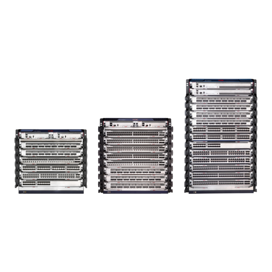
H3C S10500X-G Switch Series
Hardware Information and Specifications
New H3C Technologies Co., Ltd.
http://www.h3c.com
Document version: 6W101-20240123
Table of
Contents
Previous
Page
Next
Page
1
2
3
4
5
Advertisement
Table of Contents
Need help?
Do you have a question about the S10500X-G Series and is the answer not in the manual?
Ask a question
Questions and answers
Related Manuals for H3C S10500X-G Series
Switch H3C S10504 Installation Manual
(115 pages)
Switch H3C S10506 Installation, Quick Start
(18 pages)
Switch H3C S10504 Installation Manual
H3c s10500 switch series installation guide (104 pages)
Switch H3C S10500 Series Configuration Manual
(26 pages)
Switch H3C S10500 Series Interface Configuration Manual
(35 pages)
Switch H3C S10500 Series Configuration Manual
(50 pages)
Switch H3C S10500 Series Command Reference Manual
(16 pages)
Switch H3C S10500 Series Configuration Manual
(15 pages)
Switch H3C S10500 Series Configuration Manual
(33 pages)
Switch H3C S10500 Series Configuration Manual
(18 pages)
Switch H3C S10500X Series Installation, Quick Start
(3 pages)
Switch H3C S10500X Series Configuration Manual
(39 pages)
Switch H3C S10500X Series Configuration Manual
(13 pages)
Switch H3C S10500X Series Installation Manual
(95 pages)
Switch H3C S10506X-G Hardware Information
(87 pages)
Switch H3C S10508X-G Hardware Information
(87 pages)
This manual is also suitable for:
S10506x-g
S10506x-g-poe
S10508x-g
S10512x-g
Table of Contents
Print
Rename the bookmark
Delete bookmark?
Delete from my manuals?
Login
Sign In
OR
Sign in with Facebook
Sign in with Google
Upload manual
Upload from disk
Upload from URL


Need help?
Do you have a question about the S10500X-G Series and is the answer not in the manual?
Questions and answers