Table of Contents
Advertisement
Quick Links
Advertisement
Table of Contents

Related Manuals for Zmotion ZMC408SCAN-V22


Summary of Contents for Zmotion ZMC408SCAN-V22
- Page 2 This manual is copyrighted by Shenzhen Technology Co., Ltd., without the written permission of the Zmotion Technology, no person shall reproduce, translate and copy any content in this manual. The above-mentioned actions will constitute an infringement of the copyright of the company's manual, and Zmotion will investigate legal responsibility according to law.
- Page 3 ⚫ Zmotion will not take any legal responsibility for personal safety accidents and property losses caused by failure to comply with the contents of this manual or illegal operation of products. Safety Level Definition According to the level, it can be divided into "...
- Page 4 ◆ Improper installation of the controller may result in misoperation, failure and fire. Wiring ◆ The specifications and installation methods of the external wiring of the equipment shall comply with the requirements of local power distribution regulations. ◆ When wiring, all external power supplies used by the system should be disconnected before operation.
-
Page 5: Table Of Contents
ZMC408SCAN-V22 Bus SCAN Motion Controller User Manual V1.0 Content Chapter I Production Information..................3 1.1. System Connection ................... 3 1.2. Programming ..................... 4 1.3. Function Features ....................4 1.4. Model Introduction .................... 5 1.5. Hardware Installment ..................6 Chapter II Product Specification ..................7 2.1. - Page 6 ZMC408SCAN-V22 Bus SCAN Motion Controller User Manual V1.0 3.6.3. Wiring Reference .................. 28 3.6.4. Basic Usage Method ................30 3.7. MPG Handwheel Interface ................31 3.7.1. Interface Definition ................31 3.7.2. MPG Handwheel Interface Specification ..........32 3.7.3. Wiring Reference .................. 33 3.7.4.
-
Page 7: Chapter I Production Information
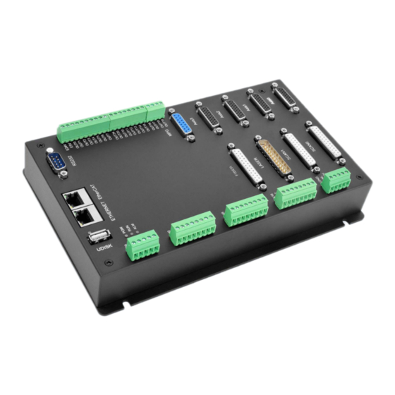
Chapter I Production Information ZMC408SCAN-V22 is a kind of high-performance fieldbus dual-SCAN motion controller launched by Zmotion. It integrates 2 100M ethernet ports, and it supports EtherCAT, EtherNET, CAN, RS232, RS485, 24 general digital inputs, 20 general digital outputs, 2 general analog inputs, 2 general analog outputs, 4 local differential pulse axes, 1 MPG handwheel encoder interface, 2 SCAN interfaces with feedback, 1 LASER interface (specialized for laser), and 1 FIBER laser interface. -
Page 8: Programming
ZMC408SCAN-V22 Bus SCAN Motion Controller User Manual V1.0 ZMC408SCAN-V22 supports EtherNET, EtherCAT, USB, CAN, RS485, and RS232 communication interfaces. And it can connect to expansion modules to extend digital IO, analog IO, or motion axis by CAN or EtherCAT. 1.2. Programming... -
Page 9: Model Introduction
ZMC408SCAN-V22 Bus SCAN Motion Controller User Manual V1.0 1 USB interface is used for storage. ◆ ◆ 1 RS485, 1 RS232, 1 CAN and 1 100M ETHERNET interface support multi-expansion applications. ◆ 2 12-bit voltage type analog outputs, output measuring range is 0-10V. 2 12-bit voltage type analog inputs, input measuring range is 0-10V. -
Page 10: Hardware Installment
ZMC408SCAN-V22 Bus SCAN Motion Controller User Manual V1.0 1.5. Hardware Installment The ZMC408SCAN motion controller is installed horizontally with screws, and each controller should be fastened with 4 screws. → Unit: mm → Mounting Hole Diameter 4.5mm... -
Page 11: Chapter Ii Product Specification
ZMC408SCAN-V22 Bus SCAN Motion Controller User Manual V1.0 Chapter II Product Specification 2.1. Basic Specification Item Description Model ZMC408SCAN-V22 Axes 8 (4 pulse axes + 4 SCAN axes) Max Extended Axes 16 (the number of axes relates to system period and... -
Page 12: Usage Environment
ZMC408SCAN-V22 Bus SCAN Motion Controller User Manual V1.0 2.2. Usage Environment Item Parameters Work Temperature 0 – 60° C (32° F - 140° F) Work Relative Humidity 5%-95% non-condensing 2.3. Interface Definition → Interface Description Mark Interface Number Description RS232... - Page 13 ZMC408SCAN-V22 Bus SCAN Motion Controller User Manual V1.0 RS485 RS485 serial port (port1) Use MODBUS_RTU protocol EtherCAT bus interface, connect to EtherCAT EtherCAT EtherCAT bus interface bus drive and EtherCAT bus expansion modules Use MODBUS_TCP protocol, expand the number of network ports through the...
-
Page 14: Chapter Iii Wiring & Communication Configuration
ZMC408SCAN-V22 Bus SCAN Motion Controller User Manual V1.0 Chapter III Wiring & Communication Configuration 3.1. Power Input The power supply input adopts a 5Pin (there are all 3 terminals) screw-type pluggable wiring terminal, and the interval (means the gap distance between two ports) should be 3.81mm. -
Page 15: Can Communication Specification & Wiring
ZMC408SCAN-V22 Bus SCAN Motion Controller User Manual V1.0 Overcurrent Protection 3.1.2. CAN Communication Specification & Wiring The CAN interface of the controller adopts the standard CAN communication protocol, which mainly includes three ports, CANL, CANH and the public end. And it can connect CAN expansion modules and other standard CAN devices. -
Page 16: Basic Usage Method
ZMC408SCAN-V22 Bus SCAN Motion Controller User Manual V1.0 → Wiring Notes: ⚫ As above, the daisy chain topology is used for wiring (the star topology structure cannot be used). When the use environment is ideal and there are no many nodes, the branch structure also can be used. -
Page 17: Rs232/Rs485 Serial Port
ZMC408SCAN-V22 Bus SCAN Motion Controller User Manual V1.0 (4) Correctly set the "address" and "speed" of the slave station expansion module according to the manual of the slave station. (5) After all the settings are completed, restart the power supply of all stations to establish communication. -
Page 18: Communication Specification
ZMC408SCAN-V22 Bus SCAN Motion Controller User Manual V1.0 Output Positive pole output of 5V power, Output maximum is 300mA 3.2.2. Communication Specification Item RS232 (port0) RS485 (port1) Maximum 115200bps 115200bps Communication Rate Terminal Resistor Connect correspondingly Topology Structure Daisy chain structure... -
Page 19: Basic Usage Method
ZMC408SCAN-V22 Bus SCAN Motion Controller User Manual V1.0 → Wiring Notes: ⚫ The wiring of RS232 (port0) is as above, it needs to cross-wiring for sending and receiving signals, and it is recommended to use a double-female head cross line when connecting to a computer. -
Page 20: In Digital Inputs
ZMC408SCAN-V22 Bus SCAN Motion Controller User Manual V1.0 (6) Communication data of RS232 / RS485 can be directly viewed through “ZDevelop / Controller / State the Controller / CommunicationInfo”. 3.3. IN Digital Inputs The digital input adopts 3 groups of 8Pin (there are 3 groups of 8 terminals) screw- type pluggable terminals, and the gap distance between terminals should be 3.81mm. -
Page 21: Digital Input Specification & Wiring
ZMC408SCAN-V22 Bus SCAN Motion Controller User Manual V1.0 low-speed input Input 9 IN10 Input 10 IN11 Input 11 IN12 Input 12 IN13 Input 13 IN14 Input 14 IN15 Input 15 IN16 Input 16 IN17 Input 17 IN18 Input 18 IN19... -
Page 22: Wiring Reference
ZMC408SCAN-V22 Bus SCAN Motion Controller User Manual V1.0 3.3.3. Wiring Reference ⚫ The wiring principle of high-speed digital input IN (0-3) and low-speed digital input IN (4-23) is shown in the figure above. The external signal source can be an optocoupler, a key switch or a sensor, etc., all can be connected as long as the... -
Page 23: Out Digital Outputs
ZMC408SCAN-V22 Bus SCAN Motion Controller User Manual V1.0 ETHERNET, RS232 and RS485 to connect to ZDevelop. (3) State values of relative input ports can be read directly through “IN” command, also, it can be read through “ZDevelop/View/In”. Please refer to “ZBasic” for details. - Page 24 ZMC408SCAN-V22 Bus SCAN Motion Controller User Manual V1.0 high- High-speed OUT1 Output 1 PWM 1 speed Comparison Out 1 output High-speed OUT2 Output 2 PWM 2 Comparison Out 2 High-speed OUT3 Output 3 PWM 3 Comparison Out 3 OUT4 Leakage...
-
Page 25: Digital Output Specification
ZMC408SCAN-V22 Bus SCAN Motion Controller User Manual V1.0 3.4.2. Digital Output Specification High Speed Output Low Speed Output Item (OUT0-3) (OUT4-7, 10-19, 34, 35) Output mode NPN leakage type, it is 0V when outputs Frequency <400kHz <8kHz Voltage level Load power ≤ 30V Load power ≤... -
Page 26: Wiring Reference
ZMC408SCAN-V22 Bus SCAN Motion Controller User Manual V1.0 3.4.3. Wiring Reference → Wiring Note: ⚫ The wiring principle of high-speed digital outputs OUT (0-3) and low-speed digital outputs OUT (4-7, 10-19, 34, 35) is shown in the figure above. The external signal receiving end can be an optocoupler or a relay or solenoid valve, all can be connected as long as the input current does not exceed 300mA. -
Page 27: Basic Usage Method
ZMC408SCAN-V22 Bus SCAN Motion Controller User Manual V1.0 provide an external 5V power input, the maximum current is 300mA. 3.4.4. Basic Usage Method (1) Please follow the above wiring instructions to wiring correctly. (2) After powered on, please use any one interface among the three interfaces ETHERNET, RS232 and RS485 to connect to ZDevelop. -
Page 28: Interface Definition
ZMC408SCAN-V22 Bus SCAN Motion Controller User Manual V1.0 3.5.1. Interface Definition Terminal Name Type Function Analog input terminal: AIN(0) Input Analog input terminal: AIN(1) AGND Public End Public end of this analog Analog output terminal: AOUT(0) Output Analog output terminal: AOUT(1) 3.5.2. -
Page 29: Basic Usage Method
ZMC408SCAN-V22 Bus SCAN Motion Controller User Manual V1.0 Please use STP, especially in bad environments, and make sure the shielding layer is ⚫ fully grounded. 3.5.4. Basic Usage Method (1) Please follow the above wiring instructions to wiring correctly. (2) After powered on, please use EtherNET or RS232 or RS485 connect to ZDevelop. -
Page 30: Interface Definition
ZMC408SCAN-V22 Bus SCAN Motion Controller User Manual V1.0 3.6.1. Interface Definition Interface Signal Description EGND Negative pole of IO 24V power IN24- General input (recommended as driver 27/ALM alarm) OUT20-23 General output (recommended as driver / ENABLE enable) Encoder differential input signal A-... -
Page 31: Signal Specification
ZMC408SCAN-V22 Bus SCAN Motion Controller User Manual V1.0 (differential signal) Servo or step pulse output + PUL+ (differential signal) Negative pole of 5V power of pulse/encoder signal Reserved Reserved Reserved Reserved Note: ALM, ENABLE, CLR and INP are recommended to be used as axis IO, because the drive capacity is small. -
Page 32: Wiring Reference
ZMC408SCAN-V22 Bus SCAN Motion Controller User Manual V1.0 Overcurrent protection (OUT20-27) Isolation Method (OUT20-27) optoelectronic isolation 5V Power Supply (+5V, GND) Max Output Current 50mA 24V Power Supply (OVCC, GND) Max Output Current 50mA 3.6.3. Wiring Reference → Pulse / Directional Signal Differential Connection... - Page 33 ZMC408SCAN-V22 Bus SCAN Motion Controller User Manual V1.0 → Wiring with Panasonic A5/A6 Servo Driver...
-
Page 34: Basic Usage Method
ZMC408SCAN-V22 Bus SCAN Motion Controller User Manual V1.0 → Wiring Note: The wiring principle of the differential pulse axis interface is shown in the figure above, and the wiring methods of different types of drivers are different, please connect carefully. -
Page 35: Mpg Handwheel Interface
ZMC408SCAN-V22 Bus SCAN Motion Controller User Manual V1.0 (5) Control corresponding motion through “View – Manual”. Refer to BASIC Routine: BASE(0,1) 'select axis 0 and axis 1 ATYPE = 1,1 'set axis 0 and axis 1 as pulse axes UNITS = 100,100... -
Page 36: Mpg Handwheel Interface Specification
ZMC408SCAN-V22 Bus SCAN Motion Controller User Manual V1.0 which supplied power for handwheel Encoder phase A signal (IN32) Encoder phase B signal (IN33) HEMGN Emergency stop signal (IN43) Reserved Select ratio X1 (IN34) HX10 Select ratio X10 (IN35) HX100 Select ratio X100 (IN36) -
Page 37: Wiring Reference
ZMC408SCAN-V22 Bus SCAN Motion Controller User Manual V1.0 Max current (input) 5.5mA Isolation optoelectronic isolation 5V power supply (H-5V, 100mA EGND) max output current 3.7.3. Wiring Reference... -
Page 38: Basic Usage Method
ZMC408SCAN-V22 Bus SCAN Motion Controller User Manual V1.0 → Wiring Note The wiring principle of handwheel encoder axis interface is shown above, please ⚫ connect carefully due to diversified handwheel designs. ⚫ Please use STP, especially in bad environments, and make sure the shielding layer is fully grounded. -
Page 39: Scan Interface
ZMC408SCAN-V22 Bus SCAN Motion Controller User Manual V1.0 BASIC Routine Reference: ATYPE(6) = 0 ‘restore axis type of axis 8 ATYPE(8) = 0 ‘restore default handwheel axis type AXIS_ADDRESS(10) = (-1<<16)+8 ‘map the address of MPG manual pulse axis to axis 10 ATYPE(10) = 3 ‘set manual pulse axis as quadrature encoder type... -
Page 40: Signal Specification
ZMC408SCAN-V22 Bus SCAN Motion Controller User Manual V1.0 SCAN Y channel signal + SCAN Z channel signal - SCAN Z channel signal + Y RETURN- SCAN Y channel feedback signal - Y RETURN+ SCAN Y channel feedback signal + Z RETURN-... -
Page 41: Wiring Reference
ZMC408SCAN-V22 Bus SCAN Motion Controller User Manual V1.0 3.8.3. Wiring Reference → Wiring Notes ⚫ Wiring principle of SCAN galvanometer axis interface is above, please use standard differential wiring, and note signal specification should match each other. ⚫ Please use STP, especially in bad environments, and make sure the shielding layer is fully grounded. -
Page 42: Laser
ZMC408SCAN-V22 Bus SCAN Motion Controller User Manual V1.0 ◼ Please select one interface among EtherNET, RS232 (default parameters can be directly connected) and RS485 (default parameters can be connected directly, need to use adapter head for hardware) to connect ZDevelop. - Page 43 ZMC408SCAN-V22 Bus SCAN Motion Controller User Manual V1.0 1,4,14 LAGND LAGND Laser analog signal reference ground 2,3,13 Reserved Guide Control OUT32 Red light control output pin, 24V is valid ACON OUT33 Reserve output pin, 24V is valid LaserRequest OUT28 Laser request output, 24V is valid...
-
Page 44: Signal Specification
ZMC408SCAN-V22 Bus SCAN Motion Controller User Manual V1.0 3.9.2. Signal Specification Signal Item Parameter Output method Source type Output frequency <8kHz Max output voltage Min output voltage OUT (28-33) Normal voltage Max output current Overcurrent protection Isolation method Optoelectrical isolation... -
Page 45: Basic Usage Method
ZMC408SCAN-V22 Bus SCAN Motion Controller User Manual V1.0 Data range 0-65535 Signal range 0-10V Data refresh ratio 1kHz Load impedance >3.3kΩ 3.9.3. Basic Usage Method Please wiring correctly according to above wiring description. ◼ ◼ Please select one interface among EtherNET, RS232 (default parameters can be directly connected) and RS485 (default parameters can be connected directly, need to use adapter head for hardware) to connect ZDevelop. - Page 46 ZMC408SCAN-V22 Bus SCAN Motion Controller User Manual V1.0 Op (29, ON) ‘open laser to enable IO FORCE_SPEED = 2000 ‘empty motion speed MOVESCANABS (50, 50) ‘empty move to 50, 50 MOVEOP_DELAY = -1.5 ‘open the light in advance 1.5ms, use Move_Delay to delay switching on the light MPVE_PWM (8, 0.5, 10000) ‘set PWM duty cycle as 0.5, frequency as 10000K...
-
Page 47: Wiring Reference
ZMC408SCAN-V22 Bus SCAN Motion Controller User Manual V1.0 3.9.4. Wiring Reference ➢ Wiring reference of 16-DA in LASER interface (it needs to custom special version for with 16-bit analog) - Page 48 ZMC408SCAN-V22 Bus SCAN Motion Controller User Manual V1.0 ➢ Wiring reference of terminal’s 12-DA: Wiring reference of LASER laser interface is above, except OUT8 and OUT9, other ◼ digital IOs can be customized. There are 2 wiring ways for lasers that need analog input. Controller 12-DA interface...
-
Page 49: Fiber Laser
ZMC408SCAN-V22 Bus SCAN Motion Controller User Manual V1.0 can be used for not high resolution, but if you need high resolution, please use LASER interface with 16-DA. Please use STP, especially in bad environments, and make sure the shielding layer is ◼... -
Page 50: Signal Specification
ZMC408SCAN-V22 Bus SCAN Motion Controller User Manual V1.0 Negative pole of +5V output, signal 14,15 public end STA0 Alarm status feedback (input interface) IN66 +5V output positive pole, max is 100mA, spare when no use Main oscillator switch signal OUT47... -
Page 51: Basic Usage Method
ZMC408SCAN-V22 Bus SCAN Motion Controller User Manual V1.0 3.10.3. Basic Usage Method ◼ Please wiring correctly according to above wiring description. Please select one interface among EtherNET, RS232 (default parameters can be ◼ directly connected) and RS485 (default parameters can be connected directly, need to use adapter head for hardware) to connect ZDevelop. - Page 52 ZMC408SCAN-V22 Bus SCAN Motion Controller User Manual V1.0 MPVE_PWM (11, 0.5, 10000) ‘set PWM duty cycle as 0.5, frequency as 10000K MOVE_OP (44, ON) ‘start to output the light when laser OP44 FORCE_SPEED = 1000 ‘standard scale speed MOVESCANABS (150, 150) ‘move to 150, 150 MOVEOP_DELAY = 2.5...
-
Page 53: Wiring Reference
ZMC408SCAN-V22 Bus SCAN Motion Controller User Manual V1.0 3.10.4. Wiring Reference... - Page 54 ZMC408SCAN-V22 Bus SCAN Motion Controller User Manual V1.0 → Wiring Notes Above is the example of MFPT-200P, also, you can refer this to customize the specific pin to be connected. Please use the cable with shield, and shield layer should be connected to the ground...
-
Page 55: Chapter Iv Expansion Module
→ Wiring Note: ZMC408SCAN-V22 controller uses the single power, but ZIO expansion module uses dual-power. When using, connect two channels of IO power into one power. When they use different power supplies, controller power EGND needs to connect to expansion module power GND, otherwise CAN may be burnt out. -
Page 56: Chapter V Program & Applications
5.1. ZDevelop Software Usage ZDevelop is a PC-side program development, debugging and diagnostic software for the ZMoiton series motion controllers of Zmotion Technology. Through it, users can easily edit and configure the controller program, quickly develop applications, diagnose system operating parameters in real time, and watch the motion controller. The running program is debugged in real time and supports Chinese and English bilingual environments. - Page 57 ZMC408SCAN-V22 Bus SCAN Motion Controller User Manual V1.0 Click “File” – “New File”, select file type to build, here select Basic, click “OK”. Double click “AutoRun”, enter task number 0.
- Page 58 ZMC408SCAN-V22 Bus SCAN Motion Controller User Manual V1.0 Edit program program editing window, click “save”, built basic file will be saved under “zpj.” project automatically. “Save all” means all files under this project will be saved. Click “controller – connect”, if no...
- Page 59 ZMC408SCAN-V22 Bus SCAN Motion Controller User Manual V1.0 parameters port address, then click “connect”. Click “Ram/Rom” – “download RAM download ROM”, if it is successful, there is print indication, the same time, program downloaded into controller runs automatically. RAM: it will not...
- Page 60 ZMC408SCAN-V22 Bus SCAN Motion Controller User Manual V1.0 Click “Debug” – “Start/Stop Debug” to call “Task” “Watch” window, because it was downloaded before, here select “Attach the current”. Click “View” – “Scope” to open oscilloscope. Note: ⚫ When opening an project, choose to open the zpj file of the project. If only the Bas file is opened, the program cannot be downloaded to the controller.
-
Page 61: Pc Upper-Computer Program Application
Mac, Android, and wince, and provides dll libraries in various environments such as vc, c#, vb.net, and labview, as shown in the figure below. PC software programming refers to "ZMotion PC Function Library Programming Manual". The program developed using the PC software cannot be downloaded to the controller, and it is connected to the controller through the dll dynamic library. - Page 62 ZMC408SCAN-V22 Bus SCAN Motion Controller User Manual V1.0 Select development language “Visual C++” and the select program type “MFC application type”. Select “Based on basic box”, click “next” or “finish” Find function library provided manufacturer. Routine below (64-bit library) Copy all DLL related library files under the above path to the newly created project.
- Page 63 ZMC408SCAN-V22 Bus SCAN Motion Controller User Manual V1.0 zmotion.lib Item". Related header 2) Add static files: libraries and zauxdll2.h, related zmotion.h header files in sequence in the pop-up window. Declare relevant header files and define controller connection handle, so far the project is newly created.
-
Page 64: Chapter Vi Run And Maintain
ZMC408SCAN-V22 Bus SCAN Motion Controller User Manual V1.0 Chapter VI Run and Maintain The correct operation and maintenance of the motion controller can not only guarantee and extend the life cycle of the equipment itself, but also take technical management measures according to the pre-specified plan or the corresponding technical conditions to prevent equipment performance degradation or reduce the probability of equipment failure. -
Page 65: Common Problems
ZMC408SCAN-V22 Bus SCAN Motion Controller User Manual V1.0 Should be within the range of Whether the device is subjected to vibration resistance vibration or shock impact resistance Keep good ventilation and Is the heat dissipation good heat dissipation The mounting screws should... - Page 66 ZMC408SCAN-V22 Bus SCAN Motion Controller User Manual V1.0 invalid. and whether the "input" view can watch the signal change of the limit sensor. Check whether the mapping of the limit switch is correct. Check whether the limit sensor is connected to the common terminal of the controller.
- Page 67 ZMC408SCAN-V22 Bus SCAN Motion Controller User Manual V1.0 Check master-slave configuration, communication speed configuration, etc. Check the DIP switch to see if there are multiple expansion modules with the same ID. Use twisted-pair cables, ground the shielding layer, and use dual power supplies for severe interference...
Need help?
Do you have a question about the ZMC408SCAN-V22 and is the answer not in the manual?
Questions and answers