
Related Manuals for Viribus ABE-L1AB-AB


Summary of Contents for Viribus ABE-L1AB-AB
- Page 1 V20240207 Electric Tricycle User Manual Read Carefully Before Assembly Keep for Future Reference...
-
Page 2: Table Of Contents
Contents Safety Information ....................1 General Notice....................1 Traffic Rules ....................1 Clothing ......................1 Safety Checks ....................2 Sensible Use ....................2 Electronic Component Issues ................. 3 Specifications ..................... 4 Product Diagram....................5 Main Parts ...................... 5 Fasteners (Not Preinstalled) ................6 Tools ....................... - Page 3 Installing the Front Light ................19 Feeding the Front Brake Cable ..............20 Installing the Front Brake Caliper ..............21 Feeding the Rear Brake Cable ..............22 Installing the Rear Reflectors ............... 23 Installing the Rear Fenders ................23 Installing the Rear Fender Stays ..............24 Installing the Rear Basket................
-
Page 4: Safety Information
Safety Information General Notice • Read ALL these instructions completely prior to assembly and use. Contact customer service if any point is unclear. • Provide this manual to anyone who will use this tricycle and provide it with this tricycle (whether already assembled or not) if it is ever given or sold to a third party. -
Page 5: Safety Checks
Safety Information Safety Checks • ALWAYS check that BOTH the front and rear brakes are positioned properly BEFORE riding. Even when power is cut to the motor, the inertia of the tricycle will often require active braking power. • ALWAYS check that ALL components and fasteners are intact and securely tightened BEFORE and AFTER riding. -
Page 6: Electronic Component Issues
Safety Information ALWAYS be aware that pedestrians and drivers may not expect the speed or responsiveness of your tricycle. Adjust your behavior accordingly. It is advisable to install warning devices to draw their attention, BUT always be ready to turn safely out of their way if needed. -
Page 7: Specifications
Safety Information • ALWAYS remove the battery FULLY from this tricycle BEFORE performing any cleaning, servicing, and storage. • NEVER place the battery near heat sources or explosive or flammable gases. • NEVER expose the battery to radiation or excessive pressure. •... -
Page 8: Product Diagram
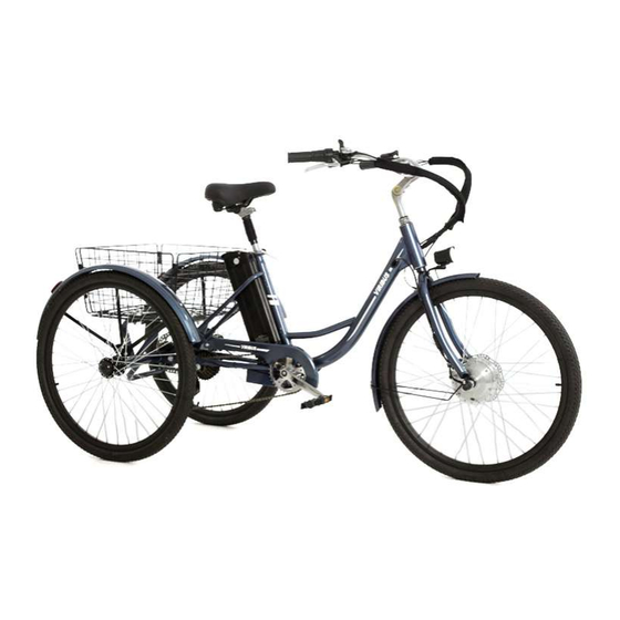
Product Diagram Main Parts Item Name Qty. Locking Pins Slats Rear Basket Frame Rear Frame with Rear Brake Disc Rear Reflectors Rear Wheel Caps Rear Fenders Rear Fender Stays Right Rear Wheel with D-Shaped Slot Left Rear Wheel with O-Shaped Slot Saddle Short Chain Long Chain... -
Page 9: Fasteners (Not Preinstalled)
Product Diagram Gear Shifter Display Panel Throttle Stem Steerer Tube Locking Handle Headset Seat Stay Head Tube Down Tube Front Fork Charging Port Seat Tube Battery Crank Arm Front Cog Control Hardware (Inside) Rear Cogs (Cassette) Rear Brake Disc Rear Derailleur Motor Front Brake Disc Fasteners (Not Preinstalled) -
Page 10: Tools
Product Diagram Tools Not Included but Helpful Item Name Qty. • Work Gloves Charger • Goggles Power Cord • Pliers Dual-Purpose Screwdriver Multifunctional Wrench 18 mm Wrench 22 mm Wrench M4 Hex Wrench M5 Hex Wrench M6 Hex Wrench Handlebars Downshift Lever Display Panel Gear Shifter... -
Page 11: Display Panel
Product Diagram Display Panel PAS Level Speed Battery Power Variable Display Control Buttons Toggles the variable display when pressed. Turns on/off the display panel when held. Increases the pedal assist level when pressed. Control Buttons Turns on/off the front light when held. Decreases the pedal assist level when pressed. -
Page 12: Preparation
Preparation 1. Prepare your work area for assembly, ensuring that it is spacious, clean, and well-lit. For best results, remove any objects that will not be used for assembly and restrict access to the area with prominent signs or barriers. Cluttered or dark areas may invite accidents. -
Page 13: Assembly
Complete assembly BEFORE activating the battery. For best results, remove the battery from the main frame BEFORE assembly. • To see these instructions in video form, go to our YouTube channel Viribus Bikes and search for “Viribus Electric Tricycle, ABE-L1AB/M1AB” Installing the Rear Wheels Important: The two rear wheels ARE different and should NOT be mixed up. - Page 14 Assembly 5. Remove the nut and washer from the O-shaped hub on the left side. 6. Slide the spacer inwards as shown. 7. Connect the wheel with the O-shaped slot (10) to the O-shaped hub. 8. Replace the washer and nut, tightening the nut in the same fashion. O-Shaped Slot Spacer O-Shaped Hub...
-
Page 15: Installing The Handlebars
Assembly Installing the Handlebars 1. Remove the protective cover underneath the steerer tube of the handlebars (16). 2. Loosen the bolt at the top of the steerer tube with the M6 hex wrench (R). 3. Slide the steerer tube into the head tube of the main frame (17) until your desired height is reached. -
Page 16: Connecting The Rear And Main Frames
Assembly Connecting the Rear and Main Frames 1. Turn the rear and main frames upside down. 2. Loosen the nuts and bolts on both sides of the main frame’s tail and the rear frame’s head. 3. Align the slots and bolts on the main frame with the bolts and slots on the rear frame. 4. -
Page 17: Installing The Long Chain
Assembly Installing the Long Chain 1. Raise the tension pulley on the rear derailleur. 2. Arrange the long chain (13) in an S shape, ensuring that the chain remains well fitted on both pulleys of the derailleur and one rear cog of the cassette. 3. -
Page 18: Installing The Short Chain
Assembly Installing the Short Chain 1. Find the short chain (12) and its three joint parts including a link, plate, and clip. 2. Place the short chain around the two rear freewheels. 3. Use the link and plate to join both ends of the chain, jamming the link pins into the slots. 4. -
Page 19: Connecting The Front Fender Stay To The Front Fender
Assembly 5. Pull the rear and main frames in opposite directions again until the short chain is taut but NOT overtight. 6. Tighten the nuts and bolts that connect the two frames completely with the multifunctional wrench (M). 7. Rotate the adjacent crank arm, testing that both the long and short chains move freely. Connecting the Front Fender Stay to the Front Fender 1. -
Page 20: Connecting The Front Fender To The Front Fork
Assembly Connecting the Front Fender to the Front Fork 1. Remove the nut and Phillips bolt from the top of the front fork with the multifunctional wrench and dual-purpose screwdriver. 2. Pass the front fender through the front fork as shown. 3. -
Page 21: Connecting The Front Fender Stay To The Front Fork
Assembly Connecting the Front Fender Stay to the Front Fork 1. Loosen the locking bolts on the protective bar between the front fork and then remove the bar from the fork. 2. Remove the Phillips bolts from the fork tips with the dual-purpose screwdriver. 3. -
Page 22: Installing The Front Light
Assembly Installing the Front Light 1. Turn the tricycle frame right side up slowly and carefully. Seek help from one or more persons if necessary. 2. Remove the nut and Phillips bolt at the top of the front fork again. 3. -
Page 23: Feeding The Front Brake Cable
Assembly Feeding the Front Brake Cable 1. Find the front brake cable located at the left side of the tricycle frame. 2. Loosen the locking nut of the front brake lever on the left handlebar. 3. Press and hold this lever, inserting the cable’s round metal head into the slot as shown. 4. -
Page 24: Installing The Front Brake Caliper
Assembly Installing the Front Brake Caliper 1. Unscrew the two hex bolts from the front brake caliper (19) preconnected to the front brake cable. 2. Fit the caliper onto its holder at the front fork’s left side, jamming the front brake disc into its slot as shown. -
Page 25: Feeding The Rear Brake Cable
Assembly Feeding the Rear Brake Cable 1. Find the rear brake cable located at the right side of the tricycle frame. 2. Loosen the locking nut of the rear brake lever on the right handlebar. 3. Press and hold this lever, inserting the cable’s round metal head into the slot as shown. 4. -
Page 26: Installing The Rear Reflectors
Assembly Installing the Rear Reflectors 1. Remove the nuts from the bolts on the rear reflectors (5). 2. Attach the rear reflectors to the rear fenders (7) using their bolts. 3. Secure these reflectors by replacing their nuts. 4. Tighten the nuts, using your pliers for best results. Rear Fender Rear Reflector Installing the Rear Fenders... -
Page 27: Installing The Rear Fender Stays
Assembly Installing the Rear Fender Stays 1. Fit the rear fenders over the rear wheels, with their reflectors facing backwards. 2. Align the rear fender stays with the side brackets on the rear frame, taking care NOT to allow the stays to touch the wheel tires or rims. 3. -
Page 28: Installing The Rear Basket
Assembly Installing the Rear Basket 1. Pull the tabs away from the provided locking pins (1) and place them nearby. 2. Unfold the rear basket frame (3) and align the slots on the edge of each side. 3. Connect the sides by inserting the locking pins into the slots. 4. -
Page 29: Installing The Rear Wheel Caps
Assembly 5. Remove the four sets of nuts, washers, and bolts preinstalled on the rear frame. 6. Fit the rear basket onto the top of the rear frame. 7. Place the slats (2) into the rear basket where their bolt holes are aligned with those on the rear frame. -
Page 30: Installing The Chain Guard
Assembly Installing the Chain Guard 1. Remove the two Phillips bolts preinstalled on the guard supports near the front and rear cogs with the dual-purpose screwdriver. 2. Place the chain guard (14) onto its supports and over the long chain as shown. 3. -
Page 31: Installing The Pedals
Assembly Installing the Pedals Important: The two pedals ARE different and should NOT be mixed up. The right pedal is marked with R and the left with L. 1. Attach the pedals (15) to the crank arms on the appropriate sides, screwing them into place. 2. -
Page 32: Connecting The Motor Cable
Assembly Connecting the Motor Cable 1. Slide the motor cable’s cap onto the nut at the right side of the front wheel hub. 2. Connect the motor cable to its signal cable from the handlebars. 3. Arrange the cable neatly throughout the rings along the front fork. Motor Cable Signal Cable Motor Cable... -
Page 33: Operation
Assembly Remember to take the following post-assembly actions to ensure optimal functionality for a safe and enjoyable riding experience. Failure to do so may result in unpleasant riding, property damage, and personal injury. Thoroughly check that ALL components and fasteners ARE undamaged and securely •... -
Page 34: Activating And Deactivating The Display Panel
Operation Activating and Deactivating the Display Panel 1. Ensuring that the battery is on, hold the button until the display panel activates. Note: ALWAYS perform this before using the throttle or pedal/push assist control. 2. To deactivate the panel, hold again until its screen shuts down. -
Page 35: Riding With Pedal Assist Control
Operation Riding with Pedal Assist Control The pedal assist system (PAS) is available when the battery and display panel are on. This requires you to continue using the pedals to keep the motor active but provides additional speed and strength as you ride. The PAS has 5 levels. -
Page 36: Riding The Manual Control
Operation Riding with Manual Control To ride your tricycle normally, you can select any of the following methods. Downshift the PAS level to 0. • • Turn off the display panel. Leave the key at the OFF position on the battery. •... -
Page 37: Charging
Charging In addition to the handlebar display, your tricycle’s current power level can be checked on the battery itself. Turn the key to ON and hold the power display button, seeing how many of the battery’s indicator lights turn on. Power Indicator Lights 3 lights indicate a full battery, while 1 light indicates a weak one. - Page 38 Charging 3. Hold the handle at the top of the battery, lifting the battery away from the tricycle. 4. Connect the provided charger (J) to its power cord (K) and the charging port at the opposite side of the key. 5.
-
Page 39: Maintenance
Maintenance DO NOT leave the display panel or battery on during cleaning, maintenance, or repair. Failure to follow this may result in accidental activation of the motor, posing a series of safety hazards. For the longest possible service life, disconnect the battery from the tricycle between uses. •... -
Page 40: Troubleshooting
ASAP! For a .pdf copy of the latest version of these instructions, use the appropriate app on your smartphone to scan the QR code to the right. ABE-L1AB-AB ABE-L1AB-AG ABE-L1AB-AP ABE-L1AB-AW ABE-M1AB-AB ABE-M1AB-AG ABE-M1AB-AP ABE-M1AB-AW Rev. 7 Feb. 2024...
Need help?
Do you have a question about the ABE-L1AB-AB and is the answer not in the manual?
Questions and answers
I **** attempting to pull the battery up, but it is held down with something I cannot see. How do I remove the battery
For best results, remove the battery from the main frame before assembly. To do this, detach the battery from the handlebars and turn it off before removing it.
This answer is automatically generated