Table of Contents
Advertisement
Quick Links
Advertisement
Table of Contents

Related Manuals for URC BREAKER-IQ QUICK-TRIP


Summary of Contents for URC BREAKER-IQ QUICK-TRIP
-
Page 3: Table Of Contents
BREAKER-IQ® Instruc�on Manual rev 1.0 www.u�lityrelay.com Contents Introduc�on and Product Overview ..... 3 6.8.2 User Session �meout ......23 Front View ............ 3 Storage ........... 23 Touchscreen Display ......... 3 6.10 Date & Time ........... 23 2.1.1 Screen saver ......... 3 6.11 System ............ - Page 4 BREAKER-IQ® Instruc�on Manual rev 1.0 www.u�lityrelay.com Figures Figure 45: Time and date entry screen ....23 Figure 1: Front View with main screen ...... 3 Figure 46: System screen ......... 23 Figure 2: Screen saver (main screen) ......3 Figure 47: Info screen ..........24 Figure 3: Side mini-USB port ........
-
Page 5: Introduc�On And Product Overview
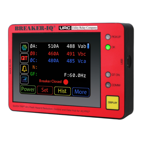
BREAKER-IQ® Instruc�on Manual rev 1.0 www.u�lityrelay.com 1.0 Introduc�on and Product Overview 2.1 Touchscreen Display The Breaker-IQ is a door or panel mounted display The 3.5” color touchscreen display is normally locked product exclusively designed for use with AC-PRO-II® from touch ac�ons and in screen saver mode. When trip units. -
Page 6: Display" Buton
AC-PRO-II. These connec�ons shall only be made to AC-PRO-II and with a cable supplied by URC. The Breaker-IQ includes a cable reten�on clip that physically secures the USB cable connec�on. The USB cable is for communica�ons and trip unit power. -
Page 7: Ac-Pro-Ii® To Breaker-Iq Cable
Note: The QT-Switch protrudes into the cubicle or panel that it is mounted on. Refer to Sec�on 4 for installa�on informa�on. URC also offers a surface- mount QT-Switch in a 1-gang enclosure. Contact URC for addi�onal informa�on. 3.4.1 Alternate (QT2-switch) Connection If a QT2-switch was already installed, it can s�ll be... -
Page 8: Output Connec�Ons
24-125VAC/DC, 0.2A. If the “load” (e.g. close coil) exceeds these ra�ngs, an addi�onal relay must be used. (an addi�onal relay is required for Close Breaker applica�ons). URC can supply or recommend these addi�onal relays. 3.6 Aux USB Port The Aux USB port is available for use with future... -
Page 9: Installa�On
BREAKER-IQ® Instruc�on Manual rev 1.0 www.u�lityrelay.com 4.0 Installa�on 4.1 Installation instructions and Items Included Included in the standard kit: Breaker-IQ unit, moun�ng hex nuts & washers, 5-foot cable for AC-PRO-II, and this Instruc�on Manual. Terminal block plugs for power, output #1, output #2, the USB cable clip and connector covers are already plugged into the unit connectors when it ships. -
Page 10: Electrical Connec�Ons And Diagrams
BREAKER-IQ® Instruc�on Manual rev 1.0 www.u�lityrelay.com 4.2 Electrical Connections and Diagrams An AC or DC power connec�on to Breaker-IQ is required, see Sec�on 4.3. The cable for connec�ng Breaker-IQ to AC-PRO-II consists of two (2) sets of connec�ons: a USB connec�on is used for communica�on and for providing power from the Breaker-IQ to the AC-PRO-II;... -
Page 11: Figure 15: Close Breaker Wiring Basic Diagram
Instruc�on Manual rev 1.0 www.u�lityrelay.com Close relay - various From close voltage ra�ngs From close circuit power Breaker-IQ power available from URC circuit power and trip unit (purchased separately) connec�ons are required but not shown in this Plug orange example. -
Page 12: Power Source
Aux USB port or to the side mini- Se�ngs sec�on of this manual for addi�onal USB port. If power only (without any URC USB informa�on about the “user session”. communica�on) is supplied to either of these USB ports, then the Breaker-IQ will automa�cally... -
Page 13: Screen Naviga�On With Ac-Pro-Ii
BREAKER-IQ® Instruc�on Manual rev 1.0 www.u�lityrelay.com 5.1 Screen Navigation with AC-PRO-II® When connected to AC-PRO-II®, tapping the When connected to AC-PRO-II, the Breaker-IQ (Configura�on menu) buton leads to the Security emulates the AC-PRO-II user interface and Code screen (if not already entered during the experience. -
Page 14: Metered Values
BREAKER-IQ® Instruc�on Manual rev 1.0 www.u�lityrelay.com 5.1.2 Metered values 5.1.3 Data Refresh Rates Breaker-IQ displays the following AC-PRO-II values: The Breaker-IQ automa�cally retrieves data from AC-PRO-II at the following approximate rates: • RMS Currents: Ia, Ib, Ic, In, Ig Metered values: refresh every 1-2 seconds •... -
Page 15: Figure 21: Ac-Pro-Ii® Screens Map On Breaker-Iq
BREAKER-IQ® Instruc�on Manual rev 1.0 www.u�lityrelay.com When connected to AC-PRO-II®, the main screen displays the “Power”, “Set” (Se�ngs), “Hist” (Trip History), and “More” butons. These butons allow naviga�on to most AC-PRO-II screens on the Breaker-IQ screen. See the figure below for an example of the screen naviga�on map. Actual screens will depend on the firmware version of the connected AC-PRO-II. -
Page 16: Screen Naviga�On With Ac-Pro
BREAKER-IQ® Instruc�on Manual rev 1.0 www.u�lityrelay.com 5.2 Screen Navigation with AC-PRO® 5.3 Screen Navigation Without Trip Unit Connection Though the Breaker-IQ was designed for AC-PRO-II, it can be used with AC-PRO trip units (limited If a trip unit is not connected to BREAKER-IQ, the func�onality). -
Page 17: Quick-Trip® Arc Flash Reduc�On (Erms)
6.2 Quick-Trip® Arc Flash Reduction (ERMS) IMPORTANT: the operator must confirm the Breaker-IQ Quick-Trip (QT) LED is ON. This posi�vely Quick-Trip system is a manually controlled Arc Flash indicates that the connected trip unit is in Quick-Trip Reduc�on system, more generally known as an mode. -
Page 18: Breaker Control
. The Security Code entry screen �me. Recording of the breaker mechanism �me is will appear (unless the Security Code has already part of URC’s Sluggish Breaker Detec�on® feature. been successfully entered during the same user These trips are logged as “Safe-T-Trip” trip type. -
Page 19: Delayed Close
“Close Bkr”.) 4. Ensure all safety precau�ons are taken and Contact URC for close relay op�ons. confirm you want to Close the breaker by tapping “Yes”. (see screenshot in this Op�on 2: AC-PRO-II is wired into the close circuit: sec�on). -
Page 20: Graphical Data Screens
BREAKER-IQ® Instruc�on Manual rev 1.0 www.u�lityrelay.com 6.4 Graphical Data Screens 6.4.1 Trip History The Breaker-IQ® is capable of displaying trip history The Breaker-IQ is capable of displaying all of the AC- waveforms and on-demand waveforms that are PRO-II Trip History data including waveforms. stored in the AC-PRO-II. -
Page 21: Waveforms (On-Demand)
BREAKER-IQ® Instruc�on Manual rev 1.0 www.u�lityrelay.com 6.4.2 Waveforms (on-demand) The Breaker-IQ® is also capable of ini�a�ng and displaying “on-demand” waveform capture from AC- PRO-II. • The AC-PRO-II saves five (5) cycles of “on- demand” waveform data. • The data is saved to AC-PRO-II non-vola�le memory. -
Page 22: Wireless Comm & Se�Ngs
BREAKER-IQ® Instruc�on Manual rev 1.0 www.u�lityrelay.com 6.5 Wireless Comm & Settings A USB Wireless dongle is available from URC. This device can be used to allow a Windows PC to The BREAKER-IQ® is capable of Wireless wirelessly communicate with BREAKER-IQ. -
Page 23: Alarms & Status Informa�On
In addi�on, if the condi�on is a type that can be reset by the user, the 7. Ensure URC USB Wireless dongle is plugged op�on to reset it will be offered. into a USB port on your Windows PC. -
Page 24: Outputs & Se�Ngs
BREAKER-IQ® Instruc�on Manual rev 1.0 www.u�lityrelay.com 6.7 Outputs & Settings The Outputs screen can be accessed from the Configura�on Menu. See Figure 20. Successful Security Code entry (last 4 digits of Breaker-IQ serial number) is required to access Output se�ngs. See the specifica�ons sec�on for output ra�ngs. -
Page 25: User Session �Meout
BREAKER-IQ® Instruc�on Manual rev 1.0 www.u�lityrelay.com 6.8.2 User Session timeout 6.10 Date & Time The user session �meout se�ng can be set between The Breaker-IQ syncs up to the connected trip unit’s 30 - 300 seconds. The default se�ng is 120 seconds. date &... -
Page 26: Informa�On Screen
Figure 47: Info screen 6.13 Firmware 6.13.1 Breaker-IQ® firmware The Breaker-IQ firmware can be updated in the field using a Windows PC, URC’s InfoPro-AC so�ware, and a mini-USB cable. Contact URC for addi�onal informa�on. 6.13.2 AC-PRO-II® firmware Breaker-IQ is compa�ble with all released versions of AC-PRO-II firmware. -
Page 27: Specifica�Ons
BREAKER-IQ® Instruc�on Manual rev 1.0 www.u�lityrelay.com 8.0 Specifica�ons 8.1 Drawings and Dimensions Dimensions are in inches. Figure 48: Front View drawing Figure 49: Rear view drawing Page 25... -
Page 28: Tests
first �me, it is possible that a trip alarm (status condi�on) from a previous trip may s�ll be present. Simply reset the trip alarm using the Breaker-IQ. Contact URC for more informa�on. Figure 50: Side view drawing 8.2 Tests The Breaker-IQ was tested by an independent...
Need help?
Do you have a question about the BREAKER-IQ QUICK-TRIP and is the answer not in the manual?
Questions and answers