
Subscribe to Our Youtube Channel
Related Manuals for Uniks C58


Summary of Contents for Uniks C58
- Page 1 Digital Trms AC/DC Clamp Meter User Manual V.1.0 27.11.2023 © Copyright Uniks Srl...
- Page 2 REGISTER YOUR PRODUCT www.uniks.it The registration of your products will allow you to stay informed about news, take advantage of advantageous discounts dedicated to you for the purchase of accessories and products for your daily work. Registration is free...
-
Page 3: Table Of Contents
1. Safety Information ............4 Please follow the safety operation guidelines to ensure safe use of the meter........4 1.1 Preparations ............4 1.2 Symbol .............. 5 1.3 Maintenance ............. 6 2. Description..............7 2.1 Part Name ............7 2.2 Instructions to rotary switch ...... -
Page 4: Safety Information
1. Safety Information WARNING Special attention shall be paid when using the meter, improper use might cause an electric shock or damage the meter. During use, it is necessary to follow the usual safety regulations and fully comply with the safety measures specified in the user manual. To fully make use of the functions of the meter and ensure safe operation, please carefully read and follow the instructions of this manual. -
Page 5: Symbol
1.1.2 After received the meter, check if it has been damaged during the delivery. 1.1.3 After storage and shipment under poor conditions, inspect and confirm whether the meter is damaged. 1.1.4 The pen must be in good condition. Before use, check the pen to see if any damage to the insulation and if the metal wire of the wire exposed. -
Page 6: Maintenance
1.3 Maintenance 1.3.1 Please do not attempt to open the bottom case to adjust or repair the meter. Such operation could only be performed by technicians who are fully aware of the meter and the risk of electric shock. 1.3.2 Before opening the meter case or battery cover, the pen should be removed from the tested line. -
Page 7: Description
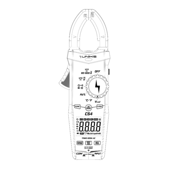
2. Description 2.1 Part Name Current clamp head: used for measuring current Rotary switch Function button Display screen Input socket Function button Trigger Non-contact voltage detecting & inducing area... -
Page 8: Instructions To Rotary Switch
2.2 Instructions to rotary switch Meter OFF position 60A/600A range of AC/DC current measurement. AC/ DC Voltage measurement Resistance / Continuity / Diode / Capacitance Frequency / Duty Temperature measurement Low resistance voltage measurement 2.3 LCD display... - Page 9 Automatic shutdown indication Battery low voltage indication Inrush current measurement mode Auto range Relative measurement mode Maximum measurement indication Minimum measurement indication Low pass filter indicator Continuity indication Diode measurement mode Data negative sign 、 DC、AC Data hold status Duty cycle symbol 、...
-
Page 10: Specification
3. Specification The meter should specify one year as a cycle to re- calibrate in the conditions of 18℃ ~ 28℃ and relative humidity less than 75%. 3.1 Overview • Automatically select measurement function and range. • Overload protection for the whole measurement range. -
Page 11: Technical Index
• Temperature coefficient: < 0.1×accuracy /℃ Working temperature : 18℃ ~ 28℃ • Storage temperature : -10℃ ~ 50℃ • 3.2 Technical Index When measuring current,place the conductor to the center of the clamp head. If not, it can increase ±1.5% position deviation to the maximum 3.2.1 DC current... - Page 12 3.2.2 AC Current Range Resolution Accuracy 0.01A (2.5% reading +5 digits) 600A 0.1A - Minimum input value of AC current : 0.1A(rms) - Maximum input value of AC current : 600A(rms) - Frequency range:45Hz~1000Hz 3.2.3 AC Voltage Range Resolution Accuracy 0.001V (0.8% reading +5 digits)...
-
Page 13: Frequency / Duty
3.2.4 DC Voltage Range Resolution Accuracy 0.001V 0.01V (0.5% reading +5 digits) 600V 0.1V 1000V - Minimum input value of DC voltage:1mV - Maximum input value of DC voltage:1000V 3.2.5 Frequency / Duty 3.2.5.1 By A Range(from current clamp): Range Resolution Accuracy 100Hz... - Page 14 3.2.5.2By V Range: Range Resolution Accuracy 100Hz 0.01Hz 1000Hz 0.1Hz (1.0% reading +5 digits) 10kHz 0.001kHz 100kHz 0.01kHz 500kHz 0.1kHz - Frequency input range:10Hz~500kHz - Input signal range:≥ 0.8V AC voltage(rms) 3.2.5.3 By Hz/%Range: Range Resolution Accuracy 10Hz 0.001Hz 100Hz 0.01Hz 1kHz (0.5% reading +5 digits)...
- Page 15 3.2.6 Continuity Range Resolution Functions If resistance is lower than 30, then the beeper in the meter may 1 sound. The circuit voltage is about - Overload protection:1000V DC or AC(rms) 3.2.7 Diode Range Resolution Functions Displays approximate value of diode forward voltage Forward 0.001V voltage.
- Page 16 3.2.9 Capacitance Range Resolution Accuracy 6.000nF 0.001nF 100.0nF 0.1nF 1.000uF (4.0% reading +5 digits) 10.00uF 10nF 100.0uF 100nF 1.000mF (4.0% reading +5 digits) 10.00mF 10uF (5.0% reading +5 digits) 100mF 100uF - Overload protection:1000V DC or AC(rms) 3.2.10 Temperature Range Resolution Accuracy -20~1000℃(...
-
Page 17: Operation Guide
4. Operation Guide 4.1 Data Hold / Light During the measuring process, if the readings are required to hold, slightly press “ ” button,the display value will be locked, slight press “ ” button again to cancel data hold. Press and hold for more than 2 seconds to turn on or off the lighting, and it will automatically turn off after about 1 minute. -
Page 18: Manual Range
3)When turn the meter on, hold the “ ” button at the same time,then the auto power off function will be canceled. 4.4 Manual Range Press the“ ”button to enter manual range mode, press the button again to switch to the current range, press and hold to exit manual range mode. -
Page 19: Ac / Dc Voltage Measurement
4.7 AC / DC voltage measurement 1)Turn rotary switch to AC/DC voltage, press “ ” button to shift between AC and DC voltage measurement mode, and connect the probe to the measured signal. 2)In DC mode, the red probe is connected to the positive pole of the measured signal and the black probe is connected to the negative pole of the measured signal. -
Page 20: Low Resistance Voltage Measurement
4.8 Low resistance voltage measurement Turn rotary switch to “ ”,press “ ” button to switch between AC and DC voltage measurement mode to connect the probe to the measured signal. -
Page 21: Resistance / Continuity / Diode / Capacitance Measurement
Note:In low resistance measurement mode,the input impedance is 300kΩ,the longest measurement time shall not be more than 1 minute 4.9 Resistance / Continuity / Diode / Capacitance measurement Turn rotary switch to “ ”,press “ ” button to switch to select the resistance, continuity,diode, capacitance measurement function. - Page 22 Note:When measuring large capacitance, the capacitance should be fully discharged before measurement, otherwise it may introduce significant errors.
-
Page 23: Frequency / Duty
4.10 Frequency / Duty Turn rotary switch to “ ”,press “ ” button to switch to select the frequency or duty measurement. -
Page 24: Temperature Measurement
4.11 Temperature measurement Turn rotary switch to “ ”,insert thermocouple probe into input socket, with the positive pole of the probe being connected to red input terminal. The primary display panel will show the measured temperature,slightly press “ ” button to switch the unit for measuring temperature. 4.12 Non-contact Voltage Detection(NCV)... -
Page 26: Maintenance
5. Maintenance 5.1 Replace Battery WARNING Before opening the battery cover of the meter, the test lead shall be removed from the measuring circuit first to prevent the risk of electric shock. 1) If “ ” symbol appears, it means the batteries shall be replaced. -
Page 27: Replace Test Lead
5.2 Replace Test Lead WARNING When replacing the pens, the new ones shall be of the same or in equal level. The pens must be in good condition, and level of the Test Lead is: 1000V 10A. Note:If the insulation layer of the test lead is damaged, such as the metal wire of the cable is exposed, then the pen must be replaced. -
Page 28: Accessories
6. Accessories Test Leads Level:1000V 10A 1) Use Manual 2) Battery 1.5V AAA Battery 3) Cloth bag 4) K-Type Thermocouple Probe 5) 7. ASSISTANCE 7.1 WARRANTY CONDITIONS This instrument is warranted against defects in materials and workmanship, in accordance with the general terms and conditions. -
Page 29: Assistance
The warranty does not apply in the following cases: • Repair and / or replacement of accessories and battery (not covered by warranty). • Repairs made necessary because of a misuse of the instrument or of its use with no compatible devices. •... - Page 30 of the cables and replace them if necessary. If the instrument continues to manifest malfunctions check if the procedure of use of the same is in accordance with what is indicated in this manual. If the instrument is to be returned to the after - sales service or to a dealer transportation is borne by the customer.
Need help?
Do you have a question about the C58 and is the answer not in the manual?
Questions and answers