Table of Contents
Advertisement
Quick Links
Advertisement
Table of Contents

Related Manuals for Uniks C6


Summary of Contents for Uniks C6
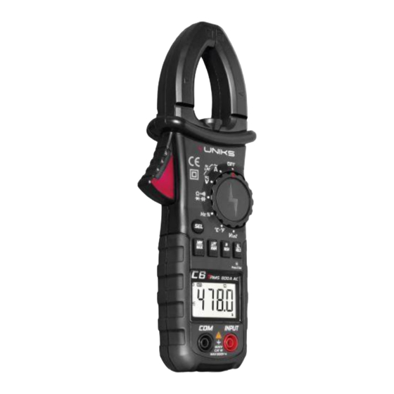
- Page 1 TRMS Digital Clamp Meter 600A AC V1.0 29.11.2022...
- Page 3 REGISTER YOUR PRODUCT www.uniks.it The registration of your products will allow you to stay informed about news, take advantage of advantageous discounts dedicated to you for the purchase of accessories and products for your daily work. Registration is free...
-
Page 4: Table Of Contents
1. Summary ............5 1.1. Safety Standards ..............5 1.2 Safety Signs ................5 2. Instrument Schematic ........7 3. Instructions ............10 3.1 AC and DC voltage measurement ........10 3.2 AC voltage and frequency measurement ......10 3.3 DC voltage measurement ............. 11 3.4 AC current measurement ............ -
Page 5: Summary
1. Summary Uniks C6 digital AC clamp meter is a stable, safe and reliable instrument. The circuit of the instrument takes integrated circuit as the core and is equipped with a full range overload protection circuit. It has a novel... - Page 6 Cautions • Please read the instructions carefully before using the instrument, and pay special attention to the contents of " ". Please follow the operating instructions of " ". • Ensure that the instruments and probes coming with the package meet the requirements of safety standards.
-
Page 7: Instrument Schematic
2. Instrument Schematic 1. AC current clamp Used for sampling AC current. 2. Safety barrier Effectively keep the operator from accidentally taping the live conductor during the current measurement 3. Function range switch... - Page 8 Used for selecting various functions and range positions. 4. Data-hold key/Backlight-display button • Tap the "BL/HOLD" button, the final reading will be maintained on the display and " " is displayed. Tap the "BL/HOLD" button again, and the instrument will return to the normal measurement state. •...
- Page 9 • Press and hold this key for more than 2 seconds during the manual range to switch back to the automatic range. • During the AC current and AC voltage automatic measuring, press and hold the "LPF/RAN" button for about 2 seconds to turn on or off the LPF mode.
-
Page 10: Instructions
12. Trigger Press the trigger and the clamp opens: release the trigger and the clamp automatically closes. 13. Clamp meter light • Press and hold the "INRUSH" button for more than 2 seconds to turn the light on or off. •... -
Page 11: Dc Voltage Measurement
• Tap the "LPF/RAN" button to switch the range of AC voltage. • When in the AC voltage automatic measurement, press and hold the "LPF/RAN" button for about 2 seconds to turn on or off the LPF filter function. The filter attenuation frequency point is about -0.94dB at 1kHz. -
Page 12: Resistance Measurement
4. Tap "INRUSH" button to start the inrush current measurement function. Caution: △ It is impossible to measure if clamping multiple wires at the same time. △ If the measured current range is unknown in advance, please set the function range switch to the maximum range, and then gradually reduce the range until a satisfactory resolution is achieved. -
Page 13: Diode Measurement
3.6 Diode measurement 1. Insert the red probe into the "INPUT" terminal and the black probe into the "COM" terminal. At this time, the polarity of the red probe is "+" and the polarity of the black probe is "-". 2. -
Page 14: Frequency And Duty Ratio Measurement
maximum range, the instrument with higher range shall be selected. Before measuring the in-circuit capacitance, the power supply of the tested circuit must be cut off and all capacitors must be fully discharged. When measuring the polar capacitance, the red probe is connected to the positive terminal of the capacitance. -
Page 15: Low Impedance Ac/Dc Voltage Measurement
3. Read the measured temperature value. 3.11 Low impedance AC/DC voltage measurement 1. Set the function range switch to " " position. 2. Tap the "SEL" button to switch between AC and DC voltage measurement modes and connect the probes to the measured signal. Caution: When measuring... - Page 16 Caution: When measuring current, please place the conductor to be measured in the center of the clamp. If not, the position error of 1.5% to the maximum can be increased.
-
Page 17: Electrical Specification
4. Electrical Specification DC voltage Range Resolution Accuracy 0.001V 0.01V ± (0.5% reading+3 digits) 600V 0.1V Input impedance: 10MΩ. Maximum allowable input voltage: 600V DC or 600V AC RMS. AC voltage Range Resolution Accuracy 0.001V 0.01V ± (0.8% reading+5 digits) 600V 0.1V Input impedance: 10MΩ. - Page 18 Resistance Range Resolution Accuracy 600 0.1 6k 0.001k 60k 0.01k ± (1.0% reading+3 digits) 600k 0.1k 6M 0.001M 60M 0.01M ± (2.0% reading+3 digits) Overload protection: 600V DC or 600V AC RMS. Diode test Range Resolution Accuracy Displays the approximate value of the forward voltage drop 0.001V (The open circuit voltage is about 3.0V)
- Page 19 Capacitance Range Resolution Accuracy 10nF 0.001nF 100nF 0.01nF ± (3.0% reading+5 digits) 1µF 0.1nF 10µF 100µF 0.01µF 0.1µF ± (4.0% reading+5 digits) 10mF 0.001mF 100mF 0.01 mF ± (5.0% reading+5 digits) Overload protection: 600V DC or 600V AC RMS. Frequency Range Resolution Accuracy...
- Page 20 Duty ratio Range Resolution Accuracy 1~99 % 0.1% ± (3.0% reading+2 digits) Overload protection: 600V DC or 600V AC RMS. Temperature Range Resolution Accuracy -20℃~1000℃ 1℃/1℉ ± (1.0% reading+2 digits) (-4℉~1832℉) Overload protection: 600V DC or 600V AC RMS.
-
Page 21: General Specification
5. General Specification • Automatic selection of the measuring range of the measuring function. • Full range overload protection. • The maximum allowable voltage between the measuring end and the ground: 600V DC or 600V AC. • CAT III 600V •... -
Page 22: Maintenance
6. Maintenance • Before opening the back cover of the instrument, the probes should be disconnected from the measuring circuit. • Only a damp cloth and a small amount of detergent can be used to clean the instrument. Do not use chemical solvents or abrasives to wipe the case. -
Page 23: Battery Replacement
7. Battery Replacement WARNING To avoid electric shock, disconnect the probes before opening the battery cover and do not connect to any circuit under test or input signal. Only replace batteries of the same model or electrical specification If the undervoltage symbol, " ", appears, it means that the battery is low (the deviation of the measured value in this state is greater) and needs to be replaced. -
Page 24: Warranty Conditions
8. WARRANTY CONDITIONS This instrument is warranted against defects in materials and workmanship, in accordance with the general terms and conditions. During the warranty period, defective parts can be replaced, but the manufacturer reserves the right to repair or replace the product. If the instrument is to be returned to the after - sales service or to a dealer transportation is borne by the customer. -
Page 25: Assistance
The content of this manual may not be reproduced in any form without the permission of the manufacturer. Our products are patented and their trademarks. The manufacturer reserves the right to change specifications and prices if this is due to technological improvements. - Page 28 Uniks Srl https://www.uniks.it info@uniks.it Via Vittori 57 48018 Faenza (RA), Italy 0546.623002 0546.623691...
Need help?
Do you have a question about the C6 and is the answer not in the manual?
Questions and answers