Table of Contents
Advertisement
Quick Links
Advertisement
Table of Contents

Subscribe to Our Youtube Channel
Related Manuals for Uniks SKILL


Summary of Contents for Uniks SKILL
- Page 1 SKILL Intelligent Digital AC/DC Clamp Meter User Manual...
- Page 2 REGISTER YOUR PRODUCT www.uniks.it The registration of your products will allow you to stay informed about news, take advantage of advantageous discounts dedicated to you for the purchase of accessories and products for your daily work. Registration is free...
-
Page 3: Table Of Contents
1. Safety Information ......... 5 1.1 Preparations ........5 1.2 Symbol ..........6 1.3 Maintenance ........6 2. Description ............8 2.1 Part Name ............8 2.2 Instructions to rotary switch ... 9 2.3 LCD display .......... 9 3. Specification ..........10 3.1 Overview .......... - Page 4 4.8 AC/DC current measurement ..19 4.9 AC/DC voltage measurement ..20 4.10 Resistance/ Continuity Measurement ........... 21 4.11 Dual measurement display ..22 5. Maintenance ..........25 5.1 Replace Battery......... 25 5.2 Replace Pens ........26 6. Accessories ............. 26 7.
-
Page 5: Safety Information
Safety Information WARNING Special attention shall be paid when using the meter, improper use might cause an electric shock or damage the meter. General safety procedures shall be followed during the use safety measures regulated instruction manual shall completely respected. To fully make use of the functions of the meter and ensure safe operation, please carefully read and follow the use method of... -
Page 6: Symbol
1.1.4 The pen-shape meter must be in good condition. Before use, check the pen-shape meter see if any damage to the insulation, if the metal wire of the cable is bare 1.2 Symbol Note (important security information, see the Instruction Manual) Able to be used on dangerous electrified conductors. - Page 7 should be removed from the circuit being measured. 1.3.3 o avoid electric shock that might be caused by erroneous readings, when the meter displays “ ” symbol, the battery should be replaced immediately. 1.3.4 Use a damp cloth and mild detergent to clean the meter, do not use abrasive cleaning agents or solvents 1.3.5 Power supply of the meter should be...
-
Page 8: Description
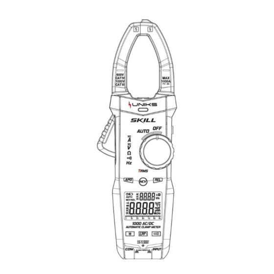
2. Description 2.1 Part Name 1. Current clamp head: used for measuring current 2. Rotary switch 3. Function button 4. Display screen 5. Input socket 6. Function button 7. Trigger 8 Non-contact voltage detecting & inducing area... -
Page 9: Instructions To Rotary Switch
2.2 Instructions to rotary switch Meter OFF position Automatic range measurement mode 2.3 LCD display Automatic shutdown indicate Battery low voltage indication Auto range Relative measurement mode Non-contact voltage detection Connected disconnect indicate... -
Page 10: Specification
Diode measurement mode data negative sign 、 DC、AC Readings hold status Duty cycle symbol 、 Hertz, Kilohertz low pass filter indicator 、 Current value unit:mA、A 、 Voltage value unit:mV、V 、 、 Ohm,Kilohm, Megohm (resistance) 3. Specification The meter should specify one year as a cycle to re-calibrate in the conditions of 18℃... -
Page 11: Technical Index
− Maximum display value: 6000 digits. − Polar indication: automatically indicate,‘-’ means negative polarity − Over range Indication: ‘0L’ or ‘-0L’ − Sampling time: about 3 times/s,analog strip 10 times/s. − Unit display: with function and quantity of electricity unit display −... - Page 12 3.2.1 AC Current TRMS Range Resolution Accuracy 0.01A (2.5% reading +8 600A 0.1A digits) 1000A - Minimum input value of AC current:0.5A (RMS) - Maximum input value of AC current:1000A (RMS) - Frequency range:45Hz~65Hz...
- Page 13 3.2.2 DC current Range Resolution Accuracy 0.01A (3.0% reading+10 600A 0.1A digits) 1000A - Minimum input value of DC current:0.5A - Maximum input value of DC current:1000A 3.2.3 AC Voltage TRMS Range Resolution Accuracy 0.001V (0.8% reading +5 0.01V digits) 600V 0.1V - Minimum input value of AC voltage:1.0V...
- Page 14 3.2.4 DC Voltage Range Resolution Accuracy 0.001V (0.5% reading +5 0.01V digits) 600V 0.1V - Minimum input value of DC voltage:0.5V - Maximum input value of DC voltage:600V 3.2.5 Frequency 3.2.5.1 Clamp head frequency measurement (Via gear A): Range Resolution Accuracy 60Hz 0.1Hz...
- Page 15 3.2.6 Resistance Range Resolution Accuracy 6k 0.001k 60k 0.01k ( 0.8% reading 600k 0.1k +3 digits) 6M 0.001M 10M 0.01M - Overload protection:600V DC or AC(RMS) 3.2.7 Line on-off test Range Resolution Functions If the resistance of circuit being measured is less than 1...
-
Page 16: Operation Guide
4. Operation Guide 4.1 Readings Hold During the measuring process, if the readings are required to hold, slightly press “ ” button ,the display value will be locked, slight press “ ” button again to cancel readings hold. 4.2 Backlight / Light In the process of measurement, if the ambient light is too dim, causing reading difficulties, press "... -
Page 17: Measurement Preparations
3)Press " " button to cancel or turn on the auto power-off function. 4.5 Measurement Preparations 1)Turn the transfer switch, turn on the power. If the battery voltage is low (about ≤ 3.5V), the LCD will show “ ”, then the battery shall be replaced 2 )... -
Page 18: Non-Contact Voltage Detection (Ncv)
4.7 Non-contact Voltage Detection (NCV) Press and hold " " key for more than 2 seconds, NCV function is enabled and the meter LCD will display. -
Page 19: Ac/Dc Current Measurement
When the NCV sensing area of the meter is close to the measured cable, the charged cable can be judged by the buzzer sound and the LED indicator on the panel. In NCV detection mode, the meter does not measure voltage, resistance, or current at the same time. -
Page 20: Ac/Dc Voltage Measurement
4.9 A voltage measurement C/DC Turn rotary switch to " ", then connect the meter probe to the measured voltage signal. 1)When the measured signal is DC voltage and the voltage value is ≥ 0.5V, the meter will display the current measured DC voltage value. -
Page 21: Resistance/ Continuity Measurement
resistance value and display the internal resistance value of the measured signal. 4.10 Resistance / Continuity Measurement Turn rotary switch to " " level and connect the meter probe to the measured resistor. When the measured resistance is <50Ω, the meter buzzer will buzz; when the measured resistance is >10M... -
Page 22: Dual Measurement Display
-". 4.11 Dual measurement display The meter can also measure and display the voltage or resistance value while measuring and displaying the current value by turn rotary switch to " ". 1)Hold the trigger, open the clamp head, and clamp one. Cable of the measured circuit,... - Page 23 when the measured signal is > 0.5A (0.5A RMS for AC current and 0.5A for DC current), the meter secondary display shows the measured current value. 2)Connect the meter probe to the measured signal, when the measured AC signal RMS value is ≥...
- Page 24 4)When the measured resistance is <50Ω, the meter buzzer will buzz; when the measured resistance is >10M , the meter will display "----".
-
Page 25: Maintenance
5. Maintenance 5.1 Replace Battery WARNING Before opening the battery cover of the meter, the pen-shape meter shall be moved from the measuring circuit first to prevent the risk of electric shock 1) If “ ” symbol appears, it means the battery shall be replaced 2) Screw the fastening screws of the meter battery cover and move away. -
Page 26: Replace Pens
5.2 Replace Pens WARNING When replacing the pens, the new ones shall be of the same or in equal level. The pens must be in good condition, and level of the pens is: 1000V 10A. Note: If the insulation layer of the pens is damaged, such as the metal wire of the cable is exposed, then it must be replaced. -
Page 27: Assistance
7. ASSISTANCE 7.1 WARRANTY CONDITIONS This instrument is warranted against defects in materials and workmanship, in accordance with the general terms and conditions. During the warranty period, defective parts can be replaced, but the manufacturer reserves the right to repair or replace the product. If the instrument is to be returned to the after - sales service or to a dealer transportation is borne by the customer. -
Page 28: Assistance
Repairs made necessary due to improper • packaging. Repairs made necessary due to work • carried out by unauthorized personnel. Modification of the instrument without the • explicit permission of the manufacturer. Use not provided for in the specifications • of the instrument or in the instruction manual. - Page 29 of the same is in accordance with what is indicated in this manual. If the instrument is to be returned to the after - sales service or to a dealer transportation is borne by the customer. The shipment must, however, be agreed.
- Page 32 Uniks Srl Via Vittori 57 48018 Faenza (RA), Italy 0546.623002 0546.623691...
Need help?
Do you have a question about the SKILL and is the answer not in the manual?
Questions and answers