
Subscribe to Our Youtube Channel
Related Manuals for YitaHome FTLFFT-0003


Summary of Contents for YitaHome FTLFFT-0003
- Page 1 ASSEMBLY INSTRUCTIONS ZSJX-V2 FTLFFT-0003 FTLFFT-0004 FTLFFT-0005 FTLFFT-0006 FTLFFT-0013 FIREPLACE TV STAND...
- Page 2 ASSEMBLY INSTRUCTIONS 1. Two or more people are needed to complete the installation. 2. Please protect the wires and remote control accessories from damage during installation. 3.Professional installation is highly recommended. 4.Assemble on a flat, clean and soft surface. Item Item Reference Image Qty.
- Page 3 ASSEMBLY INSTRUCTIONS Item Item Reference Image Qty. Reference Image Qty.
- Page 4 ASSEMBLY INSTRUCTIONS...
- Page 5 ASSEMBLY INSTRUCTIONS 2pcs 4pcs...
- Page 6 ASSEMBLY INSTRUCTIONS 4pcs 8pcs 180°...
- Page 7 ASSEMBLY INSTRUCTIONS 8pcs...
- Page 8 ASSEMBLY INSTRUCTIONS 8pcs 8pcs...
- Page 9 ASSEMBLY INSTRUCTIONS 4pcs...
- Page 10 ASSEMBLY INSTRUCTIONS 4pcs...
- Page 11 ASSEMBLY INSTRUCTIONS 16pcs 16pcs...
- Page 12 ASSEMBLY INSTRUCTIONS 4pcs 2pcs Note: If plates 12-9 and 12-10 are installed correctly, there should be some space remaining to the edge. If the plates extend all the way to the edge, it indicates that both plate 9 and plate 10 were installed incorrectly.
- Page 13 ASSEMBLY INSTRUCTIONS 4pcs 16pcs 8pcs...
- Page 14 ASSEMBLY INSTRUCTIONS 12pcs...
- Page 15 ASSEMBLY INSTRUCTIONS 16pcs 8pcs 8pcs...
- Page 16 ASSEMBLY INSTRUCTIONS 8pcs...
- Page 17 ASSEMBLY INSTRUCTIONS 25pcs One decorative screw cover (L) for each visible eccentric wheel (B)
- Page 18 ASSEMBLY INSTRUCTIONS 36pcs Note: Tighten the two screws on the top of each back plate first.
- Page 19 ASSEMBLY INSTRUCTIONS 4pcs Thread the socket plug through the hole in plate #15 and #16. 1.Connect the plugs on two-end lamp strip to the two ends of part N. 2.Then fix the light strip connection cable to plate #7. 3.Insert the USB interface of part T into the plug.
- Page 20 ASSEMBLY INSTRUCTIONS 2pcs 8pcs...
- Page 21 ASSEMBLY INSTRUCTIONS 8pcs 4pcs 2pcs...
- Page 22 ASSEMBLY INSTRUCTIONS 16pcs In order to ensure the consistent spacing between the upper and lower door joints, the lower part of the door hinge should be installed first, followed by the upper part. Adjust the distance between the cabinet door and the frame here. Adjust the lateral distance between the cabinet door and the frame here.
- Page 23 ASSEMBLY INSTRUCTIONS 4pcs 2pcs...
- Page 24 ASSEMBLY INSTRUCTIONS 2pcs 2pcs...
- Page 25 ASSEMBLY INSTRUCTIONS 2pcs 2pcs...
- Page 26 ASSEMBLY INSTRUCTIONS Simply push the pull-out cabinet inward and it will be automatically secured in place. To pull it out, flatten part Q (plastic fixing clip) to first unlock the position.
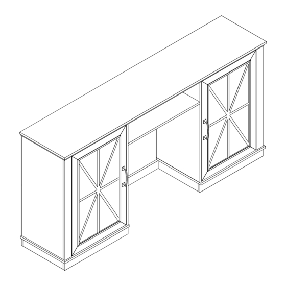
- Page 27 ASSEMBLY INSTRUCTIONS Installation Completed...
- Page 28 Pure & Easy...
Need help?
Do you have a question about the FTLFFT-0003 and is the answer not in the manual?
Questions and answers