Advertisement
Quick Links
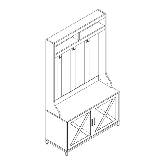
ASSEMBLY INSTRUCTIONS
GZHL-V1
FTLFCR-6007
Coat rack
Notice:
1.Follow the installation instructions. Please confirm all accessories are preset before installation.
2.Do not fully tighten the screws during initial assembly.Fully tighten screws only once all pieces
which are correctly assembled.
3.If you encounter any problems during installation, please contact our customer service.
1
Advertisement

Related Manuals for YitaHome FTLFCR-6007


Summary of Contents for YitaHome FTLFCR-6007
- Page 1 ASSEMBLY INSTRUCTIONS GZHL-V1 FTLFCR-6007 Coat rack Notice: 1.Follow the installation instructions. Please confirm all accessories are preset before installation. 2.Do not fully tighten the screws during initial assembly.Fully tighten screws only once all pieces which are correctly assembled. 3.If you encounter any problems during installation, please contact our customer service.
- Page 2 ASSEMBLY INSTRUCTION...
- Page 3 ASSEMBLY INSTRUCTION PICTURE SIZE PICTURE SIZE M6*30 M6*40 ST7*40 ST3.5*14 M6*40 ST3.5*14 8*35 ST3*14 M4*18...
- Page 4 ASSEMBLY INSTRUCTION...
- Page 5 ASSEMBLY INSTRUCTION...
- Page 6 ASSEMBLY INSTRUCTION STEP 1 M6*40 STEP 2 M6*40...
- Page 7 ASSEMBLY INSTRUCTION STEP 3 When installing the No. 13 board, it should be noted that the reverse side also needs to install D screws at the same time. M6*40 STEP 4 Pay attention to the orientation of the holes. M6*40...
- Page 8 ASSEMBLY INSTRUCTION STEP 5 Pay attention to the orientation of the holes. M6*40 STEP 6 M6*40...
- Page 9 ASSEMBLY INSTRUCTION STEP 7 STEP 8 Pay attention to the orientation of the holes. ST7*40...
- Page 10 ASSEMBLY INSTRUCTION STEP 9 STEP 10 We need to divide accessory H into two. M6*40...
- Page 11 ASSEMBLY INSTRUCTION STEP 11 8*35 STEP 12 Pay attention to the orientation of the holes. M6*40...
- Page 12 ASSEMBLY INSTRUCTION STEP 13 Pay attention to the orientation of the holes. M6*40 STEP 14 M6*30...
- Page 13 ASSEMBLY INSTRUCTION STEP 15 M6*40 M6*40 STEP 16 ST7*40 Pay attention to the M6*40 orientation of the holes.
- Page 14 ASSEMBLY INSTRUCTION STEP 17 Pay attention to the orientation of M6*40 the holes. STEP 18 Pay attention to the orientation of the holes. 8*35...
- Page 15 ASSEMBLY INSTRUCTION STEP 19 D X10 D X10 M6*40 STEP 20 Pay attention to the orientation of the holes. D X6 M6*40...
- Page 16 ASSEMBLY INSTRUCTION STEP 21 M6*40 STEP 22...
- Page 17 ASSEMBLY INSTRUCTION STEP 22 8*35 STEP 24 Pay attention to the orientation of the holes.
- Page 18 ASSEMBLY INSTRUCTION STEP 25 STEP 26 Pay attention to the orientation of the holes.
- Page 19 ASSEMBLY INSTRUCTION STEP 27 M6*40 STEP 28...
- Page 20 ASSEMBLY INSTRUCTION STEP 29 D X6 M6*40 STEP 30 D X4 M6*40...
- Page 21 ASSEMBLY INSTRUCTION STEP 31 8*35 STEP 32 M6*40...
- Page 22 ASSEMBLY INSTRUCTION STEP 33 M6*40 STEP 34 K X16...
- Page 23 ASSEMBLY INSTRUCTION STEP 35 STEP 36...
- Page 24 ASSEMBLY INSTRUCTION STEP 37 STEP 38...
- Page 25 ASSEMBLY INSTRUCTION STEP 39 E X14 E X14 ST3.5*14 STEP 40 L X32 ST3.5*12...
- Page 26 ASSEMBLY INSTRUCTION STEP 41 STEP 42...
- Page 27 ASSEMBLY INSTRUCTION STEP 43 STEP 44 Attention: For safety and stability.we suggest you have to secure theanti-tip accessories to the wall toprevent tipping, injury, andproperty damage. Installation Completed...
Need help?
Do you have a question about the FTLFCR-6007 and is the answer not in the manual?
Questions and answers