Advertisement
Quick Links
Website: www.incartec.co.uk
E-Mail: sales@incartec.co.uk
r.LiNK-Interface
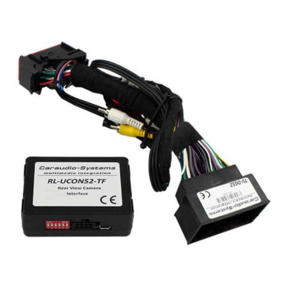
27-321
(RL-UCON52-TF)
Interface for activation of
factory rear-view camera input
compatible with Uconnect 5" or 8,4" system
with 52 pin connector
Video input to connect a rear-view camera
incl. video-in-motion
Legal Information
By law, watching moving pictures while driving is prohibited, the driver must not be
distracted. We do not accept any liability for material damage or personal injury resulting,
directly or indirectly, from installation or operation of this product. This product should
only be used while standing or to display fixed menus or rear-view-camera video when the
vehicle is moving, for example the MP3 menu for DVD upgrades.
Changes/updates of the vehicle's software can cause malfunctions of the interface.
Advertisement

Related Manuals for InCarTec r.LiNK-Interface 27-321


Summary of Contents for InCarTec r.LiNK-Interface 27-321
- Page 1 Website: www.incartec.co.uk E-Mail: sales@incartec.co.uk r.LiNK-Interface 27-321 (RL-UCON52-TF) Interface for activation of factory rear-view camera input compatible with Uconnect 5“ or 8,4“ system with 52 pin connector Video input to connect a rear-view camera incl. video-in-motion Legal Information By law, watching moving pictures while driving is prohibited, the driver must not be distracted.
-
Page 2: Table Of Contents
Contents 1. Prior to installation 1.1. Delivery contents 1.2. Check compatibility of vehicle and accessories 1.3. Connection schematic 1.4. Setting the Dip-switches of the CAN-box 2. Installation 2.1. Connecting CAN-Box, harness and factory navigation unit 2.2. Connections to rear-view camera 3. -
Page 3: Check Compatibility Of Vehicle And Accessories
1.2. Check compatibility of vehicle and accessories Requirements Vehicle Chrysler, Dodge, Fiat, Jeep, Lancia Navigation Uconnect 5” / 8,4” display with 52 pin connector Limitations Video-sources Only compatible to NTSC-video-sources 1.3. Connection schematic Rear-view camera Rear of monitor CAN-Box ZLC-TV506 +12V rear-view camera (max. -
Page 4: Setting The Dip-Switches Of The Can-Box
1.4. Setting the Dip-switches of the Can-box Vehicle/ navigation Dip 1 Dip 2 Dip 3 Dip 4 Dip 5 Dip 6 Video-in-motion permanent Video-in-motion selective* * With dip1 to OFF the included green cable is used to activate the video-in-motion function. Note: Dip switch functions of the CAN-box Dip 1 –... -
Page 5: Installation
2. Installation Switch off ignition and disconnect the vehicle’s battery! If according to factory rules disconnecting the battery has to be avoided, it is usually sufficient to put the vehicle is sleep-mode. In case sleep-mode does not work, disconnect the battery with a resistor lead. -
Page 6: Connections To Rear-View Camera
2.2. Connections to rear-view camera Rear-view camera +12V camera power (max. 500mA) Harness TV-DG52 Connect the video RCA of the rear-view camera to the female RCA connector of the harness TV-DG52. Connect the white cable of harness TV-DG52 to the camera power supply (+12V max 500mA). -
Page 7: Activation Of The Video-In-Motion Function
5. Activation of the video-in-motion function The video-in-motion can be activated and deactivated by Dip 1 or alternatively by the included loose green cable in connection with a switch (not included in delivery). Video-in-motion permanent With dip1 to ON the video-in-motion function is activated permanently without disturbing the navigation performance.