Advertisement
Quick Links
Advertisement

Related Manuals for MUSCLE D Megatron MT-CG


Summary of Contents for MUSCLE D Megatron MT-CG
- Page 1 Megatron Corner Gym MT-CG Installtion Manual www.muscledfit.com...
- Page 2 Table of Contents 01/ Safety Instructions 02/ Installation Steps Diagram and Checklist 03/ Product Description 04/ Product Parameters 05/ Maintenance Guide...
-
Page 3: 01/ Safety Instructions
01/ Safety Instructions: Thank you for choosing our company’s product. Proper use of the training equipment ensures your safety and convenience. Before using the training equipment, please read the following carefully: 1. Before using this product, please carefully read all the instructions and strictly follow the meth- ods described in the manual. -
Page 4: 02/ Installation Steps Diagram And Checklist
02/ Installation Steps Diagram and Checklist STEP 1: Main Frame Assembly Note: Note that MOST of the nuts, bolts and washers are already in place. Be sure to bolt the guide rods to the underside of the U-shaped base frame BEFORE loading the weight plates onto the guide rods. - Page 5 STEP 2: Seat Assembly Note that there is a pneumatic gas piston in the chrome seat post that assist the user adjusting the height of the seat pad. Make sure to follow the order of assembly for the nuts, bolts, and washers when replacing them into the respective holes. Installation checklist for this step Flat Washer Ø8...
- Page 6 Lat Pull Down Plate Assembly Most of the bolts, washers, and nuts are already in place. Tighten these on the Lat Pulldown Plate snugly and pay attention to the order of assembly. Attach Muscle D logo(42) to right side of Lat plate using bolts(34).
- Page 7 STEP 4: Pressing/Rowing Arm and Pulley Plate Assembly The most important part of this step is the securing of the axles on both sides of the pressing arm. Pay attention to the order of hardware assembly! Installation checklist for this step Spring Washer Ø8 Flat Washer...
- Page 8 STEP 5: Rotating Arms/Lat Pull Lap Rollers/Seat Pad Assembly The trickiest part is securing the axles on the end of the rotating arms and the attach- ment of the rotating arms to the brackets on the mainframe. Do these steps FIRST before the other steps so you will have room to work.
- Page 9 STEP 6: Main Cable Threading There are 4 cables…the one below is mainly for the Lat Pull/Rowing mechanism. Match the Letters on the cable(A-K) to the pulleys. This cable has a rounded black ball on one end and a threaded bolt on the other (goes into the selector stem. Note that some pulleys may have to be removed in order to thread the cables through the cable housings.
- Page 10 STEP 7: Ab Crunch Cable Threading There is a rounded black ball on one end that goes over pulley “A”. The other end has an eyelet that is bolted to the Mainframe directly below cable housing “C”. Start at the Ab Crunch (“A”) end of the cable as you may not have to remove any of the pulleys.
- Page 11 STEP 8: Suspended Double Pulley Housing Cable Threading There is a Threaded bolt on one end that attaches to the pulley housing (81)on the one end. The other end has carbiner clip that attaches to an eyelet on the bottom of the frame between the 2 pulleys.
- Page 12 STEP 9: Adjustable Crossover Pulley Arms Cable Threading This cable is long so pay attention to match the cable pathway to the pulleys (A-J). See the inset picture on the bottom left below as it shows how to take off the round- ed black ball on one end of the cable(67,68) so that you can thread it through most of the pulley housings…so that you do not have to remove the pulleys from most housings.
- Page 13 STEP 10: Attaching Weight Shrouds & Accessory Handles Attach metal weight stack shrouds (83,84) around the weight stack using the con- nector metal flat strap (85) to secure the 2 halves. Clip the Lat Pulldown Bar(87,90), Ab Crunch Harness(86,89) and 2 stirrup handles(80,88) to the respective ends of cables.
- Page 14 STEP 11: Attaching Hi/Lo Pulley/Leg Extension frame to main frame Attach the 2 L-shaped oval tubes (102,103) to the main frame on top and bottom. Then attach 102 tube to overhead 106 tube. The Oval vertical tube attached to the 106 tube at the top and to the 103 tube at the base.
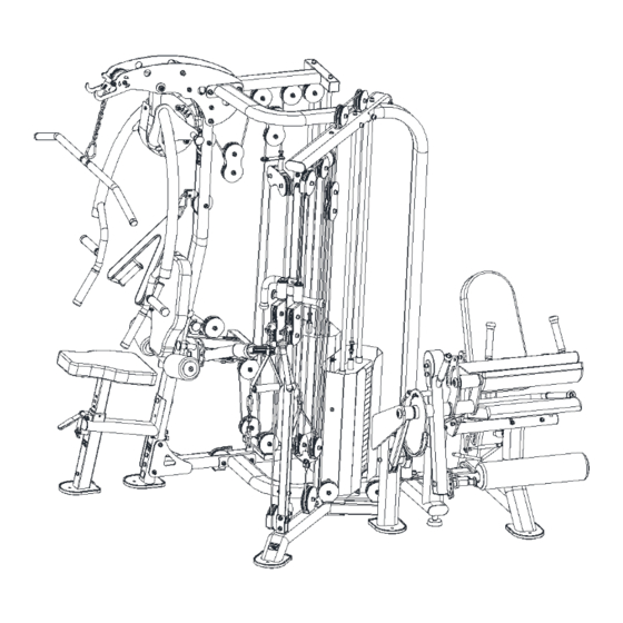
- Page 15 STEP 11: Installation completed image for reference.
- Page 16 STEP 12: Attaching Hi/Lo Pulley Carriage & Chrome Adjustment Tube Before attaching chrome adjustable height tube(108) to the frame, slide assembled adjustable carriage(109-111) onto the chrome tube with laser cut height numbers. Attach 2 pulley housings at the top and bottom of the chrome tube while attaching it to the top and bottom frames.
- Page 17 STEP 13: Attaching Leg Extension/Curl Seat and Cam support to the Frame Attach Seat support tubing(15) to the frame. Attach cam support structure(15) and cable redirection structure(13) to the frame. Installation checklist for this step Installation completed image for reference. Flat Washer Ø10 Hexagon Lock Nut...
- Page 18 STEP 14: Attaching Leg Curl Pad, Leg Extension/Curl Thigh pad, Cam, and Counterbalance Arm to Seat & Cam Structure Slide the steel axle(16) through Leg Extension/Curl arm(19),Cam (21), and Counter- balance Arm(22) through the metal hub with the bearings inside on the cam support structure.
- Page 19 STEP 15: Attaching Seat Support Tube, Seat Handles, Cam, and Seat Back Adjustment Lever First attached the seat support tube(36) to the frame. Attach seat back adjustment le- ver(34) to the underside of the seat structure using bolts & washers(2,3,25). Attach seat handles(35) to seat support structure using bolts, washers, and nuts(27,7,8).
- Page 20 STEP 16: Attaching Seat Back Support Tube, Seat Handles, Cam, and Seat Back Adjustment Lever, Scissor Flat Strap, & Gas Piston to Seat Frame First attach the seat back support tube(33) to the 4 flat strap metal pieces (31, 32) using 4 axles(23).
- Page 21 STEP 17: Attaching Short Cable to Hi/Lo Pulley/Leg Extension Frame First attach the cable(45) to the weight stack selector frame. Thread the cable thru the hole at the top of the oval tubing frame then up and over pulleys(A,B) down thru next hole in the frame, then under the top pulley(74) of the dual pulley housing(C).
- Page 22 STEP 18: Attaching the Pads, Roller, and Weight Shrouds. Attach metal weight stack shrouds (83,84) around the weight stack using the connec- tor metal flat strap (85) to secure the 2 halves. Attach seat pad & back(39,40),thigh pad(38),and leg roller(43) using hardware shown. Installation checklist for this step Spring Washer Ø8...
- Page 23 STEP 19: Threading Leg Extension/Leg Curl Cable Start with the end of the cable(48) that has the metal clasp/eyelet(46)on the end and bolt the cable to the bottom of dual pulleys(49). Thread cable thru Pulley(F)then up and over the bottom pulley(E)then down and under pulleys(D & E). Cable then goes top of pulley(B)and under pulley(A).
- Page 24 STEP 20: Threading Adjustable Height Hi/Low Pulley Cable. Take off the rounded plastic end of the cable(50) removing bolts and nut (67,68). Slide cable out of plastic then remove the inner metal retainer thru the open slot on the side of the retainer. This will allow the cable to pass thru all pulley housings without having to remove pulleys.
- Page 25 Installation completed image for reference. (BACK)
- Page 26 Installation completed image for reference. (FRONT)
-
Page 27: 05/ Maintenance Guide
03/ Product Description This machine is indoor fitness equipment suitable for aerobic cardiovascular exercise. Its primary purpose is to increase cardiovascular function, with muscle training as a secondary aspect. It targets various muscle groups such as the chest muscles, aiming to achieve strength and bodybuilding goals.
Need help?
Do you have a question about the Megatron MT-CG and is the answer not in the manual?
Questions and answers