Table of Contents
Advertisement
Quick Links
Advertisement
Table of Contents

Subscribe to Our Youtube Channel
Related Manuals for VAN DER ENDE ZN045 AC ZAplus


Summary of Contents for VAN DER ENDE ZN045 AC ZAplus
- Page 1 MANUAL Enfan Horizontal circulation Version: 2024-04 Page 1 of 32...
-
Page 2: Foreword
FOREWORD This user manual is intended for users of these fans and technicians who install and maintain them. The manual and operating instructions are bundled together in a single document. Each chapter is numbered and, where necessary, divided into sections. The table of contents on page 3 contains an overview of the chapters and paragraphs, with references to page numbers. -
Page 3: Table Of Contents
CONTENTS Foreword ............................2 Contents ............................3 Identification .......................... 4 General .......................... 4 1.1.1 Description of the device ..................... 4 1.1.2 Specifications ......................4 1.1.3 Diagram of the system ....................5 Users ..........................6 Use ..........................6 Authorized servicers ......................6 Operating environment .................... -
Page 4: Identification
IDENTIFICATION This overview contains general information about the device. The purpose of this part is to indicate the limits and overall operation of the device, and the areas it is used in. 1.1 General 1.1.1 Description of the device The Enfan consists of a fan mounted vertically on a lattice shelf using mounting brackets and mounting brackets. -
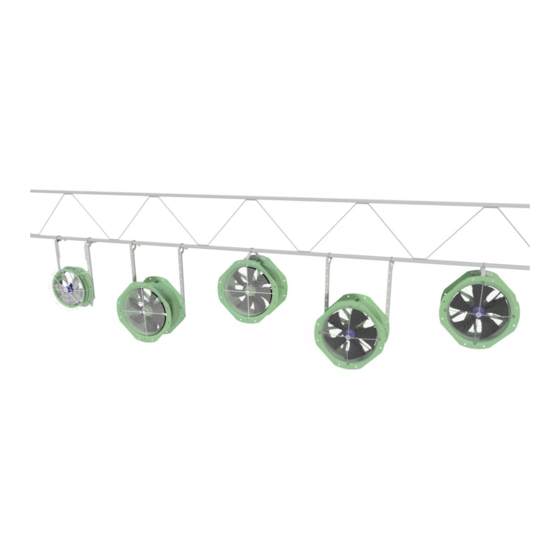
Page 5: Diagram Of The System
1.1.3 Diagram of the system In the picture below there is a schematic view of the most important components of the system with the various types of fans. Figure 1 Diagram of the Enfan The long and short mounting brackets can be used on either the ZN045 as the ZG045 fan. Only long mounting brackets can be used for the FG035 fan. -
Page 6: Users
It should not be possible for people to reach the fan without any tools. The Enfan is not designed for use in any other environment than that described above, except for customer-specific requests under the guidance of Van der Ende. The Enfan is not suitable for use in explosive environments. -
Page 7: Description
DESCRIPTION 2.1 General The purpose and function of the Enfan is to create a horizontal air movement in greenhouses. External influences create a natural draft in the greenhouse, which causes a temperature difference. In addition, a difference in humidity can also arise in the greenhouse due to this natural draft. By setting the air in the greenhouse in motion with the Enfan fans, a more equal distribution of temperature and humidity is created, which minimizes the differences over the greenhouse. -
Page 8: Safety Instructions
SAFETY INSTRUCTIONS When working on the Enfan, always make sure the plug is disconnected from the power supply! This prevents the fan starting unexpectedly or unintentionally. Only use self-locking nuts to mount the Enfan. Failure to do so may result in parts vibrating loose and falling off. -
Page 9: Installation
INSTALLATION This chapter describes the installation of the Enfan. The separate parts must first be assembled into a single unit, ready for suspension. The Enfan can be attached using either short mounting brackets or long mounting brackets. An overview is attached to help you. 4.1 Enfan parts Quantity Description... - Page 10 Options Set outflow grid for Enfan ZN045 + ZG045 1x outflow grid for ZN045 + ZG045 4x torx screws Set inflow grid for Enfan ZN045 1x inflow grid for ZN045 4x torx screws Set inflow grid for Enfan ZG045 1x inflow grid for ZG045 4x torx screws Set outflow guide flap, applicable on: 1x mounting bracket Enfan/Airmix...
-
Page 11: How To Suspend The Enfan Using Long Mounting Brackets
4.2 How to suspend the Enfan using long mounting brackets 4.2.1 Mount bracket on lattice shelf • Attach the two mounting brackets (7) to the lattice shelf (1); Use two M8 rivet (4), four M8 standard washers or fender washers (2) and four M8 self-locking nuts (3);... -
Page 12: Attach Fan To Bracket
4.2.3 Attach fan to bracket • Attach the fan (5) to the mounting brackets (4); Use four M8 x 20 bolts (1), eight M8 fender washers (2) and four M8 self-locking nuts (5); ▪ See Figure 3; When there is an inflow or outflow grid applied at the ZN045 fan, there will be delivered torx screws with it. -
Page 13: Mounting Instructions For The Enfan Using Short Mounting Brackets
4.3 Mounting instructions for the Enfan using short mounting brackets 4.3.1 Attachment bracket to the lattice • Attach the mounting bracket (3) to the lattice (2); Use a rivet M8 (1), two M8 fender washers (4) and two M8 self-locking nuts (5); ▪... -
Page 14: Mounting Instructions For The Fg035 Fan
4.4 Mounting instructions for the FG035 fan The mounting brackets for the FG035 fan are special developed to attach this fan to the lattice. This special developed mounting brackets fix the fan and optionally outflow grid. With the help of these mounting brackets it’s possible to mount the fan on three different heights. -
Page 15: Attaching The Brackets To The Fan
4.4.2 Attaching the brackets to the fan The numbering from Figure 6 is used for mounting the FG035 fan to the mounting brackets and the outflow grid. • Attach the fan (1) to the mounting brackets (3) with the optionally outflow grid (2); Use four M8 x 20 bolts(4), eight M8 washers (6) and four M8 self-locking nuts (5) for the attachment of the fan (1) to the mounting brackets (3);... - Page 16 Figure 7: Mounting of the FG035 fan and outflow grid to the mounting brackets Page 16 of 32...
-
Page 17: Air Flow Guide Plates
4.5 Air flow guide plates Air flow guide plates direct the air that is blown from the ventilator. Various configurations are possible to control the air flow. The configurations presented in chapter 4.5.1 are tested by VDEG on their desired effect. -
Page 18: Assembling The Air Flow Guide Plates
4.5.2 Assembling the air flow guide plates To attach the guide plates to the Enfan, the mounting bracket must first be attached to the fan. One can also choose to attach the guide plates to the mounting bracket before connecting the bracket to the Enfan. Requirements: •... - Page 19 If two guide plates are used to guide the air flow, Figure 12 shows how they are connected to the mounting bracket. Requirements for mounting one flow guide plate: • 2x Air flow guide plate • 4x hexagonal tap bolt m5 x 16 •...
-
Page 20: Connecting Thermostatic Switch (50 Hz 230-400 Vac)
5 CONNECTING THERMOSTATIC SWITCH (50 HZ 230–400 VAC) A thermostatic switch is built in to the winding of every fan as standard. When connected, this switch turns the motor off if voltage levels are exceeded and the internal temperature rises above 100 °C. The motor gets too hot if the fan becomes blocked, or similar. -
Page 21: Operation/Using For The First Time
OPERATION/USING FOR THE FIRST TIME Operating the Enfan is simple: if it is connected to the power supply it will start ventilating, if it is disconnected it will stop ventilating. It is possible to set the speed by adjusting the voltage at the plug with something like a control transformer or inverter. -
Page 22: Connection Diagram Zn045 Ec-Fan 200-277 V Ac ~1 50/60 Hz
6.1.3 Connection diagram ZN045 EC-fan 200-277 V AC ~1 50/60 Hz Figure 17: Connecting diagram ZN045-6IL The power cable for the ZN045 is an 1-phase cable. This power cable must be connected to the following terminals inside the terminal box of the fan (see Figure 17): −... -
Page 23: Connection Diagram Zg045 And Fg035
6.1.4 Connection diagram ZG045 and FG035 Figure 18 (left) Connecting diagram ZG045 and FG035 Figure 19 (right) Connecting feedback circuit in the ZG045 and FG035 The power cable for the ZG045 and the FG035 is an 1-phase cable. This power cable must be connected to the following terminals inside the terminal box of the fan (see Figure 18): −... -
Page 24: Maintenance
MAINTENANCE When servicing the Enfan, the plug must be removed from the socket to prevent unexpected and unwanted starting. The Enfan requires little maintenance in terms of maintenance. What should be observed at all times Keep the suction side of the fan free of foreign objects and contaminants. Replace the capacitor after 10,000 operating hours. -
Page 25: Ce Declaration Of Conformity
CE DECLARATION OF CONFORMITY EC DECLARATION OF CONFORMITY (In accordance with Annex IIA of the Machinery Directive 2006/42/EC) Van der Ende Pompen Aartsdijkweg 23 2676 LE Maasdijk Nederland declare, under sole responsibility, that the following machine; ® Enfan to which this declaration relates is in conformity with the following directives;... -
Page 26: Ukca Declaration Of Conformity
UKCA DECLARATION OF CONFORMITY UKCA DECLARATION OF CONFORMITY Van der Ende Pompen Aartsdijkweg 23 2676 LE Maasdijk Nederland declare, under sole responsibility, that the following machine; ® Enfan to which this declaration relates is in conformity with the following directives;... -
Page 27: Attachments
ATTACHMENTS • Enfan mounting brackets • CE declaration concerning fan • UKCA declaration concerning fan Page 27 of 32... -
Page 28: Enfan Mounting Brackets
Enfan mounting brackets Page 28 of 32... -
Page 29: Ce Declaration Concerning The Fan
CE declaration concerning the fan Page 29 of 32... -
Page 30: Ukca Declaration Concerning The Fan
UKCA Declaration concerning the fan Page 30 of 32... - Page 31 Page 31 of 32...
- Page 32 Aartsdijkweg 23, 2676 LE Maasdijk, The Netherlands +31 174 51 50 50 · info@vanderendegroup.com · www.vanderendegroup.com Page 32 of 32...
Need help?
Do you have a question about the ZN045 AC ZAplus and is the answer not in the manual?
Questions and answers