
Related Manuals for Monoprice 44519


Summary of Contents for Monoprice 44519
- Page 1 Monoprice 4-Zone Home Audio ™ MULTIZONE CONTROLLER AND AMPLIFIER KIT 44519 User Manual...
-
Page 2: Safety Warnings And Guidelines
SAFETY WARNINGS AND GUIDELINES Please read this entire manual before using the Monoprice Multizone Controller & Amplifier Kit, paying ™ extra attention to these safety warnings and guidelines. Please keep this manual in a safe place for future reference. This Home Audio Kit is intended for indoor use only. -
Page 3: Table Of Contents
TABLE OF CONTENTS SAFETY WARNINGS AND GUIDELINES ..................................... 2 INTRODUCTION ..............................................4 FEATURES ..................................................4 PACKAGE CONTENTS ............................................4 PRODUCT OVERVIEW ............................................5 FRONT PANEL..............................................5 REAR PANEL ..............................................5 KEYPAD CONTROLLERS .......................................... 7 IR REMOTE CONTROL ..........................................8 LOCATION PLANNING ............................................. 8 CABLE PREPARATION ............................................ -
Page 4: Introduction
Take an inventory of the package contents to make sure you have all the items listed below. Please contact Monoprice Customer Service for a replacement if anything is missing or damaged. 1x 6 x 4 Multizone Home Audio Controller / Amplifier •... -
Page 5: Product Overview
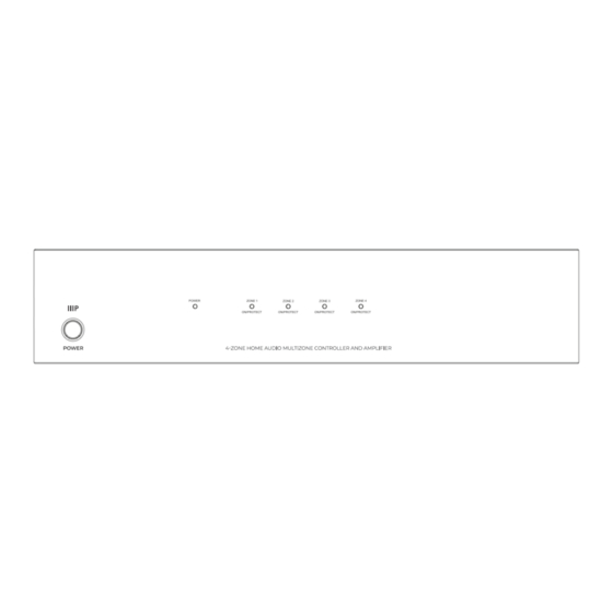
PRODUCT OVERVIEW FRONT PANEL Power Button — press the power button to turn the controller/amplifier on or off. NOTE: When the controller is powered on, each zone will remain on standby until its keypad is activated. 2. Power Led Indicator — this LED indicator is off when the controller is powered off and will illuminate red when there is power. - Page 6 17. Expansion Input and Output — these two ribbon cable connectors are used to connect to up to two additional 6 x 4 (44519) or 6 x 6 (10761) controllers to create up to 16 distinct zones. Use the included ribbon cable to connect the output of one controller to the input of the second. A third controller can then be connected to the output of the second.
-
Page 7: Keypad Controllers
KEYPAD CONTROLLERS 24. LED Display — the digital LED display shows the number of the source device, as well as the volume, treble, and bass levels. Numeric LED 25. Vol. LED — when illuminated, this LED indicates that the is displaying the volume Down level. -
Page 8: Ir Remote Control
IR REMOTE CONTROL 36. IR Emitter — when using the remote control, the IR emitter should be pointed at the IR receiver on the Keypad Controller. 37. Mute Button — press this button to mute/unmute the zone. 38. Power Button — press this button to power the zone on/off. 39. -
Page 9: Cable Preparation
CABLE PREPARATION You will need a variety of cables for this installation, the specifics of which depend on your installation choices. None of the cables or connectors mentioned in this section are included in the system. Note: If you plan on running any of these cables through the walls, through a connecting floor, or inside an air duct in commercial applications, they should be rated for In-Wall, Riser (between floors), or Plenum (air duct) use, respectively. -
Page 10: Rca Cables
Whatever speaker wire you get, make sure that it has marks to distinguish one conductor from another. Most speaker wires use a colored stripe to identify one of the conductors. The identified conductor is usually used for the positive (+/red) connection and the other for the negative (-/black) side. NOTE: When cutting speaker wires, ensure that the length of each stereo pair is the same. -
Page 11: Rs232 Serial Cable
RS232 SERIAL CABLE If you will be using the RS232 external control option, you will need to have an RS232 serial cable to connect your PC to the Master Controller/Amplifier. The specific wiring needs of this cable are determined by your specific setup. You will need a male DB9 (DE9) plug on the end that connects to the RS232 Serial Control Master Controller/Amplifier. -
Page 12: Connecting The Wallplate Keypad Controllers
CONNECTING THE WALLPLATE KEYPAD CONTROLLERS Set the three DIP switches on each Keypad Controller to one of the four identification patterns listed below. Each Keypad Controller connected to the same Master Controller/Amplifier must have a unique identification. NOTE: The identification is localized to each Master Controller/Amplifier device. If multiple Master Controllers are in use, each one will have its own set of keypads with the same identification numbers as keypads on another Master Controller. -
Page 13: Connecting Analog Rca Source Devices
3. Carefully insert the positive and negative conductors on each speaker wire into the appropriate sockets in the Euroblock terminal. Tighten the screws on the terminal block until there is a good, solid mechanical and electrical connection. 4. Connect the other ends of each speaker wire to the positive and negative terminals on each of the two speakers. -
Page 14: Connecting Power
Each numbered IR emitter jack corresponds to a specific source device. When an IR remote control is used in a particular zone, the system determines which source device is selected for that zone and sends the IR signal out to that specific device's IR emitter. In addition to the specific IR signaling to individual source devices, the ALL jack repeats all IR signals received, regardless of the zone or the selected source device. -
Page 15: Rs232 Serial Control
RS232 SERIAL CONTROL All keypad and remote control operations can be performed by a computer connected to the Master Controller/Amplifier using an RS232 connection. The communications standard uses: Baud Rate: 9600, 8, N, 1 DB9 Connector Pinout Tx, Rx, GND 'CR': Carriage Return (0x0D) No case capitalization/lowercase Control order structure <xxPPuu'CR' Reply control order frame>... - Page 16 Reply command: > xxaabbccddeeffgghhiijj'CR' aa: PA control status bb: Power control status ([5]: Backup Zone Power Status only on zone) cc: Mute control status dd: DT control status ee: Volume control status ff: Treble control status gg: Bass control status hh: Balance control status ii: Source control status jj: keypad connecting status...
-
Page 17: Technical Specifications
gg: Bass control status hh: Balance control status ii: Source control status jj: keypad connect status (00: disconnect 01: connected) Inquiry command structure (2) ?xxPP'CR' xx: stands for control object code 10: All Zone of Main Unit 1. 20: All Zone of Main Unit 2. 30: All Zone of Main Unit 3. -
Page 18: Customer Service
If you have any problems with your order, please allow us to make it right. You can contact a Monoprice Customer Service representative through the Live Chat link on our website www.monoprice.com or via email at support@monoprice.com. Check the website for support times and links. -
Page 19: Regulatory Compliance
(1) this device may not cause harmful interference, and (2) this device must accept any interference received, including interference that may cause undesired operation. Modifying the equipment without Monoprice's authorization may result in the equipment no longer complying with FCC requirements for Class B digital devices. In that event, your right to use the equipment may be limited by FCC regulations, and you may be required to correct any interference to radio or television communications at your own expense. - Page 20 Product pictures are for reference only. Brea, CA 92821 – USA Specifications described herein are subject to change without prior notification. www.monoprice.com ™ Monoprice and all Monoprice logos are trademarks of Monoprice Inc. Copyright © 2024 Monoprice, Inc. All rights reserved.
Need help?
Do you have a question about the 44519 and is the answer not in the manual?
Questions and answers