Bose EdgeMax EM90 Service Manual
Hide thumbs
Also See for EdgeMax EM90:
- Installation manual (37 pages) ,
- Design manual (22 pages) ,
- Installation manual (88 pages)

Related Manuals for Bose EdgeMax EM90


Summary of Contents for Bose EdgeMax EM90
- Page 1 Bose EdgeMax ® EM90 and EM180 Loudspeaker ©2017 Bose Corporation Service Manual Reference Number 778844-SM Rev.01...
-
Page 2: Table Of Contents
BOSE CORPORATION WHICH IS BEING FURNISHED ONLY FOR THE PURPOSE OF SERVICING THE IDENTIFIED BOSE PRODUCT BY AN AUTHORIZED BOSE SERVICE CENTER AND SHALL NOT BE REPRODUCED OR USED FOR ANY OTHER PURPOSE. WARRANTY The Bose EdgeMax Loud Speaker is covered by a limited 5-year warranty. -
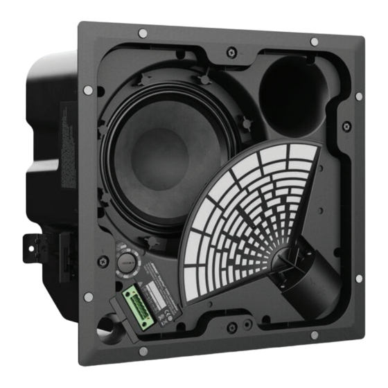
Page 3: Product Description
EdgeMax in-ceiling premium loudspeakers are available with two different horizontal coverage patterns. EdgeMax EM90 models provide nominal 90-degree horizontal coverage and are intended for in-ceiling mounting near room corners. EdgeMax EM180 models provide nominal 180-degree horizontal coverage and are intended for in-ceiling mounting near wall boundaries centered along target coverage zones. -
Page 4: Specifications
2. This part is referenced for informational purposes only. It is not stocked as a repair part. Refer to the next higher assembly for a replacement part. This part is critical for safety purposes. Failure to use a Bose recommended part may result in a safety hazard and may void the regulatory certification. -
Page 5: Packaging Parts List
Packaging Parts List Em90 and Em180 Loudspeaker Item Number Description Part Number Qty. Note CUSHION, EPE, PG90/180 CARTON 799319-001S GUIDE, INSTALL, EM90/EM180LDSPKR 792495-0010 SHIELD, PAINT, SVCE 788635-001S TEMPLATE, CUT-OUT, CRDBRD, B FLUTE, SVCE 789385-001S KIT, GRILLE, WHITE, SVCE 788330-021S KIT, GRILLE, ARTIC WHITE, SVCE 788330-022S END CAP, PACKAGING, TOP 797588-001S... -
Page 6: Main Assembly Parts List
Main Assembly Part List EM90 and EM180 Loudspeaker Item Number Description Part Number Qty. Note NUT, 10-24, ACORN 787928-0110 SCREW, ANCHOR 777181-0110 PCB ASSY, CROSSOVER, 90 783116-001S PCB ASSY, CROSSOVER, 180 786219-001S WOOFER, 8IN 778402-001S ASSY, TRANSFORMER/SWITCH, 80 WATT 781821-001S DRIVER, COMPRESSION, FERRITE, 1 IN 778675-001S GASKET, ENCLOSURE, SEAL... -
Page 7: Schematic And Connector Diagrams
Schematic Diagrams EM90 and EM180 Loudspeakers EM90 Crossover Figure 3 EM180 Crossover Figure 4... - Page 8 Connector Diagrams O UT 70V/100V 8 Ohm 2.5W* 8Ω NC** 100V Figure 5...
-
Page 9: Disassembly Procedures
Disassembly Procedure 1. Grille Removal 1.2 Remove the magnetically mounted grille from the Edgemax assembly by lifting on the edges. Figure 6. Note: A lanyard is attached to the grille and a brush clip is attached at the opposite end. Removal of the brush clip will be necessary to place the grille off to the side, as shown in fi... - Page 10 Disassembly Procedure 2.3 The four red arrows shown in fi gure 9, reference the four anchor bolts that secure the baffl e to the enclosure. The anchor bolts must be loosened to separate the baffl e from the enclosure. Figure 9 2.4 Figure 10 shows one of the four anchor bolt 5/16 head and washer and fi...
-
Page 11: Driver Removal
Disassembly Procedure Carefully lift off the baffl e from the enclo- sure, taking care not to damage the baffl e or internal components as shown in fi gure 13. Figure 13 3. Driver Removal 3.1 Refer to the disassembly procedures, see above. -
Page 12: Driver Flange Removal
Disassembly Procedure 3.4 Remove the four screws indicated by the red arrows as shown in fi gure 17. The driver and driver fl ange will come off as an assembly. Note: During remounting of the driver fl ange to the baffl e, do not tighten the six screws until all are threaded in position, then tighten, as there is a possibility of cross threading one of the screws. -
Page 13: Woofer Removal
Disassembly Procedure 5.3 Remove the input connector from the crossover as indicated by the red arrow in Figure 21. Figure 21 Note: The crossover can be placed off to the side as shown in fi gure 22. Figure 22 6. Woofer Removal 6.1 Perform procedure 5 to remove the crossover. -
Page 14: Transformer And Switch Assembly
Disassembly Procedure 7. Transformer and Switch Assembly Removal 7.1 Refer to procedures 1 and 2. 7.2 Remove the four T20 Torx screws securing the metal plate to the baffl e assembly as shown by red arrows in fi gure Figure 25 7.3 After removing the four screws, carefully lift out the transformer and it place off to the side as shown in fi... - Page 15 Disassembly Procedure 7.6 Remove the one half inch nut to remove the switch from the baffl e as indicated by the red arrow, shown in fi gure 29. Figure 29 7.7 Figure 30, Lift out the switch. Figure 30 7.8 Figure 31 shows the 6 pin female connector barrier strip, this is not a serviceable part.
-
Page 16: Enclosure And Baffl E Gaskets
Enclosure and Baffl e Gasket 8. Enclosure Gasket 8.1 The enclosure and the baffl e have gaskets to prevent air leaks. The enclosure gasket is glued as indicated by red arrows in fi gure 33. The green arrows indicate the non glued baffl... -
Page 17: Test Procedures
Test Procedures 3. Rub and Tick Test EM90 and EM180 Test Procedures Equipment Required: 3.1 Apply a 10 Hz, 10Vrms, + 1 Vrms signal • Audio signal generator to the 8 ohm input. • Male, 6 pin plug, Dinkle, PT: 792047-001S •... -
Page 18: Service Manual Revision History
REVISION HISTORY DATE DESCRIPTION PAGES AFFECTED 10/2017 INITIAL RELEASE 11/2019 Added Arctic White Grille... - Page 19 Bose Corporation The Mountain Framingham Massachusetts USA 01701 P/N: 778844-SM REV 01, 11/2019 (P) http://serviceops.bose.com...
Need help?
Do you have a question about the EdgeMax EM90 and is the answer not in the manual?
Questions and answers