
Related Manuals for CMC S19N


Summary of Contents for CMC S19N
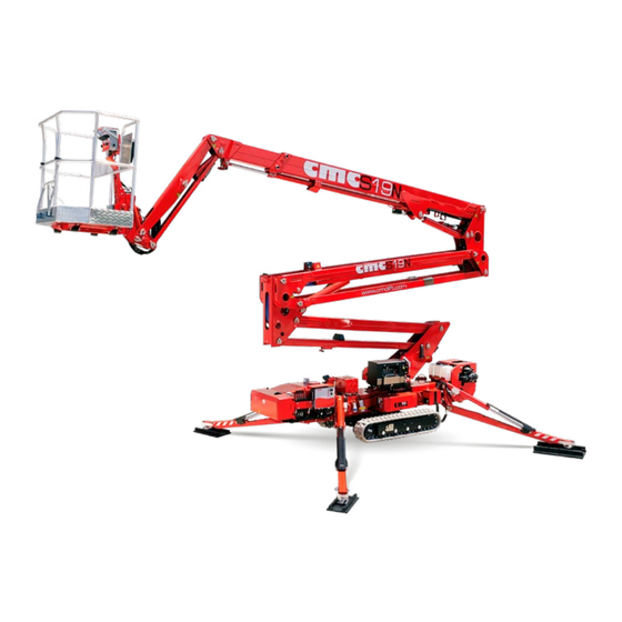
- Page 1 USE AND MAINTENANCE MANUAL Man.219 Rev.8 S19N Mobile Elevating Work Platform(MEWP)
-
Page 3: Content Of The Manual
➔ This manual is addressed to: ▪ users: operators, ground assistants, guard staff, safety man- ager, service manager; manufacturers, dealers, owners, lessors or lessee, brokers. ▪ MAN.219 Rev.8 ENG - Use and maintenance manual S19N page... -
Page 4: Where And How To Keep The Manual
ANSI/SAIA A92.20-2020 ANSI/SAIA A92.24-2018 IEC 60529 invalidates the warranty. ANSI/SAIA A92.22-2020 ANSI Z359.1 EN 62061 CAN/CSA B354.6 (2017) CAN/CSA B354.7 (2017) ISO 13857 AS NZS 1418.10- AS/NZS 1418.10-2011 ISO 20381 2011_A1-2017 MAN.219 Rev.8 ENG - Use and maintenance manual S19N page... - Page 5 Year 2021 and on their manuals. C.M.C. s.r.l. MAN.219 Rev.8 ENG - Use and maintenance manual S19N page...
-
Page 6: Specifications
0.72 ft in transport configuration Max. height to stabilize 0,45 m 1.48 ft on obstacle Tracks (l x h) 1,45x0,18x0,30 m 4.76x0.59x0,98 ft Width tracks adjustment 0,78/1,08 m 2.56/3.54 ft (*optional) MAN.219 Rev.8 ENG - Use and maintenance manual S19N page... - Page 7 Max allowed rotation speed 0,7 m/s (2.3 ft/s) Max allowed manual force in the basket with 1 op- 400 N erator Tightening torque Bolts of the bearing M16 cl 10.9 28 daNm MAN.219 Rev.8 ENG - Use and maintenance manual S19N page...
-
Page 8: Identification Plate
Identification plate On the MEWP turret, there is a plate with all the identification data of the machine: Picture 1: identification plate. MAN.219 Rev.8 ENG - Use and maintenance manual S19N page... -
Page 9: Tüv Certification
MEWP in its transport configuration or in the stowed position (EN 280 par. 1.4 - ANSI/SAIA A92.20 par. 3). Loading cycle: cycle starts from the access position, continues performing the work and finishes returning to the access position. MAN.219 Rev.8 ENG - Use and maintenance manual S19N page... -
Page 10: Working Diagram
Working diagram Picture 2: working diagram. MAN.219 Rev.8 ENG - Use and maintenance manual S19N page... -
Page 11: Description Of The Main Components
Definition The machine is called S19N and it is a mobile elevating work platform (MEWP): • machine/device intended for moving persons, tools and material to working positions, consisting of at least a work platform with con- trols, an extending structure and a chassis (ANSI/SAIA 92.20 par. - Page 12 9 10 (Picture 3). The extraction movement (or return) of the telescopic boom is obtained by moving the "telescopic boom extraction cylinder" 11 (Picture 3). MAN.219 Rev.8 ENG - Use and maintenance manual S19N page...
-
Page 13: Control Stations
Also in this case, on the left side of the electric box there is the platform Yanmar), with an auxiliary 110/120/230 V electric motor or in a 48 V elec- fuse board. tric version powered by 100 Ah lithium battery pack. MAN.219 Rev.8 ENG - Use and maintenance manual S19N page... - Page 14 • the hourmeter. On the left side of the electric box, there is the platform fuse board. MAN.219 Rev.8 ENG - Use and maintenance manual S19N page...
- Page 15 Picture 4d: power supply selector (*optional). By opening the cover of the emergency control station, the basket control station is disabled. Basket po- Electric motor’s wer supply power supply Picture 4e: dual power sockets (*optional). MAN.219 Rev.8 ENG - Use and maintenance manual S19N page...
- Page 16 80% of the maximum allowed; • moment limiter lock warning 5 (Picture 5): this red light turns on when the outreach reaches the maximum threshold; MAN.219 Rev.8 ENG - Use and maintenance manual S19N page...
- Page 17 - pushing the lever backward, the stabilizer withdraws. o left front stabilizer lever 3 (Picture 7) - pushing the lever forward, the stabilizer lowers. - pushing the lever backwards, the stabilizer withdraws. MAN.219 Rev.8 ENG - Use and maintenance manual S19N page...
- Page 18 J2 (Picture 8) - pushing it upward, the left crawler goes forward; - pushing it downward, the left crawler goes backward; Picture 9: left and right side of the wired remote control. MAN.219 Rev.8 ENG - Use and maintenance manual S19N page...
- Page 19 10 (Picture 10): during the opera- tion. tions to close the S19N, if the machine stops, it’s possible to re- start the operations pushing this yellow button with the manoeu- hen you choose to use the emergency control station, you vres.
-
Page 20: Use Procedures
9 (Picture 11): this red light, if 12,5 m/s (45 Km/h). We hereby enclose the Beaufort wind scale (Table 1): switched on, shows the consent to stabilize the machine; MAN.219 Rev.8 ENG - Use and maintenance manual S19N page... -
Page 21: Safety Distances
We recommend the use of an anemometer, to determine direction and speed of wind. Any addition that increases the wind load on the MEWP, such as warning signs, is prohibited. MAN.219 Rev.8 ENG - Use and maintenance manual S19N page... - Page 22 Comply with the rules in force about width, height, weight and transport speed allowed. Check that the limit gauge is compatible with the features of the route to be made (i.e. galleries, bridges, electrical and phone lines, etc.). MAN.219 Rev.8 ENG - Use and maintenance manual S19N page...
- Page 23 5. Control the travel operations slowly and only in the direction showed in the figure below, by the wired remote control: the bas- ket, if not disassembled, shall always be placed at the rear of the machine. MAN.219 Rev.8 ENG - Use and maintenance manual S19N page...
- Page 24 3. Make sure the soil bears the load of the outriggers and check that there are no manholes, floors or other soft structures in the contact point of every outriggers plate with the ground. MAN.219 Rev.8 ENG - Use and maintenance manual S19N page...
- Page 25 11. Once the basket is coupled, insert the cotter pin P and the forelock C (Picture 16). It is essential to carry out the stabilization operations by oper- ating on all four levers simultaneously. Once the feet will all have MAN.219 Rev.8 ENG - Use and maintenance manual S19N page...
- Page 26 When the maximum allowable outreach is reached (see the working dia- since it could cause heavy damages to the carpentry. gram in Picture 2), the alarm indicator 5 lights up (Picture 5). MAN.219 Rev.8 ENG - Use and maintenance manual S19N page...
- Page 27 20. Then destabilize the MEWP, performing the withdrawal of the out- aerial part (pantograph, boom, jib) to have accidental impacts with these riggers by the proper levers 1, 2, 3, 4 (Picture 7). MAN.219 Rev.8 ENG - Use and maintenance manual S19N page...
-
Page 28: Emergency Operations
AT THE END OF EACH WORKING SESSION AND HOWEVER AT LEAST EVERY 15 DAYS, IF THE MEWP IS NOT USED, ABSOLUTELY RECHARGE THE BATTERY PACK. MAN.219 Rev.8 ENG - Use and maintenance manual S19N page... - Page 29 Bring the manual pump handle supplied on the chassis and insert it in the proper point of pumping (Picture 17), near the emergen- cy control station. MAN.219 Rev.8 ENG - Use and maintenance manual S19N page...
- Page 30 (Picture 21) under the proportional lever on the emergency control station, so that the same lever stays com- Picture 19: tap selector for platform/stabilizers electrovalves. pletely lifted and blocked. MAN.219 Rev.8 ENG - Use and maintenance manual S19N page...
- Page 31 5 if they are enlargeable as *optional). It is advisable to alternate two lowering cycles of the front out- riggers with two of the rear ones. MAN.219 Rev.8 ENG - Use and maintenance manual S19N page...
- Page 32 It can be activated by: o red activation button (Picture 24) on the left side of the basket control station; o sealed activation lever (Picture 24) at the bottom of the turret box. MAN.219 Rev.8 ENG - Use and maintenance manual S19N page...
-
Page 33: Safety Rules
– by the operators; user – of the liabilities coming from an incorrect functioning of the safety devices. Do not use the MEWP under drug or alcohol effect; MAN.219 Rev.8 ENG - Use and maintenance manual S19N page... - Page 34 Before restarting the machine, check that the ➔ Check that nobody is within the MEWP action range. dangerous conditions are over; ➔ Stabilize the truck through the outriggers. MAN.219 Rev.8 ENG - Use and maintenance manual S19N page...
- Page 35 It is forbidden to use ladders or tables on the basket in order to in- crease the MEWP outreach or working height; Do not throw objects (tools) upside down or vice versa. MAN.219 Rev.8 ENG - Use and maintenance manual S19N page...
-
Page 36: Safety Devices
▪ Limit switch boom lifting-lowering in parking position. A - Electrical devices ▪ Removable key for the MEWP engine ignition. ▪ Emergency stop buttons on control stations. ▪ Emergency stop buttons on the control stations. MAN.219 Rev.8 ENG - Use and maintenance manual S19N page... - Page 37 Before using the MEWP, it is compulsory to check the presence and the perfect readability of these marks. In case of absence or decay of the marks, contact the Service. Picture 25: identification plate (fac-simile). MAN.219 Rev.8 ENG - Use and maintenance manual S19N page...
- Page 38 Picture 26: machine model label. Picture 27: maximum capacity in the basket. Picture 28: working diagram. MAN.219 Rev.8 ENG - Use and maintenance manual S19N page...
- Page 39 Picture 29: wired remote control. Picture 32: stabilizers controls. Picture 30: left and right side of wired remote control. Picture 31: error code display. Picture 33: Honda chassis box. MAN.219 Rev.8 ENG - Use and maintenance manual S19N page...
- Page 40 Picture 34: Kubota* chassis box. Picture 36: basket control station. Picture 37: platform (emergency) control station. Picture 35: chassis box in full lithium* version. MAN.219 Rev.8 ENG - Use and maintenance manual S19N page...
- Page 41 Picture 44: maximum slopes for travel. Picture 40: indication of air/water supplies. Picture 45: use and maintenance manual box. Picture 41: indication of 12 V socket. Picture 46: indication of maximum frame inclination. MAN.219 Rev.8 ENG - Use and maintenance manual S19N page...
- Page 42 Picture 48: prohibition to stand in work area. Picture 55: indication of basket levelling valves. Picture 49: prohibition to remove safety devices. Picture 56: auxiliary electric engines (*optional). Picture 50: indication for fuel refill. MAN.219 Rev.8 ENG - Use and maintenance manual S19N page...
- Page 43 Picture 59: indication of frame coupling. Picture 60: indication of fork points. Picture 64: general obligations and prohibitions. Picture 61: warning for basket operator fainting. Picture 65: warning for tracks lifting during stabilization. MAN.219 Rev.8 ENG - Use and maintenance manual S19N page...
- Page 44 Picture 69: crushing and cutting hazard. Picture 74: prohibition to wet the machine. Picture 70: high pressure hazard. Picture 75: warning to refer to use and maintenance manual. Picture 71: danger of falling. MAN.219 Rev.8 ENG - Use and maintenance manual S19N page...
- Page 45 Picture 76: MEWP use guidelines. Picture 77: compliance with ANSI and CAN/CSA rules. Picture 78: inspection tag. MAN.219 Rev.8 ENG - Use and maintenance manual S19N page...
-
Page 46: Electrical System
Many components of the MEWP have been calibrated: a correct calibration of these parts (which is possible only in C.M.C. or in authorized Services) is important to assure the safety of the machine. MAN.219 Rev.8 ENG - Use and maintenance manual S19N page... -
Page 47: Hydraulic System
Non-authorized staff shall not replace any of the components. Many components have been calibrated: a correct calibration of these parts (possible only in C.M.C. or in authorized Services) is nec- essary to ensure the safety of the machine. MAN.219 Rev.8 ENG - Use and maintenance manual S19N page... -
Page 48: Daily Maintenance
The operations indicated with C.M.C. shall be performed only by C.M.C. srl or in authorized repair shops. Use only C.M.C. original spare parts (even if on the market there are equivalent or similar parts). MAN.219 Rev.8 ENG - Use and maintenance manual S19N page... - Page 49 During the check, it is strictly forbidden to load the MEWP placing people in the basket. o operate the levers for the lifting and extension of the telescopic boom until the max outreach indicated in MAN.219 Rev.8 ENG - Use and maintenance manual S19N page...
- Page 50 Check the wholeness of the cable MEWP. Contact the control station to lift the aerial part. forbidden to use chains. Service. THE AERIAL PART SHALL NOT the MEWP. Con- MOVE. tact the Service. MAN.219 Rev.8 ENG - Use and maintenance manual S19N page...
- Page 51 Check the tightening of the slewing ring, gear mo- USER / CMC ceeding with the operations described below. tor and frame bolts. Suck the oil from the tank; Remove the hydraulic filter; Replace the filter; MAN.219 Rev.8 ENG - Use and maintenance manual S19N page...
-
Page 52: Biannual Maintenance
Dimensions (L x W x H) 1332 x 1509 x 1470 and do not allow entrance to unauthorized staff. MAN.219 Rev.8 ENG - Use and maintenance manual S19N page... - Page 53 Dimensions (L x W x H) 412 x 472 x 494 Frequency Input 50 - 60 Fuel tank capacity Maximum Output Voltage >=60 Maximum Current PWM Frequency International Protection IP20 Weight Dimension (L*W*H) 180x310x100 MAN.219 Rev.8 ENG - Use and maintenance manual S19N page...
- Page 54 The different types of materials should be distributed to the re- Kinematic Viscosity, 100°C, mm2/s ASTM D445 12,9 Viscosity Index ASTM D2270 spective authorized collection centers. Pour point °C ASTM D97 Flash point COC, °C ASTM D92 MAN.219 Rev.8 ENG - Use and maintenance manual S19N page...
- Page 55 NUMBER OF THE MACHINE. During the technical assistance, you will be requested to read the failure code on the display mounted on the turret, shown in Picture 79: MAN.219 Rev.8 ENG - Use and maintenance manual S19N page...
-
Page 56: Troubleshooting
Drawback: WITH THE MEWP STABILIZED, THE CONSENT LIGHT FOR AERIAL PART USE DOES NOT TURN ON. Cause: 1. The green light does not work. 2. Micro-switch system does not work. 3. Stabilization is incomplete. MAN.219 Rev.8 ENG - Use and maintenance manual S19N page... - Page 57 2. Replace the seals. If the problem persists, contact the Service. ___________________________________________________________ Drawback: LOW MANOEUVRES SPEED. Causes: 1. Pump failure. 2. Hydraulic oil level too low. 3. Oil filter clogged. MAN.219 Rev.8 ENG - Use and maintenance manual S19N page...
- Page 58 The tampering or replacement of components by non- authorized staff is strictly forbidden. ➔ It is mandatory to restore the sealings after use of these items. MAN.219 Rev.8 ENG - Use and maintenance manual S19N page...
- Page 59 (Kg) Boom graph 230 (PN) horizon- completely 7,30 Lateral left lifted 120 (CP) 120 (PN) horizon- completely Lateral 8,50 lifted right 70 (CP) NOTES. PN: nominal capacity. CP: test load. MAN.219 Rev.8 ENG - Use and maintenance manual S19N page...
-
Page 60: Operating Tests
12 Operating tests During the commissioning of the machine, we carried out the following final operating tests. We have tested the correct op- eration of the S19N and of its safety systems. Test description Outcome ▪ Block of the maneuver in case of release of the opera- tion lever selected. -
Page 61: Control Register
➢ Replacement of electrical components (par. 13.6) ➢ Replacement of safety devices (par. 13.7) ➢ Considerable failures and relevant repairs (par. 13.8) ➢ Periodical inspections and maintenance journal (par. 13.9) ➢ Notes (par. 13.10) MAN.219 Rev.8 ENG - Use and maintenance manual S19N page... - Page 62 This is to certify that, at the date mentioned above, the technical, dimen- sional and functional characteristics of the MEWP concerned are conform to those provided in origin and that any variation has been listed on this log. The Seller The Buyer MAN.219 Rev.8 ENG - Use and maintenance manual S19N page...
- Page 63 Place…………………………. Date…………………….……… to those provided in origin and that any variation has been listed on this log. Stamp and signature person in charge The user ___________________________________________________________ The Seller The Buyer MAN.219 Rev.8 ENG - Use and maintenance manual S19N page...
- Page 64 Cause of the replacement……………………………………………………... Cause of the replacement……………………………………………………... …………………………………………………………………………………… …………………………………………………………………………………… Place…………………………. Date…………………….……… Place…………………………. Date…………………….……… Stamp and signature person in charge The user Stamp and signature person in charge The user ___________________________________________________________ ___________________________________________________________ MAN.219 Rev.8 ENG - Use and maintenance manual S19N page...
- Page 65 Cause of the replacement……………………………………………………... Cause of the replacement……………………………………………………... …………………………………………………………………………………… …………………………………………………………………………………… Place…………………………. Date…………………….……… Date…………………….……… Place…………………………. Stamp and signature person in charge The user Stamp and signature person in charge The user ___________________________________________________________ ___________________________________________________________ MAN.219 Rev.8 ENG - Use and maintenance manual S19N page...
-
Page 66: Replacement Of Electrical Components
Cause of the replacement……………………………………………………... Cause of the replacement……………………………………………………... …………………………………………………………………………………… ………………………………………………………………………………… Date…………………….……… Place…………………………. Place…………………………. Date…………………….……… Stamp and signature person in charge The user Stamp and signature person in charge The user ___________________________________________________________ ___________________________________________________________ MAN.219 Rev.8 ENG - Use and maintenance manual S19N page... - Page 67 Cause of the replacement……………………………………………………... Cause of the replacement……………………………………………………... …………………………………………………………………………………… …………………………………………………………………………………… Place…………………………. Date…………………….……… Place…………………………. Date…………………….……… Stamp and signature person in charge The user Stamp and signature person in charge The user ___________________________________________________________ ___________________________________________________________ MAN.219 Rev.8 ENG - Use and maintenance manual S19N page...
- Page 68 Manufacturer……………………………………………………………………… Date………….………….……… Place…………………………. Supplied by………………………………………………………………………... Cause of the replacement……………………………………………………... Stamp and signature person in charge The user …………………………………………………………………………………… Place…………………………. Date…………………….……… ___________________________________________________________ Stamp and signature person in charge The user ___________________________________________________________ MAN.219 Rev.8 ENG - Use and maintenance manual S19N page...
- Page 69 ..……………………..…………………………………………………………… proper journal. ..……………………..…………………………………………………………… DATE DESCRIPTION OF THE OPERATION SIGNATURE Causes…...…………………..…………………………………………………… ..…………………………..……………………………………………………… ..……………………..…………………………………………………………… Repair activity……………..…………………………………..……………………………………………………………………………………. ..……………………..…………………………………………………………… Place…………………………. Date………….………….……… Stamp and signature person in charge The user ___________________________________________________________ MAN.219 Rev.8 ENG - Use and maintenance manual S19N page...
- Page 70 DATE DESCRIPTION OF THE OPERATION SIGNATURE DATE DESCRIPTION OF THE OPERATION SIGNATURE MAN.219 Rev.8 ENG - Use and maintenance manual S19N page...
- Page 71 13.10 Notes DATE DESCRIPTION OF THE OPERATION SIGNATURE …………………………………………………………………………………… …………………………………………………………………………………… …………………………………………………………………………………… …………………………………………………………………………………… …………………………………………………………………………………… …………………………………………………………………………………… …………………………………………………………………………………… …………………………………………………………………………………… …………………………………………………………………………………… …………………………………………………………………………………… …………………………………………………………………………………… MAN.219 Rev.8 ENG - Use and maintenance manual S19N page...
- Page 72 MEWP use procedures 22 …………………………………………………………………………………… Battery pack recharge 26 Emergency operations 26 Safety rules 31 …………………………………………………………………………………… Safety devices 34 35 5Markings 44 6Electrical system MAN.219 Rev.8 ENG - Use and maintenance manual S19N page...
- Page 73 8.12 Periodical inspections and maintenance journal 67 13.9 Consumables 52 Notes 69 8.13 13.10 Indications for the dismantling of the MEWP 52 8.14 Service 53 8.15 54 9Troubleshooting MAN.219 Rev.8 ENG - Use and maintenance manual S19N page...
- Page 76 Via Bitritto, 119 - 70124 BARI - ITALY Tel. +39 080 532 66 06 - Fax +39 080 536 85 41 www.cmclift.com - info@cmclift.com Follow us on...
Need help?
Do you have a question about the S19N and is the answer not in the manual?
Questions and answers