Table of Contents
Advertisement
Quick Links
Introduction
0
T
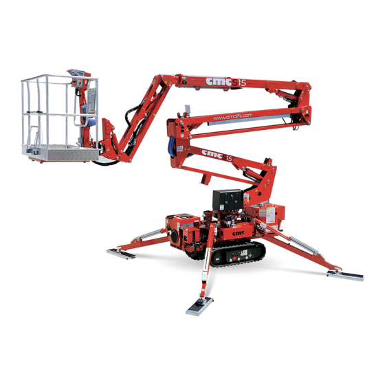
hank you for choosing to purchase a MEWP (aerial work platform)
CMC, we are sure you will be pleased with your choice.
0.1
Use and maintenance manual
This manual is added to the sold machine and contains the instructions for
its transfer, use and maintenance. While drawing up this manual, we took
into consideration all the operations that are part of a normal use and regu-
lar maintenance of the machine. So for a correct and optimum use, you
have to follow the described instructions carefully.
This manual has been drawn up in order to
Describe the use of the machine
Show the main technical specifications of the machine
Provide with the instructions for the placement and use of
the machine
Describe the safety devices
Point out the potential risks and/or possible dangerous sit-
uations
Provide with the necessary instructions for the ordinary
maintenance operations
Provide with the instructions for the filling of the check reg-
ister.
THE USE AND MAINTENANCE MANUAL IS INTEGRAL
PART OF THE MACHINE. In case of sale of the MEWP,
please give this manual to the new owner.
MAN. 161 rev. 5 Use and maintenance manual Sup15
:
*
KEY FOR THE SYMBOLS USED IN THIS MANUAL
( CAUTION)
= warns the user about the risk of serious damages to people or to
part of the equipment or the vehicle, if you do not obey the safety
regulations.
(WARNING)
= notifies the possibility of minor injuries to people or little damag-
es to the platform or vehicle PARTS..
( FORBIDDEN)
= prohibition signal
(
OBLIGATION ) = obligation signal
(CAUTION)
= warns the user about the risk of environmental
pollution.
(OPTIONAL)
= indicates an optional outfit.
( IMPORTANT NOTE)
This instruction manual is addressed to:
Operators
Ground assistants
Staff in charge of the platform (MEWP) guard
Security manager
Maintenance manager
1ª
page of
77
Advertisement
Table of Contents

Related Manuals for CMC SUP15


Summary of Contents for CMC SUP15
- Page 1 ( CAUTION) = warns the user about the risk of serious damages to people or to CMC, we are sure you will be pleased with your choice. part of the equipment or the vehicle, if you do not obey the safety regulations.
-
Page 2: Normative References
Normative references Disclaimer CMC declines all responsibility in case of partial or total non- This manual has been drawn up according to the following observance of the following instructions laws and directives: Before proceeding with any operation of installation and... - Page 3 No part of this publication can be translated, modified or reproduced (even partially) without the express authorization of CMC s.r.l. CMC reserves the right to modify - totally or partially - any datum or specifi- cation of this publication (without prior notice).
-
Page 4: Specifications
12 V max arm extension and withdrawal speed 0,4 m/s Electric engine power 2.2 kW Min and max pressure 70 / 210 bar Max rotation speed 0,7 m/s 4ª MAN. 161 rev. 5 Use and maintenance manual Sup15 page of... -
Page 5: Identification Plate
MAX MANUAL FORCE ALLOWED 40 daN MAX WIND SPEED ALLOWED 12,5 m/s MAX FRAME INCLINATION ALLOWED 1 ° EXTERNAL FEEDING 220V 50Hz Picture 1: identification plate - facsimile 5ª MAN. 161 rev. 5 Use and maintenance manual Sup15 page of... - Page 6 MEWP in rest position Picture 2: Overall drawing with basket connected 6ª MAN. 161 rev. 5 Use and maintenance manual Sup15 page of...
- Page 7 1.4 Working diagram and stabilization area Picture 3: working diagram 7ª MAN. 161 rev. 5 Use and maintenance manual Sup15 page of...
- Page 8 Picture 4 - stabilization area (mm) 8ª MAN. 161 rev. 5 Use and maintenance manual Sup15 page of...
- Page 9 Classification CE Certification The aerial work platform Sup15 belongs to the group B: during the working CMC s.r.l. states under its own responsibility that the MEWP Sup15 was de- phases, the vertical projection of the load gravity centre can be out of the signed and produced in compliance with national and European standards, turnover lines (EN 280:2009 par.
-
Page 10: Description And Purpose
Description and purpose Definition The machine is called Sup15 and it is a mobile elevating work platform (MEWP): mobile machine designed to take people to the work positions, where they carry out duties from the work platform, with the understanding that people... -
Page 11: Description Of The Main Components
Description of the main components Picture 5: MEWP main components 11ª MAN. 161 rev. 5 Use and maintenance manual Sup15 page of... - Page 12 At the end of the telescopic arm is hinged an arm named Jib. The lifting or descent of the Jib is done by operating the “Jib lifting cylinder” 10 (Picture 12ª MAN. 161 rev. 5 Use and maintenance manual Sup15 page of...
-
Page 13: Control Positions
MEWP is set in the transport configuration and it is formed by: -right rear stabilizer lever1 (Picture 6) - pushing the lever forward the stabilizer lowers. - pushing the lever backwards, the stabilizer withdraws. 13ª MAN. 161 rev. 5 Use and maintenance manual Sup15 page of... - Page 14 CW this switch has the priority on any other control; it is only possible to use the emergency lowering to the ground. 14ª MAN. 161 rev. 5 Use and maintenance manual Sup15 page of...
- Page 15 Picture 9: Platform control (exercise) position The platform control (exercise) station (Picture 9) is located inside the bas- ket, and it is formed by: 15ª MAN. 161 rev. 5 Use and maintenance manual Sup15 page of...
- Page 16 It is strictly forbidden to carry out the basket levelling opera- tion when the machine is open. - Joystick lever for turret rotation control 7 (Picture 9) - Joystick lever for extension control 8 (Picture 9) 16ª MAN. 161 rev. 5 Use and maintenance manual Sup15 page of...
- Page 17 (lever downwards) ; the movement stops at its release. - Arm extension-withdrawal 3 (Picture 10): it activates the exten- sion (lever upwards) and withdrawal (lever downwards) movement; the movement stops at its release . 17ª MAN. 161 rev. 5 Use and maintenance manual Sup15 page of...
-
Page 18: Use Procedures
Trees are broken off or uprooted, Storm 24,5-28,4 >89 tions: poor visibility, storms, lightning risk, etc.. heavy damages to buildings Table 1: Beaufort wind scale Do not to operate inside refrigerating rooms. 18ª MAN. 161 rev. 5 Use and maintenance manual Sup15 page of... - Page 19 Over 87.5 kV, not over 121 kV / 4 ft. 0 in. (122 cm), Over 121 kV, not over 140 kV / 4 ft. 6 in. (137 cm). 19ª MAN. 161 rev. 5 Use and maintenance manual Sup15 page of...
- Page 20 WARNING: in both cases, i.e. choosing one of the two meth- ods, the user shall remove the basket: this to help the operations and reduce the encumbrances. Picture 11: harness 20ª MAN. 161 rev. 5 Use and maintenance manual Sup15 page of...
- Page 21 Picture 12: basket joint - pin and splint pin 21ª MAN. 161 rev. 5 Use and maintenance manual Sup15 page of...
- Page 22 12). This will automatically enable the crawlers translation station (par. 3.2 Picture 7) provided that the cabled remote control is cor- rectly fastened to its connection. 22ª MAN. 161 rev. 5 Use and maintenance manual Sup15 page of...
- Page 23 If you have to climb, the basket has to be positioned at the If you have to descend, the basket has to be positioned at the back front Picture 16 – translation direction downward Picture 15 – translation direction upward 23ª MAN. 161 rev. 5 Use and maintenance manual Sup15 page of...
- Page 24 Secure the machine to the truck plane by the junctions on the base cart. Make sure the machine is turned off during transportation 24ª MAN. 161 rev. 5 Use and maintenance manual Sup15 page of...
- Page 25 Picture 18: endothermic engine start key button (5 Picture 7) and right crawler operation button (6 Picture 7). 2. If you want to use the electrical engine: 25ª MAN. 161 rev. 5 Use and maintenance manual Sup15 page of...
- Page 26 If such conditions are not met, it is strictly for- bidden to use the MEWP. Place the MEWP on the selected area; 26ª MAN. 161 rev. 5 Use and maintenance manual Sup15 page of...
- Page 27 24 and 4 Picture 9 respectively indicating “stabiliza- Picture 22: basket coupling tion” and “consent to the operation of the platform aerial part”. At the same time the two lights 3 and 4 27ª MAN. 161 rev. 5 Use and maintenance manual Sup15 page of...
- Page 28 First lift the pantograph in order to rise from the support. It is therefore strictly forbidden to rotate the turret as first movement since it could cause heavy damages to the carpentry. 28ª MAN. 161 rev. 5 Use and maintenance manual Sup15 page of...
-
Page 29: Emergency Operations
First close the platform by unfastening the hydraulic handle 2 (Picture 24) near the hydraulic seat in picture and start closing the MEWP. Picture 23: emergency station closing carter 29ª MAN. 161 rev. 5 Use and maintenance manual Sup15 page of... - Page 30 (Picture 24) and start destabilizing the MEWP . While the ground operator activates the pump (after inserting the supplied lever ), the other operator carries out the destabilizing operations, activating the stabilizers control sta- tion levers. 30ª MAN. 161 rev. 5 Use and maintenance manual Sup15 page of...
- Page 31 Another operator first removes the deal seal from the golden lock ring, then the ring, then screws the cursor of the left ex- change electrovalve 1S (Picture 26); 31ª MAN. 161 rev. 5 Use and maintenance manual Sup15 page of...
- Page 32 WEARING ALL PPES PROVIDED FOR BY LAW. AFTER CARRYING OUT ALL THE NECESSARY OPERATIONS TO RESET THE REST CONDITION AND TO CLOSE THE MEWP, CONTACT THE NEAREST SERVICE CENTRE FOR TECHNICAL SUPPORT. 32ª MAN. 161 rev. 5 Use and maintenance manual Sup15 page of...
-
Page 33: Safety Rules
• Some of the platform components (integrated groups for the stabilizers, max pressure valve on the turret) which are important for the safety of the MEWP, are calibrated in CMC s.r.l. factory and the containers are THE NON-OBSERVANCE OF ONE OF THE FOLLOWING sealed before the delivery of the MEWP to the customer. - Page 34 In case of particular works (pruning, plants maintenance etc.) it is dangerous conditions are over; forbidden to let trunks, pipes, poles etc. fall inside the basket or on the MEWP structure: they can severely impair the MEWP stability; 34ª MAN. 161 rev. 5 Use and maintenance manual Sup15 page of...
- Page 35 • It is forbidden to use ladders or tables on the basket in order to increase the MEWP’s outreach or working height; 35ª MAN. 161 rev. 5 Use and maintenance manual Sup15 page of...
-
Page 36: Safety Devices
Do not trust the functioning of these devices to value their working and safety conditions; the operator is in any case responsible for a proper and responsible use of the machine. 36ª MAN. 161 rev. 5 Use and maintenance manual Sup15 page of... - Page 37 In case of absence or de- cay of the marks, contact the Servicing. Picture 28: working diagram Picture 27: identification plate (example) 37ª MAN. 161 rev. 5 Use and maintenance manual Sup15 page of...
- Page 38 Picture 29: stabilizers controls Picture 30: platform controls (basket work station) 38ª MAN. 161 rev. 5 Use and maintenance manual Sup15 page of...
- Page 39 Picture 31: platform control (emergency position) Picture 32: emergency turnout Picture 33: parking operations box 39ª MAN. 161 rev. 5 Use and maintenance manual Sup15 page of...
- Page 40 Picture 36 – parking dead man button Picture 34: main box Picture 37 Picture 35 – selector for translation/stabilization 40ª MAN. 161 rev. 5 Use and maintenance manual Sup15 page of...
- Page 41 Over 27.97 mph wind force (grade 6) Picture 38 stop using the lifting machine immedi- ately! Picture 40 Picture 39 Picture 41 41ª MAN. 161 rev. 5 Use and maintenance manual Sup15 page of...
- Page 42 CAPACITE M AXIM ALE: MAX TRAGFAEHIGKEIT: 40Kg 80Kg 80Kg CAPACIDAD M AXIM A: 2 0 0 K g MAX BELASTIN G: Picture 43: max capacity allowed in the basket 42ª MAN. 161 rev. 5 Use and maintenance manual Sup15 page of...
- Page 43 S A F E T Y- B E L T L I N K A G E Picture 50: shearing and cutting hazard Picture 48: indicates the position of the safety belts fastening rings 43ª MAN. 161 rev. 5 Use and maintenance manual Sup15 page of...
- Page 44 Picture 51: instability hazard in case of soft ground Picture 53: prohibition signs on the machine Picture 52: warning signs on the machine Picture 54: max load and specific pressure on the stabilizers 44ª MAN. 161 rev. 5 Use and maintenance manual Sup15 page of...
- Page 45 Figure 56 – adhesive arrows on frame Figure 55 - aerial work platform use guidelines 45ª MAN. 161 rev. 5 Use and maintenance manual Sup15 page of...
-
Page 46: Electrical System
Non-authorized staff shall not replace any of the components. Many components have been calibrated: a correct calibration of these parts (possible only in CMC or in authorized workshops) is necessary to ensure the safety of the machine.. MEWP is electrically fed, automatically, when the power take-off control is operated and the parking brake is engaged. -
Page 47: Hydraulic System
Non-authorized staff shall not replace any of the components. Many components have been calibrated: a correct calibration of these parts (possible only in CMC or in authorized workshops) is necessary to ensure the safety of the machine. 47ª... -
Page 48: Maintenance
The operations indicated with CMC shall be performed only by CMC or in its authorized workshops. Use only CMC original spare parts (even if on the market there are equiva- lent or similar parts). The frequency of the maintenances is indicated in the relevant table. By this frequency we mean a normal use of the equipment;... -
Page 49: Daily Maintenance
“Trouble- gine; shooting”, Operate the lever for strictly forbidden the lifting and lowering to use the MEWP. of the stabilizers; Contact the Ser- STABILIZERS SHALL NOT MOVE vicing. 49ª MAN. 161 rev. 5 Use and maintenance manual Sup15 page of... - Page 50 Operate the levers for the lift- the MEWP. Con- ing and lowering of the tele- tact the Servicing scopic arm; TELESCOPIC SHALL NOT MOVE 50ª MAN. 161 rev. 5 Use and maintenance manual Sup15 page of...
- Page 51 Check that the electrical contacts are tions not slacken Check that there are no trace of clashes on the equipment It is strictly forbidden to use the MEWP. Con- tact the Servicing 51ª MAN. 161 rev. 5 Use and maintenance manual Sup15 page of...
-
Page 52: Weekly Maintenance
Check the right positioning and integrity of the stickers USER / CMC Check that there are no consumption signals and/or corro- USER / CMC sion signal on the paint of the hydraulic couplings. 52ª MAN. 161 rev. 5 Use and maintenance manual Sup15 page of... - Page 53 Check the tightening of the bolts of the bearing, the USER / CMC Replacement of the hydraulic filters USER / CMC geared motor and the frame Registration of the movement of the arms 53ª MAN. 161 rev. 5 Use and maintenance manual Sup15 page of...
- Page 54 N.B.: The dipstick is placed inside the oil tank cap. The tank is placed on the back of the turret base. The hydraulic filters are placed on the sides of the stabilizers control station. 54ª MAN. 161 rev. 5 Use and maintenance manual Sup15 page of...
-
Page 55: Biennial Maintenance
Complete check of the whole machine and note the Complete check of the whole machine and note the results in the appropriate manual section results in the appropriate manual section 55ª MAN. 161 rev. 5 Use and maintenance manual Sup15 page of... -
Page 56: Safety Rules During Maintenance
• To assure the safety of the machine the use of original spare parts installed by CMC or by authorized repair shops is compul- sory: in fact some components can be calibrated only in CMC or in authorized workshops. •... - Page 57 Do not disperse the exhausted oil or other consumables in the envi- ronment, but put them in the specially provided containers and give them to the authorized collection centres. 57ª MAN. 161 rev. 5 Use and maintenance manual Sup15 page of...
- Page 58 Non authorized staff is not allowed to replace the components. Many components have been calibrated: a correct calibration of these parts (which is possible only in CMC or in authorized repair shops) is necessary to assure the safety of the machine.
-
Page 59: Troubleshooting
Many components of the MEWP have been calibrated: a correct cali- If the problem persists, contact the servicing bration of these parts (which is possible only in CMC or in authorized repair shops) is necessary to assure the safety of the machine. -
Page 60: Control Register
Periodical checks and maintenance journal (par. 10.9) established with the technical, dimensional and functional features indicated in the use manual Notes (par. 10.10) date 02/07/13 CMC s.r.l. __________________________ 60ª MAN. 161 rev. 5 Use and maintenance manual Sup15 page of... - Page 61 The seller The buyer The seller The buyer ___________________________________________________________ ___________________________________________________________ 61ª MAN. 161 rev. 5 Use and maintenance manual Sup15 page of...
- Page 62 Date…………………….……… Stamp and signature of the responsible Stamp and signature of the responsible for the firm in charge The user for the firm in charge The user ___________________________________________________________ 62ª MAN. 161 rev. 5 Use and maintenance manual Sup15 page of...
- Page 63 Place…………………………. Date…………………….……… Stamp and signature of the responsible Stamp and signature of the responsible for the firm in charge The user for the firm in charge The user 63ª MAN. 161 rev. 5 Use and maintenance manual Sup15 page of...
- Page 64 Place…………………………. Date…………………….……… Stamp and signature of the responsible Stamp and signature of the responsible for the firm in charge The user for the firm in charge The user 64ª MAN. 161 rev. 5 Use and maintenance manual Sup15 page of...
- Page 65 Place…………………………. Date…………………….……… Stamp and signature of the responsible Stamp and signature of the responsible for the firm in charge The user for the firm in charge The user 65ª MAN. 161 rev. 5 Use and maintenance manual Sup15 page of...
- Page 66 Place…………………………. Date…………………….……… Stamp and signature of the responsible for the firm in charge The user Stamp and signature of the responsible for the firm in charge The user 66ª MAN. 161 rev. 5 Use and maintenance manual Sup15 page of...
- Page 67 Place…………………………. Date………………….……….… Stamp and signature of the responsible for the firm in charge The user Stamp and signature of the responsible for the firm in charge The user 67ª MAN. 161 rev. 5 Use and maintenance manual Sup15 page of...
- Page 68 Periodical checks and maintenance journal DESCRIPTION OF THE DATE SIGNATURE INTERVENTION The user shall observe the maintenance and control program described in this manual. DESCRIPTION OF THE DATE SIGNATURE INTERVENTION 68ª MAN. 161 rev. 5 Use and maintenance manual Sup15 page of...
- Page 69 DESCRIPTION OF THE DESCRIPTION OF THE DATE SIGNATURE DATE SIGNATURE INTERVENTION INTERVENTION 69ª MAN. 161 rev. 5 Use and maintenance manual Sup15 page of...
- Page 70 …………………………………………………………………………………… 10.10 Notes …………………………………………………………………………………… …………………………………………………………………………………… …………………………………………………………………………………… …………………………………………………………………………………… …………………………………………………………………………………… …………………………………………………………………………………… …………………………………………………………………………………… …………………………………………………………………………………… …………………………………………………………………………………… …………………………………………………………………………………… …………………………………………………………………………………… …………………………………………………………………………………… …………………………………………………………………………………… …………………………………………………………………………………… 70ª MAN. 161 rev. 5 Use and maintenance manual Sup15 page of...
- Page 71 10.11 Maintenance of tracked undercarria- 71ª MAN. 161 rev. 5 Use and maintenance manual Sup15 page of...
- Page 72 72ª MAN. 161 rev. 5 Use and maintenance manual Sup15 page of...
- Page 73 73ª MAN. 161 rev. 5 Use and maintenance manual Sup15 page of...
- Page 74 74ª MAN. 161 rev. 5 Use and maintenance manual Sup15 page of...
- Page 75 75ª MAN. 161 rev. 5 Use and maintenance manual Sup15 page of...
- Page 76 76ª MAN. 161 rev. 5 Use and maintenance manual Sup15 page of...
- Page 77 10.7 Considerable failures and relevant repairs MEWP use procedures 10.8 Periodical checks and maintenance journal Emergency operations 10.9 Notes Safety rules 10.10 Maintenance of tracked undercarriages Safety devices 77ª MAN. 161 rev. 5 Use and maintenance manual Sup15 page of...
Need help?
Do you have a question about the SUP15 and is the answer not in the manual?
Questions and answers