Table of Contents
Advertisement
Available languages
Available languages
Quick Links
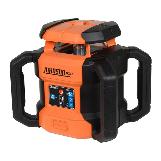
4000' Dual Slope Rotary Laser
Models JRT300-RDHV-S & JRT300-RDHV-K Red
Model JRT300-GNHV-K Green
Instruction Manual
Congratulations on your choice of this 4000' Dual Slope Rotary
Laser Level. We suggest you read this instruction manual thoroughly
before using the instrument. Save this instruction manual for future
use.
This is a Class 3R laser tool and is manufactured to comply with
CRF 21, parts 1040.10 and 1040.11 as well as international safety rule
IEC 285.
©2023 Johnson Level & Tool - REV 1
1
Advertisement
Chapters
Table of Contents

Subscribe to Our Youtube Channel
Related Manuals for Johnson JRT300-GNHV-K Green


Summary of Contents for Johnson JRT300-GNHV-K Green
- Page 1 Save this instruction manual for future use. This is a Class 3R laser tool and is manufactured to comply with CRF 21, parts 1040.10 and 1040.11 as well as international safety rule IEC 285. ©2023 Johnson Level & Tool - REV 1...
-
Page 2: Table Of Contents
4000' Dual Slope Rotary Laser Alkaline Battery Compartment (batteries not included) Lithium-ion Batteries Detector with Clamp and 2 “AAA” Alkaline Batteries Remote with 2 “AAA” Alkaline Batteries Magnetic Target Type C, USB Adapter/Charger Hard-Shell Carrying Case ©2023 Johnson Level & Tool - REV 1... - Page 3 4000' Dual Slope Rotary Laser Alkaline Battery Compartment (batteries not included) Lithium-ion Batteries Detector with 2 “AAA” Alkaline Batteries Remote with 2 “AAA” Alkaline Batteries Magnetic Target Track Mount Type C, USB Adapter/Charger Hard-Shell Carrying Case ©2023 Johnson Level & Tool - REV 1...
-
Page 4: Safety Instructions
• Do not attempt to view the laser beam through optical tools such as telescopes as serious eye injury may result. • Always turn the laser tool off when not in use or left unattended for a period of time. ©2023 Johnson Level & Tool - REV 1... -
Page 5: Getting Started
Figure 2 4. When charged using this method, the battery charge is indicated by LED light “b”. See Operating Panel Overview. Green = ≥30% Red = 10% ≤ ≥30% Flashing Red = ≤10% ©2023 Johnson Level & Tool - REV 1... - Page 6 Push in and turn the battery lock knob clockwise to the “Unlock” position. (Figure 4) Figure 4 2. Remove battery compartment from rotary laser. (Figure 5) 3. Remove each battery case from the battery compartment. Figure 5 ©2023 Johnson Level & Tool - REV 1...
- Page 7 Fuel Gauge LED1 LED2 LED3 Volt of battery < 3.6V Flashing 3.6V ≤ Volt of battery <3.9V Flashing 3.9V ≤ Volt of battery Flashing 4.165V ≤ Volt of battery <4.235 (fully charged) ©2023 Johnson Level & Tool - REV 1...
- Page 8 NOTE: Always check that the battery compartment lock knob is in the “Unlock” position before removing and/or replacing batteries. Push in and turn the battery lock knob clockwise to the “Unlock” position. (Figure 11) Figure 11 ©2023 Johnson Level & Tool - REV 1...
- Page 9 Be sure the end with the openings is aligned with the opening on the rear of the battery compartment. (Figure 14) Figure 14 6. Reinsert the battery compartment into the rotary laser. (Figure 15) Figure 15 ©2023 Johnson Level & Tool - REV 1...
- Page 10 Type C, USB adapter/charger power cord or power bank to the rotary laser using the battery recharge port, and connect the opposite end of charging cable to a power source. ©2023 Johnson Level & Tool - REV 1...
- Page 11 2. Rotation Speed Selection button (600rpm-1200rpm-0-100rpm-300rpm) 3. Line Operation and Length Operation button (15°, 30°, 60°, 0°) 4. Shock Warning Indicator button 5. Dual-Axis Slope Operation button 6. Upper/Clockwise Direction button 7. Lower/Counterclockwise Direction button ©2023 Johnson Level & Tool - REV 1...
- Page 12 MORE THAN 5° out of level Green Y axis leveling Y axis adjustments Y axis leveling adjustment complete adjustment activated (Press deactivated Dual-Axis Slope Operation button twice) MORE THAN 5° out of level ©2023 Johnson Level & Tool - REV 1...
-
Page 13: Warning Labels
Rayonnement laser. Ne regardez pas directe-ment dans le faisceau. Produit laser de classe 3R. Conforme à 21 CFR 1040.10 et 1040.11, sauf pour ©2023 JOHNSON LEVEL & TOOL MFG. CO., INC. les écarts suivant l´avis laser 50, 24/6/2007 MEQUON, WI 53092... -
Page 14: Parts/Components
Laser Line Output Window Y-Calibration X-Calibration Guide Guide Hand Grips Rotating Laser Output Window Keypad Battery Recharge Port 5/8"-11 Screw Thread Battery Lock 5/8"-11 Screw Thread and Cover and Laser Output Window ©2023 Johnson Level & Tool - REV 1... -
Page 15: Operation Instructions
See section 7. Using the Rotary Laser 1. Horizontal or Vertical Position The Johnson Rotary Laser can be used in either a horizontal or vertical orientation, depending on your needs. Horizontal Laser Beam Position... - Page 16 Adjust the rotating laser position as directed by the indicator in the corresponding direction until the X and/or Y LED turns off and only the “c” LED flashes. Continue leveling the unit until indicator “c” is steady green. ©2023 Johnson Level & Tool - REV 1...
- Page 17 2. In Point/Line Segment mode, press button to adjust the position of the laser line clockwise or press button to adjust the position of the laser line counterclockwise. 3. Press the button to exit Point/Line Segment Mode. ©2023 Johnson Level & Tool - REV 1...
- Page 18 The LED “e” will illuminate a steady green. The automatic leveling mode is off, and the rotary laser can be placed at any angle. 2. Press the button for three seconds to exit Manual mode and return to Automatic mode. ©2023 Johnson Level & Tool - REV 1...
- Page 19 When the laser beam reaches the desired position, press the button to finish adjustments. All three LED lights will illuminate steady green. ©2023 Johnson Level & Tool - REV 1...
- Page 20 2. Upper/Clockwise Direction button 3. Rotation Speed Selection button (600rpm-1200rpm-0-100rpm-300rpm) 4. Line Operation and Length Operation button (15°, 30°, 60°, 0°) 5. Shock Warning Indicator button 6. Dual-Axis Slope Operation button 7. Battery Compartment ©2023 Johnson Level & Tool - REV 1...
- Page 21 If unit comes into contact with water or other liquids, wipe it dry immediately. • Do not use unit around fire or expose it to fire in any way. ©2023 Johnson Level & Tool - REV 1...
- Page 22 3. Fine/Coarse Detection Button 4. Detecting Window 5. Reference Marker 6. Volume Clamp Bracket Slots 2. Magnet Front 3. Battery Compartment Back JLR100-RT-RD 4. Magnet 5. Rear Signal Indicator Window JLR100-RT-RD shown ©2023 Johnson Level & Tool - REV 1...
- Page 23 “AAA” alkaline batteries according to the polarity illustrated inside. (Figure 19) Figure 19 NOTE: Take the batteries out when the unit is not in use for a long time. ©2023 Johnson Level & Tool - REV 1...
- Page 24 5. Connecting to the Clamp Slide the clamp bracket into the support bracket on the back side of the unit. (Figure 21) Front Back JLR100-RT-RD Figure 21 ©2023 Johnson Level & Tool - REV 1...
- Page 25 It has measurements in both English and Metric scales (inches/cm). Targets are available for both red and green laser levels. (Figure 22) Figure 22 ©2023 Johnson Level & Tool - REV 1...
- Page 26 (Figure 25) Figure 25 4. Slide the detector onto the support bracket until it snaps into place. Refer to “Connecting to the Clamp” on page 24. ©2023 Johnson Level & Tool - REV 1...
- Page 27 0" to 1". (Figure 26) 6. Use the level bullseye to verify the clamp and detector are level to the surface. Figure 26 ©2023 Johnson Level & Tool - REV 1...
- Page 28 (Figure 27) NOTE: There are two ways to mount the track mount accessory to a track: with or without the laser attached. The following pages describe each method. Figure 27 ©2023 Johnson Level & Tool - REV 1...
- Page 29 (Figure 30) Figure 30 4. With laser attached, slide laser mount on to track mount until it clicks into place. (Figure 31) Figure 31 ©2023 Johnson Level & Tool - REV 1...
- Page 30 4. Place the track mount accessory onto a track, making sure the clamp is fully seated over the track. Tighten the smaller adjustment knob to secure the track mount accessory to the track. (Figure 35) Figure 35 ©2023 Johnson Level & Tool - REV 1...
- Page 31 Turn the knob on the leveling screw to help ensure the position of the unit is level. The leveling screw has a non-mar rubber foot to prevent damage to surfaces. (Figure 37) Figure 37 ©2023 Johnson Level & Tool - REV 1...
-
Page 32: Accuracy Check
11. If the distance between points Ay and By is more than 1/32" at 50', the laser is out of calibration. 12. If the rotary laser fails step 8 or step 11, contact our Customer Service Department at 888-953-8357. ©2023 Johnson Level & Tool - REV 1... -
Page 33: Specifications
8" H x 9.5" W x 7" D Working Temperature 14°F to 113°F Tripod Thread 5/8"–11 Rotation Speeds 0 rpm, 100 rpm, 300 rpm, 600 rpm, or 1200 rpm IP Protection IP67 ©2023 Johnson Level & Tool - REV 1... -
Page 34: Care And Handling
10. Product Warranty & Registration Johnson Level & Tool offers a five year limited warranty on this product. You can obtain a copy of the limited warranty for a Johnson Level & Tool product by contacting Johnson Level & Tool's Customer Service Department, as provided below, or by visiting our web site at www.johnsonlevel.com. -
Page 35: Accessories
To register, go to www.johnsonlevel.com/register. 11. Accessories Johnson® accessories and replacement parts are available for purchase through authorized Johnson® dealers. Use of non-Johnson® accessories and replacement parts will void any applicable limited warranty and there will be NO WARRANTY. If you need any assistance in locating any accessories, please contact our Customer Service Department at 888-953-8357. -
Page 36: Trouble Shooting
Ambient temperature Ensure temperature too high/low is within operating range listed under specifications Beam is difficult to Speed too low Turn laser RPM to a detect with laser higher speed detector ©2023 Johnson Level & Tool - REV 1... - Page 37 ©2023 Johnson Level & Tool - REV 1...
- Page 38 Mode d’emploi Félicitations d’avoir choisi ce niveau laser rotatif à double pente de 1 219 m. Johnson Level & Tool recommande de lire ce mode d’emploi avec attention avant d’utiliser l’instrument. Conserver ce mode d’emploi pour pouvoir le consulter ultérieurement.
- Page 39 Compartiment pour piles alcalines (piles non fournies) Piles au lithium-ion Détecteur avec dispositif de serrage et 2 piles alcalines AAA Télécommande et 2 piles alcalines AAA Cible magnétique Adaptateur/chargeur USB de type C Étui de transport rigide ©2023 Johnson Level & Tool - REV 1...
- Page 40 Compartiment pour piles alcalines (piles non fournies) Piles au lithium-ion Détecteur et 2 piles alcalines AAA Télécommande et 2 piles alcalines AAA Cible magnétique Montage sur rail Adaptateur/chargeur USB de type C Étui de transport rigide ©2023 Johnson Level & Tool - REV 1...
-
Page 41: Consignes De Sécurité
• Veiller à toujours éteindre l’outil laser lorsqu’il n’est pas utilisé ou qu’il est laissé sans surveillance pendant une certaine période. ©2023 Johnson Level & Tool - REV 1... -
Page 42: Pour Commencer
4. Avec cette méthode, la charge des piles est indiquée par le voyant « b ». Voir la vue d’ensemble du tableau de commande. Vert = ≥ 30 % Rouge = 10 % ≤ ≥ 30 % Rouge clignotant = ≤ 10 % ©2023 Johnson Level & Tool - REV 1... - Page 43 (Figure 4) Figure 4 2. Retirer le compartiment de piles du laser rotatif. (Figure 5) 3. Retirer chaque boîtier de pile du compartiment de piles. Figure 5 ©2023 Johnson Level & Tool - REV 1...
- Page 44 Tension de pile < 3,6 V Clignotant ÉTEINT ÉTEINT 3,6 V ≤ tension de pile < 3,9 V ALLUMÉ Clignotant ÉTEINT 3,9 V ≤ tension de pile ALLUMÉ ALLUMÉ Clignotant 4,165 V ≤ tension de pile < 4,235 V ALLUMÉ ALLUMÉ ALLUMÉ (charge complète) ©2023 Johnson Level & Tool - REV 1...
- Page 45 Enfoncer et tourner le bouton de verrouillage de piles dans le sens horaire vers la position de déverrouillage (Figure 11) Figure 11 ©2023 Johnson Level & Tool - REV 1...
- Page 46 Veiller à ce que l’extrémité munie d’ouvertures soit alignée avec l’ouverture sur l’arrière du compartiment de piles. (Figure 14) Figure 14 6. Réinsérer le compartiment de piles dans le laser rotatif. (Figure 15) Figure 15 ©2023 Johnson Level & Tool - REV 1...
- Page 47 USB de type C ou une batterie externe au laser rotatif à l’aide du port de recharge de piles, et de brancher l’extrémité opposée du câble de charge à une source d’alimentation. ©2023 Johnson Level & Tool - REV 1...
- Page 48 3. Touche d’utilisation de ligne et d’utilisation de longueur (15°, 30°, 60°, 0°) 4. Touche d’indication d’avertissement de choc 5. Touche d’utilisation de pente d’axe double 6. Touche de direction supérieure/dans le sens horaire Touche de direction inférieure/dans le sens antihoraire ©2023 Johnson Level & Tool - REV 1...
- Page 49 Réglages d’axe Y Réglage mise de niveau terminés de mise de d’axe Y activé niveau d’axe Y (appuyer deux désactivé fois sur la touche d’utilisation de pente d’axe double) Rouge PLUS DE 5° hors niveau ©2023 Johnson Level & Tool - REV 1...
-
Page 50: Étiquettes De Mise En Garde
Rayonnement laser. Ne regardez pas directe-ment dans le faisceau. Produit laser de classe 3R. Conforme à 21 CFR 1040.10 et 1040.11, sauf pour ©2023 JOHNSON LEVEL & TOOL MFG. CO., INC. les écarts suivant l´avis laser 50, 24/6/2007 MEQUON, WI 53092... -
Page 51: Pièces/Composants
Clavier Port de recharge de pile Filetage de vis 5/8 po-11 Verrouillage et Filetage de vis 5/8 po-11 couvercle de piles et fenêtre de sortie de laser ©2023 Johnson Level & Tool - REV 1... -
Page 52: Consignes D'utilisation
Voir la section 7. Utilisation du laser rotatif 1. Position horizontale ou verticale Le laser rotatif Johnson peut être utilisé dans une orientation horizontale ou verticale, selon les besoins. Position de faisceau laser horizontale Placer le laser rotatif en position verticale, soit posé... - Page 53 « c » clignote. Poursuivre la mise de niveau de l’appareil jusqu’à ce que le voyant « c » soit allumé en vert en continu. ©2023 Johnson Level & Tool - REV 1...
- Page 54 3. Appuyer sur la touche pour quitter le mode point/segment de ligne. ©2023 Johnson Level & Tool - REV 1...
- Page 55 être placé à n’importe quel angle. 2. Appuyer sur la touche pendant trois secondes pour quitter le mode manuel et revenir au mode automatique. ©2023 Johnson Level & Tool - REV 1...
- Page 56 Lorsque le faisceau laser atteint la position souhaitée, appuyer sur la touche pour terminer les réglages. Les trois voyants s’allument alors en vert en continu. ©2023 Johnson Level & Tool - REV 1...
- Page 57 (600 tr/min-1 200 tr/min-0-100 tr/min- 300 tr/min) 4. Touche d’utilisation de ligne et d’utilisation de longueur (15°, 30°, 60°, 0°) 5. Touche d’indication d’avertissement de choc 6. Touche d’utilisation de pente d’axe doublen Compartiment de piles ©2023 Johnson Level & Tool - REV 1...
- Page 58 Si elle entre en contact avec de l’eau ou d’autres liquides, l’essuyer immédiatement. • Ne pas l’utiliser à proximité d’un feu et ne l’exposer en aucun cas à du feu. ©2023 Johnson Level & Tool - REV 1...
- Page 59 5. Repère de référence 6. Volume Fentes de support de dispositif de serrage 2. Aimant 3. Compartiment de piles Front Back JLR100-RT-RD 4. Aimant 5. Fenêtre d’indication de signal arrière JLR100-RT-RD illustré ©2023 Johnson Level & Tool - REV 1...
- Page 60 AAA selon la polarité illustrée à l’intérieur. (Figure 19) Figure 19 REMARQUE : Retirer les piles si l’appareil ne doit pas être utilisé pendant une durée prolongée. ©2023 Johnson Level & Tool - REV 1...
- Page 61 5. Raccordement au dispositif de serrage Faire glisser le support du dispositif de serrage dans le support de fixation sur le côté arrière Front Back JLR100-RT-RD de l’appareil. (Figure 21) Figure 21 ©2023 Johnson Level & Tool - REV 1...
- Page 62 être fixée facilement à des surfaces ferreuses dans une position horizontale ou verticale. Elle comporte des mesures en unités anglaises ou métriques (pouces/centimètres). Des cibles sont disponibles pour les niveaux laser rouge et vert. (Figure 22) Figure 22 ©2023 Johnson Level & Tool - REV 1...
- Page 63 Figure 25 soit solidement fixé. (Figure 25) 4. Faire glisser le détecteur sur le support de fixation jusqu’à entendre un clic. Se reporter à « Raccordement au dispositif de serrage » sur la page 24. ©2023 Johnson Level & Tool - REV 1...
- Page 64 0 à 25,4 mm. (Figure 26) 6. Se servir du niveau sphérique pour vérifier que le dispositif de serrage et le détecteur sont de niveau avec la surface. Figure 26 ©2023 Johnson Level & Tool - REV 1...
- Page 65 (Figure 27) REMARQUE : Il existe deux façons de monter l’accessoire de montage sur rail sur un rail : avec ou sans le laser fixé. Les pages suivantes décrivent chaque méthode. Figure 27 ©2023 Johnson Level & Tool - REV 1...
- Page 66 (Figure 30) Figure 30 4. Une fois le laser fixé, faites glisser le support du laser sur le support du rail jusqu’à ce qu’il s’enclenche. (Figure 31) Figure 31 ©2023 Johnson Level & Tool - REV 1...
- Page 67 Serrez le plus petit bouton de réglage pour fixer l’accessoire de montage sur rail au rail. (Figure 35) Figure 35 ©2023 Johnson Level & Tool - REV 1...
- Page 68 à niveau afin de vous assurer que la position de l’appareil soit de niveau. La vis de nivellement est dotée d’un pied en caoutchouc non marquant afin d’éviter d’endommager les surfaces. (Figure 37) Figure 37 ©2023 Johnson Level & Tool - REV 1...
-
Page 69: Vérification De La Précision
11. Si la distance entre les points Ay et By est supérieure à 0,8 mm à 15,2 m, le laser est mal étalonné. 12. Si les étapes 8 ou 11 ont échoué, communiquer avec le service à la clientèle au 888-953-8357. ©2023 Johnson Level & Tool - REV 1... -
Page 70: Caractéristiques Techniques
H 203 mm x l 241 mm x P 178 mm Température de -10 °C à +45 °C fonctionnement Filetage pour trépied 5/8 po-11 Vitesses de rotation 0 tr/min, 100 tr/min, 300 tr/min, 600 tr/min ou 1 200 tr/min. Indice de protection IP67 ©2023 Johnson Level & Tool - REV 1... -
Page 71: Entretien Et Manipulation
10. Garantie et enregistrement du produit Johnson Level & Tool offre une garantie limitée de cinq ans sur ce produit. Il est possible d’obtenir une copie de la garantie limitée d’un produit Johnson Level &... -
Page 72: Accessoires
à disposition pour une intervention dans le cadre de la garantie même en cas de perte du reçu, et de communiquer avec les clients si jamais un rappel de produit est nécessaire. Johnson Level & Tool ne vendra jamais les renseignements sur les clients et ne leur enverra des informations commerciales que s’ils y ont consenti. -
Page 73: Dépannage
Le faisceau est difficile à Vitesse trop faible Sélectionner une vitesse détecter avec le détecteur (tr/min) de laser plus laser élevée ©2023 Johnson Level & Tool - REV 1... - Page 74 Esta es una herramienta láser de clase 3R y está fabricada para cumplir con CRF 21, partes 1040.10 y 1040.11, así como la norma de seguridad internacional IEC 285. ©2023 Johnson Level & Tool - REV 1...
- Page 75 Baterías de iones de litio Detector con pinza y 2 baterías alcalinas “AAA” Control remoto con 2 baterías alcalinas “AAA” Objetivo magnético Adaptador/cargador USB Tipo C Estuche de transporte de carcasa dura ©2023 Johnson Level & Tool - REV 1...
- Page 76 Baterías de iones de litio Detector con 2 baterías alcalinas “AAA” Control remoto con 2 baterías alcalinas “AAA” Objetivo magnético Montaje en riel Adaptador/cargador USB Tipo C Estuche de transporte de carcasa dura ©2023 Johnson Level & Tool - REV 1...
- Page 77 • No intente ver el haz del láser a través de herramientas ópticas como telescopios, ya que se podrían provocar lesiones oculares graves. • Apague siempre la herramienta láser cuando no esté en uso o cuando la deje desatendida durante un período de tiempo. ©2023 Johnson Level & Tool - REV 1...
- Page 78 4. Cuando se carga utilizando este método, la carga de la batería se indica mediante la luz LED “b”. Consulte Descripción general del panel de operaciones. Verde = ≥ 30 % Rojo = 10 % ≤ ≥ 30 % Rojo intermitente = ≤ 10 % ©2023 Johnson Level & Tool - REV 1...
- Page 79 “UNLOCK” (desbloqueo) . (Figura 4) Figura 4 2. Retire el compartimento de la batería del láser rotativo. (Figura 5) 3. Retire cada caja de la batería del compartimento de la batería. Figura 5 ©2023 Johnson Level & Tool - REV 1...
-
Page 80: Figura 6
APAGADO APAGADO 3.6 V ≤ voltios de batería < 3.9 V ENCENDIDO Intermitente APAGADO 3.9 V ≤ voltios de batería ENCENDIDO ENCENDIDO Intermitente 4.165 V ≤ voltios de la batería ENCENDIDO ENCENDIDO ENCENDIDO <4.235 (completamente cargada) ©2023 Johnson Level & Tool - REV 1... -
Page 81: Presione Y Gire La Perilla De Bloqueo De La Batería Hacia La Derecha Hasta La Posición
“UNLOCK” (desbloqueo) antes de retirar o cambiar las baterías. Presione y gire la perilla de bloqueo de la batería hacia la derecha hasta la posición “UNLOCK” (desbloqueo) . (Figura 11) Figura 11 ©2023 Johnson Level & Tool - REV 1... -
Page 82: Retire Cada Caja De La Batería Del Compartimento De La Batería
(Figura 14) Figura 14 6. Vuelva a insertar el compartimento de las baterías en el láser rotativo. (Figura 15) Figura 15 ©2023 Johnson Level & Tool - REV 1... -
Page 83: Figura 16
USB tipo C o un banco de alimentación al láser rotativo mediante el puerto de recarga de la batería y conectar el extremo opuesto del cable de carga a una fuente de alimentación. ©2023 Johnson Level & Tool - REV 1... - Page 84 (15°, 30°, 60°, 0°) 4. Botón del indicador de advertencia de golpe 5. Botón de funcionamiento en pendiente con dos ejes 6. Botón de dirección ascendente/hacia la derecha Botón de dirección de descenso/hacia la izquierda ©2023 Johnson Level & Tool - REV 1...
- Page 85 Ajuste de nivelación del eje Y completados nivelación del eje Y activado (presione desactivado dos veces el botón de funcionamiento en pendiente con dos ejes) Rojo MÁS DE 5° fuera del nivel ©2023 Johnson Level & Tool - REV 1...
- Page 86 Rayonnement laser. Ne regardez pas directe-ment dans le faisceau. Produit laser de classe 3R. Conforme à 21 CFR 1040.10 et 1040.11, sauf pour ©2023 JOHNSON LEVEL & TOOL MFG. CO., INC. les écarts suivant l´avis laser 50, 24/6/2007 MEQUON, WI 53092...
- Page 87 Ventana de salida del láser rotativo Teclado Puerto de recarga de la batería Rosca del tornillo 5/8"-11 Cubierta y bloqueo Rosca del tornillo 5/8"-11 y de la batería ventana de salida del láser ©2023 Johnson Level & Tool - REV 1...
- Page 88 Consulte la sección 7. Uso del láser rotativo 1. Posición horizontal o vertical El láser rotativo de Johnson se puede utilizar en orientación horizontal o vertical, según cuáles sean sus necesidades. Posición horizontal del haz del láser Coloque el láser rotativo en posición...
- Page 89 LED X o Y se apague y solo esté intermitente el LED “c”. Siga nivelando la unidad hasta que el indicador “c” esté en verde fijo. ©2023 Johnson Level & Tool - REV 1...
- Page 90 3. Presione el botón para salir del modo de segmento de punto/línea. ©2023 Johnson Level & Tool - REV 1...
- Page 91 El LED “e” se encenderá en verde fijo. El modo de nivelación automática está desactivado y se puede colocar el láser rotativo en cualquier ángulo. 2. Presione el botón durante tres segundos para salir del modo manual y volver al modo automático. ©2023 Johnson Level & Tool - REV 1...
- Page 92 ángulo del láser hacia adelante o hacia atrás respectivamente. Cuando el haz del láser alcance la posición deseada, presione el botón para finalizar los ajustes. Las tres luces LED se encenderán fijas en verde. ©2023 Johnson Level & Tool - REV 1...
- Page 93 4. Botón de funcionamiento de línea y funcionamiento de longitud (15°, 30°, 60°, 0°) 5. Botón del indicador de advertencia de golpe 6. Botón de funcionamiento en pendiente con dos ejes Compartimento de la batería ©2023 Johnson Level & Tool - REV 1...
- Page 94 Si la unidad entra en contacto con agua u otros líquidos, séquela inmediatamente. • No utilice la unidad alrededor del fuego ni la exponga al fuego de ninguna manera. ©2023 Johnson Level & Tool - REV 1...
- Page 95 5. Marcador de referencia 6. Volumen Ranuras del soporte de la abrazadera 2. Imán 3. Compartimento de la batería Front Back JLR100-RT-RD 4. Imán 5. Ventana del indicador de señal trasero Se muestra JLR100-RT-RD ©2023 Johnson Level & Tool - REV 1...
- Page 96 “AAA” de acuerdo con la polaridad indicada en el interior. (Figura 19) Figura 19 NOTA: Extraiga las baterías cuando la unidad no esté en uso durante mucho tiempo. ©2023 Johnson Level & Tool - REV 1...
- Page 97 Figura 20 5. Conexión a la abrazadera Deslice el soporte de la abrazadera por el soporte Front de la parte trasera de la unidad. (Figura 21) Back JLR100-RT-RD Figura 21 ©2023 Johnson Level & Tool - REV 1...
- Page 98 Tiene medidas en escalas inglesas y métricas (pulgadas/cm). Los objetivos están disponibles para los niveles láser rojos y verdes. (Figura 22) Figura 22 ©2023 Johnson Level & Tool - REV 1...
- Page 99 (Figura 25) Figura 25 4. Deslice el detector sobre el soporte hasta que encaje en su sitio. Consulte “Conexión a la abrazadera” en la page 24. ©2023 Johnson Level & Tool - REV 1...
- Page 100 0 a 25,4 mm. (Figura 26) 6. Utilice el centro de la diana de nivel para verificar que la abrazadera y el detector están nivelados con respecto Figura 26 a la superficie. ©2023 Johnson Level & Tool - REV 1...
- Page 101 (Figura 27) NOTA: Hay dos maneras de montar el accesorio de montaje en riel en un riel: con o sin el láser instalado. Las siguientes páginas describen cada método. Figura 27 ©2023 Johnson Level & Tool - REV 1...
- Page 102 (Figura 30) Figura 30 4. Con el láser instalado, deslice el montaje del láser en el montaje en riel hasta que haga clic en su lugar. (Figura 31) Figura 31 ©2023 Johnson Level & Tool - REV 1...
- Page 103 Apriete la perilla de ajuste más pequeña para fijar el accesorio del montaje en riel al riel. (Figure 35) Figure 35 ©2023 Johnson Level & Tool - REV 1...
- Page 104 El tornillo de nivelación tiene una pata de goma antiarañazos para evitar dañar las superficies. (Figura 37) Figura 37 ©2023 Johnson Level & Tool - REV 1...
- Page 105 11. Si la distancia entre el punto Ay y el punto By es superior a 0.8 mm a 15.2 m, el láser está descalibrado. 12. Si el láser rotativo falla en el paso 8 o 11, comuníquese con nuestro departamento de servicio al cliente al 888-953-8357. ©2023 Johnson Level & Tool - REV 1...
- Page 106 203 mm de alto x 241 mm de ancho x 178 mm de profundidad Temperatura de trabajo -10 °C a 45 °C Rosca del trípode 5/8"–11 Velocidades de rotación 0 rpm, 100 rpm, 300 rpm, 600 rpm o 1200 rpm Protección IP IP67 ©2023 Johnson Level & Tool - REV 1...
- Page 107 10. Garantía y registro del producto Johnson Level & Tool ofrece una garantía limitada de cinco años para este producto. Para obtener una copia de la garantía limitada de un producto Johnson Level & Tool comuníquese con el departamento de servicio al cliente de Johnson Level &...
- Page 108 Para registrarse, vaya a www.johnsonlevel.com/register. 11. Accesorios Los accesorios y los repuestos Johnson® están disponibles para su compra a través de los distribuidores autorizados Johnson®. El uso de accesorios y repuestos que no sean de Johnson® anulará toda garantía limitada correspondiente y quedara SIN GARANTÍA.
- Page 109 El haz es difícil de detectar Velocidad demasiado baja Coloque las RPM del láser con el detector del láser a una velocidad más alta ©2023 Johnson Level & Tool - REV 1...
- Page 110 ©2023 Johnson Level & Tool - REV 1...
- Page 111 ©2023 Johnson Level & Tool - REV 1...
- Page 112 ©2023 Johnson Level & Tool - REV 1...
- Page 113 ©2023 Johnson Level & Tool - REV 1...
Need help?
Do you have a question about the JRT300-GNHV-K Green and is the answer not in the manual?
Questions and answers