Advertisement
Quick Links
Advertisement

Related Manuals for HoldPeak 580P


Summary of Contents for HoldPeak 580P
- Page 1 1-Phase / 3-phase Clamp Power Meter Model : 580P Instruction Manual...
-
Page 2: Safety Information
1. SAFETY INFORMATION • Read the following safety information carefully before attempting to operate or service the meter. • To avoid damages to the instrument do not exceed the maximum limits of the input values shown in the technical specification tables. •... -
Page 3: Technical Specifications
2. TECHNICAL SPECIFICATIONS 2.1 Environment Conditions: 1. Installation category Ill 2. Pollution degree 2 3. Altitude up to 2000 meters 4. Indoor use only 5. Relatively humidity 80% max. 6. Operation ambient 0~50 °C 2.2 Maintenance : 1. Repairs or servicing is not covered in this manual, should only be performed by qualified personnel. - Page 4 2.3-2 Functions : 1. True RMS, ACV, ACA, KW, KV A. 2. 9999 counts dual display LCD with unit sign. 3. Trms ACA : 0.01 A to 999.9A (Auto/ Manual 99.99A, 999.9A) 4. Trms ACV: 2.0mV to 600.0V (Auto/ Manual 999.9mV, 9.999V, 99.99V, 600.0V) 5.
- Page 5 24. Auto Power Off and to disable Auto Power off function.After automatic shutdown, press "ECECT" to restart the instrument 2.4 General Specifications: Maximum voltage between any terminal and earth ground: 600Vrms. Numerical dual display : Dual display 4 digit LCD maximum reading 9999.
- Page 6 2.5 Measurement Specifications : Accuracy:±(% of reading+number or digits)at 18°C to 28°C(64°F to 82°F)with relative humidity to 80% 2.5.1 AC Current : (50 to 400Hz) Trms Overload Range Resolution Accuracy Sensitvity Protection 99.99A 0.01A 0.10A ±2% ±30dgts(50,60Hz) 1000A 999.9A 0.1A 1.0A ±4% ±30dgts(40-400Hz) 2.5.2 ACA Inrush current :...
- Page 7 9.999V 0.001V 0.020V 99.99V 0.01V 0.20V 600.0V 0.1V Input Impedance : 10MQ 2.5.6 Resistance (Continuity <40Ω on the 999.9Ω range): Overload Range Resolution Accuracy Protection 999.9Ω 0.1Ω 9.999KΩ 0.001KΩ 600V ±1% ±10dgts 99.99KΩ 0.01KΩ 999.9KΩ 0.1KΩ 2.5.7 MΩ: Overload Range Resolution Accuracy Protection...
- Page 8 -58°F to 1000°F 0.1°F ±1.5% ±4°F 2.5.11 1 φ /3 φ TRUE Power : (PF>0.5 orθ<60°) (1hp = 0.7457kW) Overload Range Resolution Accuracy Protection 99.99KW 0.01KW 600VAC/ ±5% ±35dgts 600.0KW 0.1KW (50,60Hz) 1000AAC 2.5.12 1 φ / 3 φ Horse Power : (PF>0.5 orθ<60°)(1 hp: 0.7457kW) Overload Range...
-
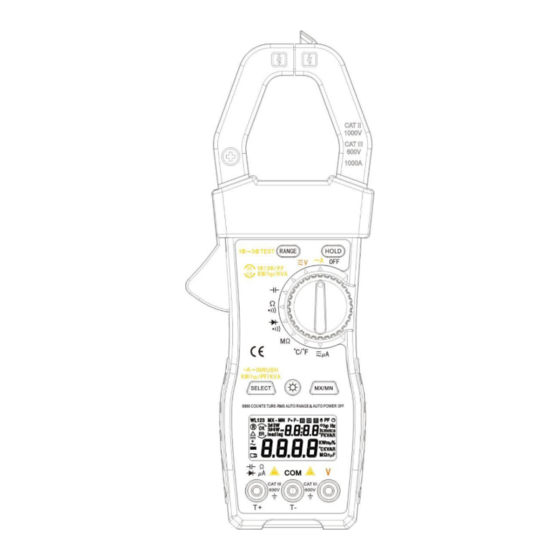
Page 9: Parts And Controls
2.5.17 3φPhase Sequence Indication: Overload Range Frequency Response Protection 80V to 480V 50Hz/60Hz 600V Note: the voltage input impedance of power measurement is 3M Ω 3. PARTS & CONTROLS 3.1 Description of Parts & Controls... - Page 10 3.1.1 "Range" button (1 in Figure 1): A. In "V" , ACA , "µA", capacitance and resistance function : (1) Press the "RANGE" key to enter the manual range and shows "®" mark on LCD 。 (2) Press the "RANGE" key again to select the desired range. (3) Press the "RANGE"...
- Page 11 / PF, kW / kvar, KVA / 0 and A + V. D. In the ℃/℉ function, press this key to select the measurement of Celsius or Fahrenheit. 3.1-5 Backlight button (5 in Figure 1) 3.1-6 "MX / Mn" maximum and minimum measurement keys (6 in Figure 1): (1) Select the desired ACA, ACV, DCV, ℃...
- Page 12 Connect the red test lead to the positive input for voltage and power measurements. 3.1-10 " " Jack (Figure 10): Connect the red test lead to this jack, which can be used to measure capacitance, resistance, diode, continuity and micro ampere measurement. As the positive terminal, it is the positive input of temperature test probe.
- Page 13 range. Read the current and frequency values displayed on the LCD. NOTE The current frequency measurement sensitivity is 8A and the frequency range is 40 ~ 400 Hz. If the frequency is less than 40Hz, the LCD displays "0.000Hz". disappeared 4.3 Inrush AC Current Measurement 1.
- Page 14 4. Connect the red lead V to the power line and clamp the same wire connected to the V (red) terminal. 5. The power clamp meter automatically selects the appropriate range. 6. Read the watt and HP values displayed on the LCD. 7.
- Page 15 4.5 3 Φ 3W AC Power KW, HP , KVA, KVAR, PF (Power Factor) and θ (Phase Angle) Measurement First, measure W (L1L2) (see Figure 3) 1. Set the rotary switch to the "KW / KVA" position 2. Press the "RANGE" key to select "3Φ3W" mode. 3.
- Page 16 Second: measure W (L2L3) (see Figure 4) 1. Disconnect the red test probe from the phase line of the jaw in the previous measurement. 2. Connect the test probe to the third phase line (e.g. B or L3). 3. Clamp the clamp on the third phase line (e.g. B or L3).
- Page 17 If you want to read the details of the recorded single data, press the "HOLD" key to select the required W or W display, and then press the "RANGE" L123 key (L12 and L23) to select KW + HP, KW + PF, KW + KVAR and KVA θ+ ,...
- Page 18 4.6 3Φ4W AC Power KW, HP, KVA, KVAR, PF (Power Factor) and θ (Phase Angle) Measurement First, measure WR (L1) (see Figure 5) 1. Set the rotary switch to the "KW / KVA" position 2. Press the "RANGE" key to select "3 Φ 4W "mode. 3.
- Page 19 Second, measure W (refer to figure 6) Y(L2) 1. Disconnect the test probe connected to the V (red) terminal from the phase line of the previous clamp. 2. Connect the test probe connected to the V (red) terminal to the second phase line (such as y or L2). 3.
- Page 20 clamp in the previous step. 2. Connect the test probe connected to the V (red) terminal to the third phase (e.g. B or L3). 3. clamp the phase line connected to the test probe (e.g. phase B or L3). 4. the instrument will automatically select the appropriate range.
- Page 21 If willing to read the details of that singly data recorded, press " HOLD " key to select desired W display then press "RANGE" key to select KW+HP, L123 KW+PF, KW+KVAR, KVA+θ for (L1, L2, L3) & KVA+PF for (L123) or A+V. 3 Φ...
- Page 22 Jack to B or L3 phase line, and connect the red probe test end connected to "V" Jack to R or L1 phase line (refer to figure 10) 5. The screen displays the voltage value. If the voltage is less than 80V, the "Err" symbol will be displayed; if the voltage is normal, the buzzer will sound once;...
- Page 23 black test lead to the negative side of the capacitor being tested. 5. Read capacitance value on LCD. 4.10 Diode & Continuity Measurement 1. Set the rotary switch to the " "range. 2. Insert the test leads into the input jack. (Black to COM and Red to )....
- Page 24 will be disabled. The auto power off mark" " will disappear. Auto power off mode is enabled each time you turn on the meter and is automatically disabled in the "MX / MN" mode. BATTERV REPLACEMENT WARNING To prevent electrical hazard or shock, turh off clamp meter and disconnect test leads before removing back covet.
Need help?
Do you have a question about the 580P and is the answer not in the manual?
Questions and answers