
Related Manuals for Miller CE


Summary of Contents for Miller CE
- Page 1 OM-286308B 2021-08 OM-286308A 2021-01 Wireless Remote Controls Wireless Remote Controls CE OWNER’S MANUAL For product information, Owner’s Manual translations, and more, visit www.MillerWelds.com...
- Page 2 We know you don’t have time to do it any other way. That’s why when Niels Miller first started building arc welders in 1929, he made sure his products offered long-lasting value and superior quality.
-
Page 3: Table Of Contents
TABLE OF CONTENTS SECTION 1 – SAFETY PRECAUTIONS – READ BEFORE USING..............1 Symbol Usage . - Page 5 DECLARATION OF CONFORMITY For European Community (CE marked) products. MILLER Electric Mfg. LLC, 1635 West Spencer Street, Appleton, WI 54914 U.S.A. declares that the product(s) identified in this declaration conform to the essential requirements and provisions of the stated Council Directives(s), Commission Regulation(s) and Standard(s).
- Page 6 DECLARATION OF CONFORMITY For United Kingdom (UKCA marked) products. MILLER Electric Mfg. LLC, 1635 West Spencer Street, Appleton, WI 54914 U.S.A. declares that the product(s) identified in this declaration conform to the essential requirements and provisions of the stated Regulation(s) and Standard(s).
-
Page 7: Section 1 - Safety Precautions - Read Before Using
SECTION 1 – SAFETY PRECAUTIONS – READ BEFORE USING Protect yourself and others from injury—read, follow, and save these important safety precautions and operating instructions. 1-1. Symbol Usage DANGER! – Indicates a hazardous situation which, if not avoided, will result in death or serious injury. The possible hazards are shown in the adjoining symbols or explained in the text. - Page 8 HOT PARTS can burn. WELDING can cause fire or explosion. � Do not touch hot parts bare handed. � Allow cooling period before working on equipment. Welding on closed containers, such as tanks, drums, or pipes, can cause them to blow up. �...
-
Page 9: Additional Hazards For Installation, Operation, And Maintenance
� Never weld on a pressurized cylinder — explosion will result. CYLINDERS can explode if � Use only correct compressed gas cylinders, regulators, hoses, damaged. and fittings designed for the specific application; maintain them Compressed gas cylinders contain gas under high and associated parts in good condition. -
Page 10: California Proposition 65 Warnings
� Have the installation regularly checked and maintained. � Be sure all equipment in the welding area is electromagnetically compatible. � Keep high-frequency source doors and panels tightly shut, keep spark gaps at correct setting, and use grounding and shielding to �... -
Page 11: Section 2 - Safety Precautions - Read Before Using
SECTION 2 – SAFETY PRECAUTIONS – READ BEFORE USING Protect yourself and others from injury—read, follow, and save these important safety precautions and operating instructions. 2-1. Symbol Usage DANGER! – Indicates a hazardous situation which, if not avoided, will result in death or serious injury. The possible hazards are shown in the adjoining symbols or explained in the text. -
Page 12: California Proposition 65 Warnings
2-3. California Proposition 65 Warnings WARNING – Cancer and Reproductive Harm — www. P65Warnings.ca.gov. 2-4. Principal Safety Standards Safety in Welding, Cutting, and Allied Processes, American Welding Safe Practice For Occupational And Educational Eye And Face Pro- Society standard ANSI Standard Z49.1. Website: http://www.aws.org. tection, ANSI Standard Z87.1, from American National Standards In- stitute. -
Page 13: Section 3 - Consignes De Sécurité - Lire Avant Utilisation
� Ne pas enrouler les câbles autour du corps. � S’isoler de la pièce à couper et du sol en utilisant des housses ou � Si la pièce soudée doit être mise à la terre, le faire directement des tapis assez grands afin d’éviter tout contact physique avec la... - Page 14 à souder ou la table de travail, le plus près possible de la soudure. LES ACCUMULATIONS DE GAZ � Isoler la pince de masse quand pas mis à la pièce pour éviter le risquent de provoquer des blessures contact avec tout objet métallique.
-
Page 15: Symboles De Dangers Supplémentaires En Relation Avec L'installation, Le Fonctionnement Et La Maintenance
� Brancher le câble de masse sur la pièce le plus près possible de la zone de soudage pour éviter le transport du courant sur une lon- LES BOUTEILLES peuvent exploser gue distance par des chemins inconnus éventuels en provoquant... - Page 16 � Veiller à souder à une distance de 100 mètres de tout équipement usage. électronique sensible. � Veiller à ce que ce poste de soudage soit posé et mis à la terre Les PIÈCES MOBILES peuvent conformément à ce mode d’emploi.
-
Page 17: Proposition Californienne 65 Avertissements
électromagnétique (CEM) 5. Connecter la pince sur la pièce aussi près que possible de la autour du circuit de soudage. Les champs électromagnétiques pro- soudure. -
Page 18: Section 4 - Consignes De Sécurité - Lire Avant Utilisation
Indique une situation dangereuse qui si on l’évite pas peut Ce groupe de symboles veut dire Avertissement! Attention! DAN- donner la mort ou des blessures graves. Les dangers pos- GER DE CHOC ELECTRIQUE, PIECES EN MOUVEMENT, et PIE- sibles sont montrés par les symboles joints ou sont expli-... -
Page 19: Proposition Californienne 65 Avertissements
4-3. Proposition californienne 65 Avertissements AVERTISSEMENT – Cancer et troubles de la reproduction — www.P65Warnings.ca.gov. 4-4. Principales normes de sécurité Safety in Welding, Cutting, and Allied Processes, American Welding Safe Practice For Occupational And Educational Eye And Face Pro- Society standard ANSI Standard Z49.1. Website: http://www.aws.org. tection, ANSI Standard Z87.1, from American National Standards In- stitute. -
Page 20: Section 5 - Specifications
Information About Default Weld Parameters And Settings NOTICE – Each welding application is unique. Although certain Miller Electric products are designed to determine and default to certain typical welding parameters and settings based upon specific and relatively limited application variables input by the end user, such default settings are for reference purposes only;... -
Page 21: Specifications
Canada IC 24958-301583 5123A-BGM13P 5123A-BGM13P Some symbols are found only on CE products. 5123A-MGM13P 5123A-MGM13P Not all applications are suitable for wireless communication. Rated range is approximate, and may vary depending on factors such as ob- structions, frequency interference, transmission technology, and weather. The figures listed assumes ideal conditions are present. -
Page 22: Section 6 - Installation
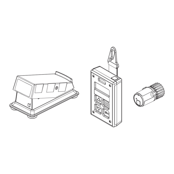
� Complete Parts List is available at www.MillerWelds.com SECTION 6 – INSTALLATION 5-7. Introduction 6-1. Introduction A wireless remote-control system consists of a control and transceiver. A wireless remote-control system consists of Wireless Foot Control a control and transceiver. Wireless Hand Control 1 Wireless Foot Control 14-Pin Transceiver The Wireless Foot Control, Wireless Hand Control, and... -
Page 23: Battery Installation
� Complete Parts List is available at www.MillerWelds.com 6-2. Battery Installation 1 AA Batteries Install four AA Batteries in shown orientation. 2 Wireless Hand Control Remove the accessory strap/magnet. Lift the bail on the on the 1/4 turn captive panel fastener. Rotate the bail of the 1/4 turn fastener counterclockwise. -
Page 24: Connecting 14-Pin Transceiver To Remote Receptacle
� Complete Parts List is available at www.MillerWelds.com 5-9. Connecting 14-Pin Transceiver To Remote 14 Receptacle 6-3. Connecting 14-Pin Transceiver To Remote Receptacle Unexpected weld output can cause electrical shock. Re- mote controls can turn on weld output from distant lo- cations. -
Page 25: Section 7 - Operation
Ref. 804746-B / Ref. 805627-A SECTION 7 – OPERATION 10. Wireless Foot Control Operation Unexpected weld output can 7-1. Wireless Foot Control Operation cause electrical shock. Wire- less remote controls can turn weld output on from distant locations. Disconnect receiv- er from remote 14 receptacle and remove battery from re- mote control before servicing... -
Page 26: Wireless Hand Control Operation
Unexpected weld output can cause electrical shock. Wireless remote controls can turn weld out- put on from distant locations. Dis- 7-2. Wireless Hand Control Operation connect 14-pin transceiver from remote 14 receptacle and remove the batteries from the wireless foot control and/or wireless hand control before servicing equip- ment. -
Page 27: Remote Amperage Or Voltage Control For Welding Power Source With Output Always On
5-12. Remote Amperage Or Voltage Control For Welding Power Source With Output Always On 7-3. Remote Amperage Or Voltage Control For Welding Power Source With Output Wireless hand control operation for weld- ing power sources with output contactor Always On always on (Stick, TIG, and voltage sensing wire feed welding). -
Page 28: Remote Amperage Or Voltage Control For Welding Power Source With Output Contactor
5-12. Remote Amperage Or Voltage Control For Welding Power Source With Output Always On 7-4. Remote Amperage Or Voltage Control For Welding Power Source With Output Wireless hand control operation for weld- ing power sources with output contactor Contactor always on (Stick, TIG, and voltage sensing wire feed welding). -
Page 29: Pairing A Wireless Hand Control With A 14-Pin Transceiver
7-5. Pairing A Wireless Hand Control With A 14-Pin Transceiver Wireless hand control operation for weld- ing power sources with output contactor always on (Stick, TIG, and voltage sens- ing wire feed welding). Unexpected weld output can cause electrical shock. Wireless remote controls can turn on weld output from distant locations. -
Page 30: Pairing A Wireless Foot Control With A 14-Pin Transceiver
7-6. Pairing A Wireless Foot Control With A 14-Pin Transceiver Wireless hand control operation for weld- ing power sources with output contactor always on (Stick, TIG, and voltage sens- ing wire feed welding). Unexpected weld output can cause electrical shock. Wireless remote controls can turn on weld output from distant locations. -
Page 31: Enabling Wireless Operation In Big 40 C, Big Blue 400/500/Air Pack/Turbo
7-7. Enabling Wireless Operation in Big 40 C, Big Blue 400/500/Air Pack/Turbo Wireless hand control operation for weld- ing power sources with output contactor always on (Stick, TIG, and voltage sens- ing wire feed welding). Stop engine. Disconnect negative (-) battery cable. Remove right side generator panel. -
Page 32: Transceiver 14-Pin Information
7-8. Transceiver 14-Pin Information 5-17. Transceiver 14-Pin Information Remote 14 Socket Socket Information Pin* Pin Information Contactor control +15 volts DC / 24 volts AC, referenced to G. Output Enable Contactor control +15 volts DC / 24 volts AC, ref- Contact closure to A completes and enables erenced to G. -
Page 33: Section 8 - Troubleshooting
SECTION 8 – TROUBLESHOOTING 8-1. Troubleshooting Table Trouble Remedy Remote completely inoperative. Red Make sure power source is on. wireless status light not lit on transceiver. Make sure receiver is connected properly to welding power source. (see Section 6-3). Red wireless status light is on, but no Check and if necessary, replace batteries in remote hand or foot control. -
Page 34: Section 9 - Parts List
SECTION 9 – PARTS LIST SECTION 7 PARTS LIST 9-1. Parts List Ref. 805625-A Figure 7-1. Wireless Foot Control Figure 9-1. Wireless Foot Control Item Dia. Part Mkgs. Description Quantity Wireless Foot Control (P/N 285008) 285008 Wireless Foot Control Item No. Part No. - Page 35 Ref. 805626-A Figure 9-2. Wireless Hand Control Wireless Hand Control (P/N 285358) Item No. Part No. Description Quantity 285341 Strap, Clip Assy (Includes) Clip, Belt Pad, Silicone 1.000 x 1.000 x .062 Thk Magnet, 1.00 Dia x .125 Thk Pin, Retaining .125 Od x 1.250 Lg Strap, Snap Hook Assy Clip, Belt Retainer 285350...
- Page 36 Notes...
- Page 37 Notes...
- Page 38 Notes...
-
Page 39: Warranty
Effective January 1, 2021 (Equipment with a serial number preface of NB or newer) This limited warranty supersedes all previous Miller warranties and is exclusive with no other guarantees or warranties expressed or implied. LIMITED WARRANTY − Subject to the terms and conditions TIG Torches (No Labor) below, Miller Electric Mfg. - Page 40 Appleton, WI 54914 USA tact your distributor and/or equipment manu- facturer’s Transportation Department. International Headquarters–USA USA Phone: 920-735-4505 USA & Canada FAX: 920-735-4134 International FAX: 920-735-4125 For International Locations Visit www.MillerWelds.com ORIGINAL INSTRUCTIONS – PRINTED IN USA © Miller Electric Mfg. LLC 2021-08...
Need help?
Do you have a question about the CE and is the answer not in the manual?
Questions and answers