Table of Contents
Advertisement
Quick Links
Read and follow these instructions and all
safety blocks carefully.
Have only trained and qualified persons
install, operate, or service this unit.
Call your distributor if you do not understand
the directions.
cover 8/92 − Ref. ST-141 127-A
OWNER'S
MANUAL
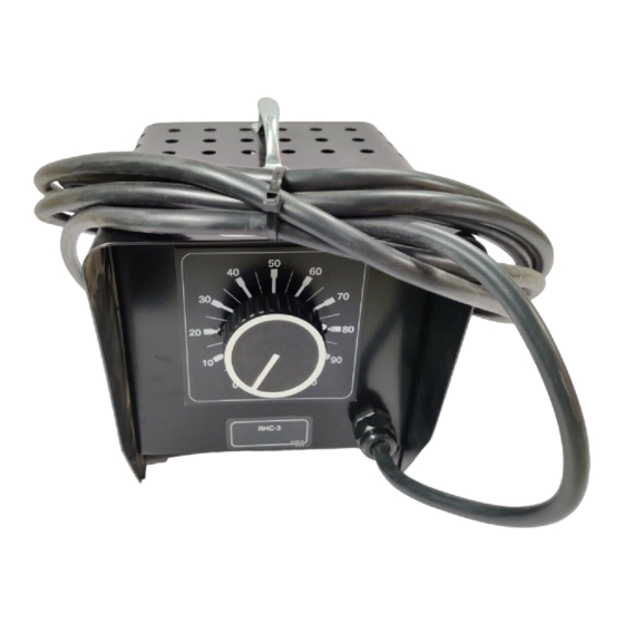
RHC-3, RHC-3-2, RHC-3GD25B,
RHCS-3, RHC-3-GD34A, RHC-14,
And RHC-23
Remote Hand Controls
For Remote Amperage Or Voltage Control
RHC-14 And RHC-23 Models Add Output (Contactor) Control
Primarily For SMAW Welding
20 ft (6 m) Interconnecting Cord
May 1993
Form: OM-823H
Effective With Serial No. KB055102
Give this manual to the operator.
For help, call your distributor
or: MILLER ELECTRIC Mfg. Co., P.O. Box
1079, Appleton, WI 54912
414-734-9821
PRINTED IN USA
Advertisement
Table of Contents

Subscribe to Our Youtube Channel
Related Manuals for Miller RHC-3


Summary of Contents for Miller RHC-3
- Page 1 Have only trained and qualified persons For help, call your distributor install, operate, or service this unit. Call your distributor if you do not understand or: MILLER ELECTRIC Mfg. Co., P.O. Box the directions. 1079, Appleton, WI 54912 414-734-9821 cover 8/92 − Ref. ST-141 127-A...
-
Page 3: Table Of Contents
SECTION 7 − PARTS LIST Figure 7-1. Complete Assembly (RHC-3 Illustrated) ........ -
Page 4: Section 1 − Safety Information
SECTION 1 − SAFETY INFORMATION mod1.1 2/93 Read all safety messages throughout this manual. Obey all safety messages to avoid injury. Learn the meaning of WARNING and CAUTION. Safety Alert Symbol Signal Word WARNING means possible death or serious injury can happen. WARNING CAUTION CAUTION means possible minor... -
Page 5: Interconnections
3-2. Interconnections Turn Off welding power source, or stop engine on welding generator. Remote Hand Control Interconnecting Cord Units are equipped with a 20 ft m) multiconductor cord (unless otherwise specified). If a longer cord is required, see Table 3-1. Twistlock Plug Make connection to matching re- ceptacle on welding power source... -
Page 6: Control Operation
4-1. Control Operation NOTE See welding power source or welding generator Owner’s Manual to determine if Remote Hand Control will act as a fine Amperage or Voltage control, or as a full range Amperage or Voltage control. A. Adjusting Amperage Or Voltage Without Output (Contactor) Control EXAMPLE Of Fine Remote Amperage Control Without Output (Contactor) Control (40 A) (200 A) - Page 7 B. Adjusting Amperage Or Voltage With Output (Contactor) Control (RHC-14 And RHC-23 Models Only) WARNING ELECTRIC SHOCK can kill. • Do not touch live electrical parts. • Do not touch weld output terminals when contactor is energized. • Do not touch electrode and work clamp at the same time. swarn7.1 10/91 EXAMPLE Of Fine Remote Amperage Control With Output (Contactor) Control (5 A)
-
Page 8: Section 5 − Maintenance & Troubleshooting
C. Remote Hand Control Of Two Welding Power Sources Or Welding Generators Models with the suffix -2, are designed to control two identical welding power sources or welding generators at the same time. Turning the knob on the remote hand control adjusts the amperage or voltage on each welding power source or welding generator to the same output setting. -
Page 9: Section 6 − Electrical Diagrams
SECTION 6 − ELECTRICAL DIAGRAMS SA-150 670 Figure 6-1. Circuit Diagram For RHC-3 Ref. SA-150 671 Figure 6-2. Circuit Diagram For RHCS-3 OM-823 Page 6... - Page 10 SA-094 231-A Figure 6-3. Circuit Diagram For RHC-3-GD34A SA-094 232-A Figure 6-4. Circuit Diagram For RHC-3-GD25B SA-053 656-A Figure 6-5. Circuit Diagram For RHC-14 And RHC-23 OM-823 Page 7...
-
Page 11: Section 7 − Parts List
SECTION 7 − PARTS LIST ST-141 128 Figure 7-1. Complete Assembly (RHC-3 Illustrated) OM-823 Page 8... - Page 12 ..... . . +When ordering a component originally displaying a precautionary label, the label should also be ordered. BE SURE TO PROVIDE MODEL AND SERIAL NUMBER WHEN ORDERING REPLACEMENT PARTS. Quantity Model RHC-3-GD Item Dia. Part Mkgs.
Need help?
Do you have a question about the RHC-3 and is the answer not in the manual?
Questions and answers