Table of Contents
Advertisement
Quick Links
Advertisement
Table of Contents

Summary of Contents for RAYSTECH RT5120
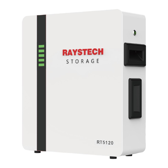
- Page 2 About this manual This manual is intended for the RT5120 Energy Storage battery.This batteries can be installed in Parallel and Series, pay more attention for the DIP setting and address selection. Statement Compliant to Best Practice Guide for Battery Storage Equipment—Electrical Safety.Requirements- version 1- Pre-assembled integrated battery energy storage system...
-
Page 3: Table Of Contents
3.2 Indicator and Ports ......................6 3.2.1 Indicator ........................6 3.2.2 Ports .......................... 6 3.2.3 Communication Interface..................7 3.3 Solution of RAYSTECH ....................10 3.4 Feature..........................11 4. Installation Prerequisites......................11 4.1 Installation Process ......................11 4.2 Installation Position ......................12 4.3 Tools............................ -
Page 4: Safety Introduction
1. Safety Introduction 1.1 Important Safety Instructions This manual contains important instructions for: RT5120 Energy Storage product and this manual must be followed when installing and using this product. This product is designed and tested in accordance with international safety requirements CE, but as with all electrical and electronic equipment, certain precautions must be observed when installing and / or operating the product. -
Page 5: Battery Handing Guide
⚫ The battery not be connected directly to SELV circuit. 1.4 Response to Emergency Situations The RAYSTECH battery is designed with multiple safety strategies to prevent hazards resulting from failures. However, RAYSTECH cannot guarantee their absolute safety for uncertain situations. -
Page 6: Wet Battery
If the battery catches fire, it will produce poisonous gases. Do not approach. 1.4.3 Wet battery If the battery is wet or submerged in water, do not try to access it. Contact RAYSTECH Customer Service or your distributor for technical assistance. -
Page 7: Scrap Battery
These products shall be handled with care and immediately inspected if visibly damaged. If the carton visibly damaged, please contact with RAYSTECH customer service to confirm whether the battery could be used safely or not. -
Page 8: Product Introduction
3. Product Introduction 3.1 Technical Specifications RT5120 Product Type Battery Capacity 50Ah+50Ah Max.recommended DOD 5.12kW Max Charge Power 7.68kW Max Disharge Power 48~56Vd.c Voltage 51.2Vd.c Nominal Voltage Nominal Charging Current 100A Nominal Discharging Current 100A Max Charging Current 150A (1.5c) Max Discharging Current 55.6Vd.c... -
Page 9: Indicator And Ports
3.2 Indicator and Ports 3.2.1 Indicator There are LED indicators on the front of the battery to show its operating status. Item Designation Definition Showing the SOC of battery 3.2.2 Ports The power cable interface and communication cable interface. -
Page 10: Communication Interface
3.2.3 Communication Interface Designation Definition M/S IN Communication between batteries-‘in’port M/S OUT Communication between batteries-‘out’port Inverter Communication between master battery and inverter... - Page 11 The communication cables of battery and inverter is showing as below:...
- Page 12 Items Inverters SOFAR SOLIS GOODWE LUXPOWER(TEK) INVT MAGAREVO DEYE Thinkpower 4H5L Sermatec Growatt Afore Solinteg Sol-ark AISWEI LuxPower(Old) 4H3L Voltronic RS485 5A3B EPEVER...
-
Page 13: Solution Of Raystech
3.3 Solution of RAYSTECH... -
Page 14: Feature
3.4 Feature The RAYSTECH Energy Storage battery has following features: ⚫ Energy storage unit This battery is suit for photovoltaic system compatibility. ⚫ Battery management system (BMS) The battery built-in BMS monitors its operation and prevents the battery from operating outside design limitations. -
Page 15: Installation Position
4.2 Installation Position Make sure that the installation position meets the following conditions: ⚫ The building is designed to withstand earthquakes. ⚫ Far away from the sea to avoid salt water and humidity. ⚫ The floor is flat and level. ⚫... -
Page 16: Safety Instruments
4.4 Safety Instruments When dealing with the battery, following safety gears should be equipped. Installers must meet the relevant requirements or the domestic legislation and other relevant international standards. Insulated glove Safety goggles Safety shoes 4.5 Storage If the battery is not to be installed immediately, and needs to be stored for a long period, please choose an appropriate location to store it. -
Page 17: Battery Installation
5. Battery Installation 5.1 Checks before Installation There are few things to check before installing the battery to ensure that it has no defects. ⚫ Check the battery voltage using following instruction. ⚫ Press and hold the panel button for 4s and release after two indicators turn on. ⚫... -
Page 18: Wall Mounting
2. Connecting the ground cables 5.2.2 Wall Mounting 1.Drill holes of M6 in the wall according to 2.Install the screws of M6 between the the distance of the holes in the bracket. bracket and the battery 3.3.Putting the battery on the bracket,and 4.Connecting the ground cables. -
Page 19: Cable Connections Of The Battery
5.3 Cable Connections of the Battery WARNING Connect cables in accordance with local installation laws and regulations. Before connecting cables, ensure that the battery is OFF. Otherwise, the high voltage of the battery may result in electric shocks. 5.3.1 Parallel Connection NOTICE Before two or more batteries installed in parallel, please check the voltage of each battery and make sure the voltage difference less than 2.0V. - Page 20 * Wall mounting 1. Two batteries installed. 2. Four batteries installed. NOTICE For wall mounting, the number of batteries should be less than 4. If more batteries are installed, a cabinet is recommended to use.
-
Page 21: Commissioning
6.Commissioning 6.1 Commissioning Battery If only one battery is installed, use the following steps to put it in operation: 1 Press the button on the upper side of the unit until the indicator lights on. 2 Make sure the Run light is on. If it stays off, do not use the battery and contact customer service. -
Page 22: Firmware Update
6.3 Inverter Communication Settings The different inverter communication settings are given below. Inverter brand Inverter Protocol Inverter Remark type type Battery settings Low Voltage Lithium Protocol= Default Low Voltage Lithium Protocol =0 Low Voltage Lithium Protocol= 7 Low Voltage Lithium Protocol= L51 Low Voltage Lithium...

Need help?
Do you have a question about the RT5120 and is the answer not in the manual?
Questions and answers