Table of Contents
Advertisement
Quick Links
Advertisement
Table of Contents

Related Manuals for Organomation MICROVAP 11801


Summary of Contents for Organomation MICROVAP 11801
- Page 1 ® Organomation ® MICROVAP Nitrogen Evaporation System Models 11801 (Single Plate) 11806 (6 Position) 11815 (15 Position) 11824 (24 Position) INSTRUCTION MANUAL 266 RIVER ROAD WEST BERLIN, MA 01503 U. S. A. Tel: 888-838-7300 Fax: 978-838-2786 Email: sales@organomation.com...
-
Page 3: Table Of Contents
® MICROVAP TABLE OF CONTENTS Introduction Instrument Items Shipped ………………………………………….. Instrument Description ……………………………..……………… Safety Considerations - Read before operation ………………………… Installation Part Identification ………………………………………………….. Assembly Instructions……………………………………………… Location…………………………………………………..………… Operation Planning and Preparation …………………………………………... Bath Controls Diagram …………………………………………….. Bath Operation …………………………………………………….. Instrument Controls Diagram ……………………………………… Instrument Operation ………………………………………………. - Page 4 Retain all cartons and packaging materials until all components have been checked against the packing slip, the component list below, and the equipment has been assembled and tested. Contact Organomation immediately if any damage or discrepancies are found.
-
Page 5: Introduction
® MICROVAP INTRODUCTION Option Codes and additional items shipped The following list contains option codes and items which may have been shipped in conjunction with the standard parts shown on the previous page. Please check your packing list and order information carefully to determine if these items are included in your shipment. For a complete list of available accessories, please refer to the Accessories Section. -
Page 6: Instrument Description
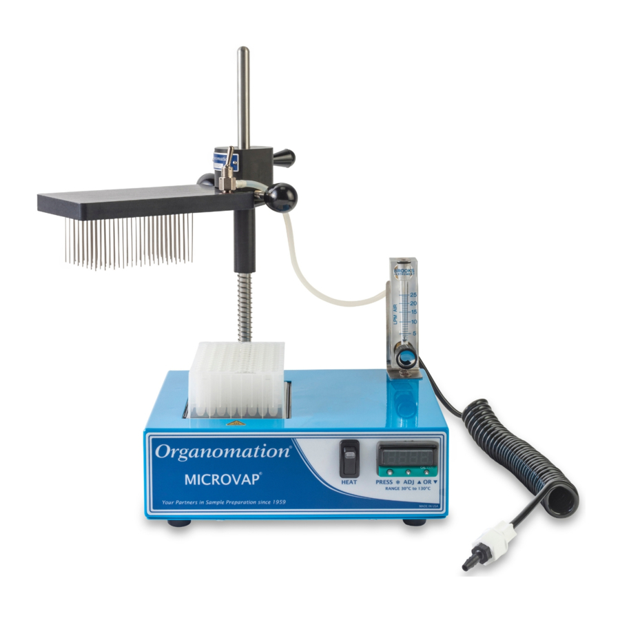
® MICROVAP INTRODUCTION Instrument Description The MICROVAP Nitrogen Evaporation System is designed for general evaporation and / or concentration of analytical or biological samples in 96 well micro plates or sample tubes under controlled and reproducible conditions. Other micro well plate configurations are available. - Page 7 This equipment should not be modified or altered. Organomation assumes no liability for any misuse of or modification to this product and such misuse or modification will immediately void all warranties.
- Page 8 10. The main safety disconnect for the instrument is the disconnect of the main power cord from the power supply. Ensure the instrument is posi- tioned in a way that this can be accessed safely. 11. Use only power supply cord set provided by Organomation with this product V24.2...
-
Page 9: Installation
® MICROVAP INSTALLATION Assembly Instructions: Single Plate; 6, 15 & 24 POSITION MICROVAP Gather and identify all components. Heating Unit Manifold Thumb Screws Stainless Steel Rod Accessory Thumb Screw Compression Spring Hex Key [ 1/8” ] Instrument Manifold Flowmeter Bracket Heat Block Flowmeter Offset Collar... - Page 10 ® MICROVAP INSTALLATION Assembly Instructions: Single Plate; 6, 15 & 24 POSITION MICROVAP Position heating unit [A] on a flat surface. Remove screws from rear top surface. Position flowmeter bracket [J] over holes as shown. Replace screws. Remove screws from rear of flowmeter [K] Position flowmeter over bracket holes as shown.
- Page 11 ® MICROVAP INSTALLATION Assembly Instructions: Single Plate; 6, 15 & 24 POSITION MICROVAP Use the 1/8” hex key [I] to loosen set screw on rear block. Insert the stainless steel rod [B] into the block with the ball end facing up. Center the alignment groove on the rod to the back face of the rear mounting block, facing away from the heating...
- Page 12 ® MICROVAP INSTALLATION Assembly Instructions: Single Plate; 6, 15 & 24 POSITION MICROVAP Screw the manifold thumb screws [G] into the sides of the instrument manifold [D]. Screw the accessory thumb screw [H] into the upper back of the instrument manifold.
- Page 13 ® MICROVAP INSTALLATION Assembly Instructions: Single Plate; 6, 15 & 24 POSITION MICROVAP Attach the exposed end of the filter, in the coiled connector tube assembly [L], to the lower rear fitting of the flowmeter. Attach the other end of the connector tube to a suitable gas source (10-30 PSIG).
- Page 14 ® MICROVAP INSTALLATION Assembly Instructions: Single Plate; 6, 15 & 24 POSITION MICROVAP Use the accessory thumb screw [H] for easier removal of the heat block. V24.2 - 14 -...
-
Page 15: Location
® MICROVAP INSTALLATION Location The MICROVAP Evaporator System should only be used in a chemical fume hood with adequate ventilation. The location should provide the necessary support services for the instrument. These include electrical power (required for heat unit) and a clean inert gas source (Air or Nitrogen). -
Page 16: Planning And Preparation
96 position deep well plates may also be used. Other well plates of different capacities can also be accommodated, consult Organomation for details. The MICROVAP System is manufactured utilizing inert materials. The white translucent and black coiled tubing used is free of phthalate presence. -
Page 17: Bath Controls Diagram
® MICROVAP OPERATION Bath Controls Diagram Picture Description Function Main Power Switch Turns power to the unit on and off Digital Temperature Adjusts the bath temperature Controller Indicates heating when heaters are energized, will Amber Light(s) cycle at temperature Black Rocker Switch Heater power to samples Fuse Holder Protects the system from hazardous voltages... - Page 18 ® MICROVAP OPERATION Digital Temperature Controller Diagram Picture Description Function Shows process value (PV), set value (SV), or parameter Display names and values Blinks when auto-tuning or self-tuning operations are run- Tuning Lamp ning Arrow Key(s) Used to change parameter values Used to switch between PV and SV display.
-
Page 19: Bath Operation
® MICROVAP OPERATION Bath Operation Turn the main power switch [A] on. *The illuminated portion should glow. Digital Temperature Controller [B]: Adjust the digital controller to the desired temperature set point. To view the current set point: press the SEL key. Press again to return. To change the current set point (∆T): press the SEL key and then press either the ▲... - Page 20 ® MICROVAP OPERATION Bath Operation Single Block MICROVAP Press the black rocker switch [D] upwards to power the heaters on. *Older models may not have idle switch option V24.2 - 20 -...
-
Page 21: Instrument Controls Diagram
® MICROVAP OPERATION Instrument Controls Diagram: Single Plate, 6, 15 & 24 POSITION MICROVAP Picture ID Description Function Thumb Knobs Locks manifold position when tightened Manifold Gas Valve Open or close gas flow to distribution manifold Offset Collar Alters stopping height for manifold Heat Block Medium for heating samples Flow Meter Valve... - Page 22 ® MICROVAP OPERATION Instrument Operation: Single Plate, 6, 15 & 24 POSITION MICROVAP Preheat the heat block. Swing the manifold away. Place the well plate, or sample tubes, in the heat block. V24.2 - 22 -...
- Page 23 ® MICROVAP OPERATION Instrument Operation: Single Plate, 6, 15 & 24 POSITION MICROVAP Re-center your manifold above the samples. An audible sound will indicate that the manifold is positioned in the alignment groove of the rod. Loosen the offset collar thumb knob [G] Loosen the manifold thumb knobs [E] to adjust the stopping height of the to adjust the instrument manifold...
- Page 24 ® MICROVAP OPERATION Instrument Operation: Single Plate, 6, 15 & 24 POSITION MICROVAP (a) Flip the manifold gas valve on. (b) Turn the flow meter valve off. (c) Turn on the gas supply to the MICROVAP. Using the flow meter valve: Slowly increase the gas flow until a visible dimple...
-
Page 25: Instrument Operation
® MICROVAP OPERATION Instrument Operation (Post-Evaporation): Single Plate, 6, 15 & 24 POSITION MICROVAP Evaporate as necessary. Turn off the manifold gas valve. Swing the manifold away. Remove plate or samples. V24.2 - 25 -... -
Page 26: Maintenance And Cleaning
If in doubt, contact Organomation. Acidic Environment - When in contact with or exposed to acidic materials, vapors, or samples. -
Page 27: Fuse Replacement
® MICROVAP MAINTENANCE Fuse Replacement Use only exact replacement fuses. Incorrect fuses create a potential fire hazard and personal injury Turn off the system and disconnect the power cord Push and turn the knurled fuse holder counterclockwise until the holder pops Replace the old fuse Put the fuse holder back in by aligning the keys, pushing it in, and turning it... - Page 28 ® MICROVAP TROUBLESHOOTING SYMPTOMS CAUSES SOLUTIONS No Power to unit. Electrical outlet not energized. Energize electrical outlet. Unit power cord not plugged in. Plug in bath power cord. Blown fuse Replace the fuse, contact factory for instructions Internal electrical fault. Contact factory for instructions.
- Page 29 ® MICROVAP TROUBLESHOOTING Calibration of PXR3 Digital Temperature Controller If the controller and heat block temperature readings are different, then the Digital Temperature Controller will require calibration. The controller readings can be adjusted using both one-point calibration or re-tuning the process parameters. Calibration at the temperature used most fre- quently will yield the most accurate results.
- Page 30 ® MICROVAP TROUBLESHOOTING Calibration of PXR3 Digital Temperature Controller One-Point Calibration (Cont.) Once the temperature discrepancy has been determined, press and hold for 3 seconds until the screen reads Push until the screen reads Press and the current value will be displayed. Press to adjust to the calculated discrepancy.
- Page 31 ® MICROVAP TROUBLESHOOTING Calibration of PXR3 Digital Temperature Controller Overshoot Control (FUZY) The temperature controller may fluctuate around the set point temperature in certain applica- tions. To minimize fluctuations and prevent overshoot, change the controller to use fuzzy con- trol: Press and hold for 3 seconds until the screen reads Push...
- Page 32 ® MICROVAP TROUBLESHOOTING Calibration of PXR3 Digital Temperature Controller Re-Tuning Application (SELF) The temperature controller is tuned with the included sample block. If the default operating pa- rameters are causing issues, then the controller should be re-tuned for the application. Self tun- ing is recommended as a first troubleshooting step when experiencing insufficient performance with temperature control: Press...
- Page 33 ® MICROVAP TROUBLESHOOTING Calibration of PXR3 Digital Temperature Controller Re-Tuning Application (Cont.) Press again to return to the process value display. Turn off the heat. Wait for the tempera- ture to fall and/or stabilize. Turn the device off, then on again. Turn on the heat The tuning lamp will flicker until the new parameters are established...
- Page 34 ® MICROVAP TROUBLESHOOTING Calibration of PXR3 Digital Temperature Controller Auto-Tuning Application Auto tuning is used to find the optimal PID parameters for the application. The process can take several hours to complete and temperatures may significantly fluctuate while calibration is un- derway.
- Page 35 ® MICROVAP TROUBLESHOOTING Calibration of PXR3 Digital Temperature Controller Auto-Tuning Application (Cont.) Hold to return to the process value display. Turn on the heat The tuning lamp will flicker until the new parameters are established V24.2 - 35 -...
-
Page 36: Service And Returns
MICROVAP TECHNICAL INFORMATION Service and Returns In the event a product purchased from Organomation needs service or must be returned please follow the outlined procedures below. Contact Organomation Technical Support Department Before returning any product to Organomation for any reason, please contact the Technical Support Department, toll free at 888-838-7300 or email sales@organomation.com Support is available Monday through Friday from 8:30 AM... -
Page 37: Claims For Damage And Shortage
TECHNICAL INFORMATION Shipping - Claims for damage and shortage Organomation makes a sincere effort to ensure your purchase is properly packed and all items listed on the packing slip are in fact enclosed with the shipment. In the event that your purchase is damaged or if any items are missing, please follow the procedures below. - Page 38 ® MICROVAP TECHNICAL INFORMATION Specifications Electrical Requirements: 115 or 230 VAC ± 10% single phase, non switchable; 50 - 60 Hz. 3 wire grounded outlet required. Model 11801 1 Position unit 180 W Model 11806 6 Position unit 180 W Model 11815 15 Position unit 180 W Model 11824 24 Position unit 180 W Fuses:...
-
Page 39: Declaration Of Conformity
Organomation 266 River Road West Berlin, MA 01503 United States We, Organomation, declare under our sole responsibility that the following products Cat# 11801; MICROVAP for 96 well microplate, 230V Cat# 11801-RT; MICROVAP for 96 well microplate with acid resistant coating, 230V Cat# 11806;...
Need help?
Do you have a question about the MICROVAP 11801 and is the answer not in the manual?
Questions and answers