Table of Contents
Advertisement
Quick Links
Advertisement
Table of Contents

Related Manuals for Organomation MICROVAP 11801


Summary of Contents for Organomation MICROVAP 11801
- Page 1 ® MICROVAP Nitrogen Evaporation System Models 11801 (Single Plate) 11806 (6 Position) 11815 (15 Position) 11824 (24 Position) INSTRUCTION MANUAL 266 RIVER ROAD WEST BERLIN, MA 01503 U. S. A. Tel: 888-838-7300 Fax: 978-838-2786 Email: sales@organomation.com...
-
Page 3: Table Of Contents
® MICROVAP TABLE OF CONTENTS Introduction Instrument Items Shipped …………………………. Instrument Description ……………………………. Instrument Part Identification ……………………... Safety Considerations - Read before operation ………… Installation Location ……………………………………………. Bath Setup …………………………………………. Instrument Setup ………………………………….. . Operation Instrument Control Identification ………………….. Planning and Preparation …………………………... Bath Operation ……………………………………... - Page 4 Retain all cartons and packaging materials until all components have been checked against the packing slip, the component list below, and the equipment has been assembled and tested. Contact Organomation immediately if any damage or discrepancies are found.
-
Page 5: Introduction
® MICROVAP INTRODUCTION Option Codes and additional items shipped The following list contains option codes and items which may have been shipped in conjunction with the standard parts shown on the previous page. Please check your packing list and order information carefully to determine if these items are included in your shipment. For a complete list of available accessories, please refer to the Accessories Section. -
Page 6: Instrument Description
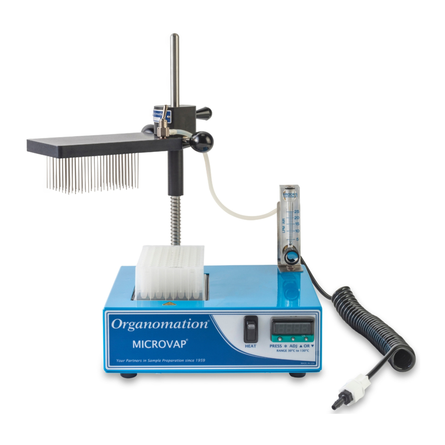
® MICROVAP INTRODUCTION Instrument Description The MICROVAP Nitrogen Evaporation System is designed for general evaporation and / or concentration of analytical or biological samples in 96 well titer plates or sample tubes under controlled and reproducible conditions. Other micro well plate configurations are available. - Page 7 This equipment should not be modified or altered. Organomation assumes no liability for any misuse of or modification to this product and such misuse or modification will immediately void all warranties.
-
Page 8: Installation
® MICROVAP INSTALLATION Assembly Instructions: Single Plate; 6, 15 & 24 POSITION MICROVAP Gather and identify all components. Heating Unit Manifold Thumb Screws Stainless Steel Rod Accessory Thumb Screw Compression Spring Hex Key [ 1/8” ] Instrument Manifold Flowmeter Bracket Heat Block Flowmeter Offset Collar... - Page 9 ® MICROVAP INSTALLATION Assembly Instructions: Single Plate; 6, 15 & 24 POSITION MICROVAP Position heating unit [A] on a flat surface. Remove screws from rear top surface. Position flowmeter bracket [J] over holes as shown. Replace screws. Remove screws from rear of flowmeter [K] Position flowmeter over bracket holes as shown.
- Page 10 ® MICROVAP INSTALLATION Assembly Instructions: Single Plate; 6, 15 & 24 POSITION MICROVAP Use the 1/8” hex key [I] to loosen set screw on rear block. Insert the stainless steel rod [B] into the block with the ball end facing up. Center the alignment groove on the rod to the back face of the rear mounting block, facing away from the heating...
- Page 11 ® MICROVAP INSTALLATION Assembly Instructions: Single Plate; 6, 15 & 24 POSITION MICROVAP Screw the manifold thumb screws [G] into the sides of the instrument manifold [D]. Screw the accessory thumb screw [H] into the upper back of the instrument manifold.
- Page 12 ® MICROVAP INSTALLATION Assembly Instructions: Single Plate; 6, 15 & 24 POSITION MICROVAP Attach the exposed end of the filter, in the coiled connector tube assembly [L], to the lower rear fitting of the flowmeter. Attach the other end of the connector tube to a suitable gas source (10-30 PSIG).
- Page 13 ® MICROVAP INSTALLATION Assembly Instructions: Single Plate; 6, 15 & 24 POSITION MICROVAP Use the accessory thumb screw [H] for easier removal of the heat block. V19.6 - 13 -...
-
Page 14: Location
® MICROVAP INSTALLATION Location The MICROVAP Evaporator System should be located on a bench top or in a chemical fume hood if hazardous or flammable materials and solvents are to be used. The location should provide the necessary support services for the instrument. These include electrical power (required for heat unit) and a clean inert gas source (Air or Nitrogen). -
Page 15: Planning And Preparation
96 position deep well plates may also be used. Other well plates of different capacities can also be accommodated, consult Organomation for details. The MICROVAP System is manufactured utilizing inert materials. The white translucent and black coiled tubing used is free of phthalate presence. - Page 16 ® MICROVAP OPERATION Bath Controls Diagram Picture ID Description Function Main Power Switch Turns power to the unit on and off Digital Temperature Controller Adjusts the bath temperature Amber Light(s) Indicates heating when heaters are energized, will cycle at temperature Black Rocker Switch Heater power to samples Front...
- Page 17 ® MICROVAP OPERATION Bath Preparation The single position MICROVAP is designed to accommodate sample arrays of 6, 15, 24, and 96 positions. Default program settings are dependent on the model purchased. It is important to verify that your CAL3300 Digital Temperature Controller is properly tuned for your application when switching between array configurations.
-
Page 18: Bath Operation
® MICROVAP OPERATION Bath Operation Turn the main power switch [A] on. *The illuminated portion should glow. Digital Temperature Controller [B]: Adjust the digital controller to the desired temperature set point. To view the current set point: ⁎ hold the key. - Page 19 ® MICROVAP OPERATION Bath Operation Single Block MICROVAP Press the black rocker switch [D] upwards to power the heaters on. *Older models may not have idle switch option V19.6 - 19 -...
- Page 20 ® MICROVAP OPERATION Instrument Controls Diagram: Single Plate, 6, 15 & 24 POSITION MICROVAP Picture ID Description Function Thumb Knobs Locks manifold position when tightened Manifold Gas Valve Open or close gas flow to distribution manifold Offset Collar Alters stopping height for manifold Heat Block Medium for heating samples Flow Meter Valve...
- Page 21 ® MICROVAP OPERATION Instrument Operation: Single Plate, 6, 15 & 24 POSITION MICROVAP Preheat the heat block. Swing the manifold away. Place the well plate, or sample tubes, in the heat block. V19.6 - 21 -...
- Page 22 ® MICROVAP OPERATION Instrument Operation: Single Plate, 6, 15 & 24 POSITION MICROVAP Re-center your manifold above the samples. An audible sound will indicate that the manifold is positioned in the alignment groove of the rod. Loosen the offset collar thumb knob [G] Loosen the manifold thumb knobs [E] to adjust the stopping height of the to adjust the instrument manifold...
- Page 23 ® MICROVAP OPERATION Instrument Operation: Single Plate, 6, 15 & 24 POSITION MICROVAP (a) Flip the manifold gas valve on. (b) Turn the flow meter valve off. (c) Turn on the gas supply to the MICROVAP. Using the flow meter valve: Slowly increase the gas flow until a visible dimple...
-
Page 24: Instrument Operation
® MICROVAP OPERATION Instrument Operation (Post-Evaporation): Single Plate, 6, 15 & 24 POSITION MICROVAP Evaporate as necessary. Turn off the manifold gas valve. Swing the manifold away. Remove plate or samples. V19.6 - 24 -... -
Page 25: Maintenance And Cleaning
® MICROVAP MAINTENANCE Maintenance and Cleaning The MICROVAP Evaporation system is manufactured from extremely durable materials and may last for years if operated and maintained properly. The following guidelines are recommended for use with MICROVAP systems. Cleaning - The metal components may be cleaned with a soft cloth or damp spong. -
Page 26: Troubleshooting
® MICROVAP TROUBLESHOOTING SYMPTOMS CAUSES SOLUTIONS No Power to unit. Electrical outlet not energized. Energize electrical outlet. Unit power cord not plugged in. Plug in bath power cord. Internal electrical fault. Contact factory for instructions. Bad wire connection. Bath will require service, contact Unit does not heat. - Page 27 ® MICROVAP TROUBLESHOOTING Calibration of CAL3300 Digital Thermometer If the controller and heat block temperature readings are different, then the CAL3300 Digital Thermometer will require calibration. The controller readings can be adjusted using both one- point and two-point calibration settings. Calibration at the temperature used most frequently will yield the most accurate results.
- Page 28 ® MICROVAP TROUBLESHOOTING One-Point Calibration (Continued) ⁎ 6. Hold and press ▲ or ▼ to adjust to the calculated discrepancy. Use ▼ for negative (-) values ● Use ▲ for positive ( ) values ● ⁎ 7. Once the correction has been entered, release 8.
- Page 29 ® MICROVAP TROUBLESHOOTING Two-Point Calibration (Continued) For example: Low End: Heat block reading (T ) = 43 °C Controller reading = 45 °C Error reading (E ) = (-) 2 °C High End: Heat block reading (T ) = 94 °C Controller reading = 100 °C Error reading (E ) = (-) 6 °C...
- Page 30 MICROVAP TECHNICAL INFORMATION Service and Returns In the event a product purchased from Organomation needs service or must be returned please follow the outlined procedures below. Contact Organomation Technical Support Department Before returning any product to Organomation Associates for any reason, please contact the Technical Support Department, toll free at 888-838-7300 or email sales@organomation.com Support is available Monday through Friday from 8:30 AM...
-
Page 31: Technical Information
Contact Organomation immediately at 888-838-7300 or sales@organomation.com If a damaged item needs to be replaced, Organomation will send this item under warranty at no charge. The damaged item must be returned to Organomation. Please follow the instructions listed in the Service and Returns section. Important - items not returned or which are further damaged or destroyed in transit are the responsibility of the customer and will be billable. -
Page 32: Specifications
® MICROVAP TECHNICAL INFORMATION Specifications 120 or 240 VAC single phase, non switchable, 50 - 60 Hz. Electrical Requirements: 3 wire grounded outlet required. Model 11801 1 Position unit 180 W Model 11806 6 Position unit 180 W Model 11815 15 Position unit 180 W Model 11824 24 Position unit 180 W Water Services Required: None.
Need help?
Do you have a question about the MICROVAP 11801 and is the answer not in the manual?
Questions and answers