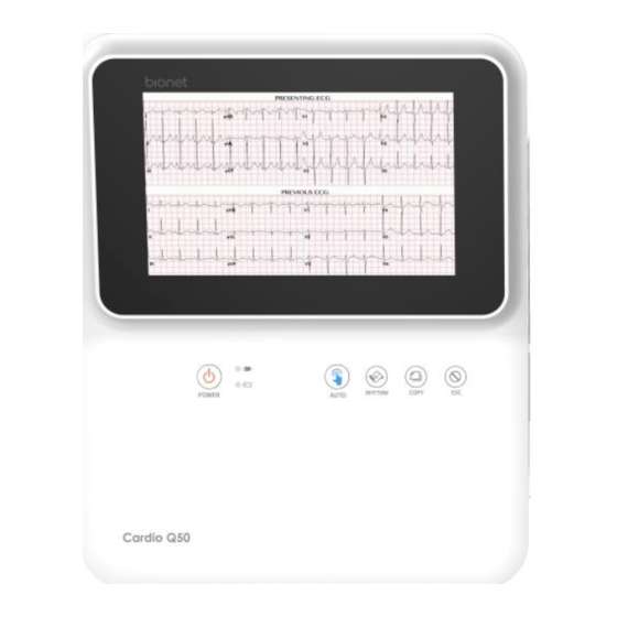
Bionet Cardio Q50 Operation Manual
Electrocardiograph & diagnostic spirometer
Hide thumbs
Also See for Cardio Q50:
- Quick manual (8 pages) ,
- Quick manual (2 pages) ,
- Quick manual (10 pages)

Related Manuals for Bionet Cardio Q50


Summary of Contents for Bionet Cardio Q50
- Page 1 Electrocardiograph & Diagnostic Spirometer Cardio Q50 / Cardio Q70 Operation Manual Ver. 1.01 2023. 06. 07 www.ebionet.com Copyright © 2023 By Bionet Co., Ltd. All rights reserved.
- Page 2 V 1.01 REVISION HISTORY Revision No. Date Contents Page 1.00 2023.03.30 First Written 1.01 2023.06.07 New logo change 2023. 06 2 / 184 Document No.: BN_CQ_OPM_303...
- Page 3 Federal law restricts this device to sale by or on the order of a physician NOTE The product does not have shelf life. Its expected use life is 6.5 years. After 6.5 years, though the product still works normally, it is recommended to have it checked by Bionet. 2023. 06 3 / 184...
- Page 4 Tel : +49-30-240-374-52 E-mail : bionetEU@ebionet.com Website: www.bioneteu.com ※ In the event of a malfunction or failure, contact Service Dept. Of Bionet Co., Ltd. along with the model name, serial number, date of purchase and explanation of failure. 2023. 06 4 / 184 Document No.: BN_CQ_OPM_303...
- Page 5 - Mishaps such as dropping the product. - Using the third party replacements or options not specified by our company. - Non-Bionet technicians or agency technicians in the process of repair. 3. Other cases - Breakdowns by natural disasters (fire, salt damage, flood damage, earthquake, etc.) - When a consumable part has reached the end of its life (accessories) 2023.
- Page 6 V 1.01 Warnings, Cautions, and Notes The following terms are used throughout this manual to emphasize important and critical ⚫ information. You must read these statements to help ensure safety and to prevent product damage. ⚫ The manufacturer or the product distributor is not liable for any loss or damage to the product caused by incorrect use or negligence in product maintenance.
- Page 7 DO NOT connect power DO NOT disjoint or until the product is disassemble the equipment. completely installed. (Bionet is not liable for broken products caused by It may cause damage to attempted disassembly.) the product. 2023. 06 7 / 184...
- Page 8 Mains power should be typical commercial or hospital environment. NOTE Diagnosis provided by Cardio Q50 / Cardio Q70 must be confirmed by a qualified medical professional. NOTE The EMISSIONS characteristics of this equipment make it suitable for use in industrial areas and hospitals (CISPR 11 class A).
- Page 9 V 1.01 CAUTION Warning: MR-unsafe! DO NOT expose the device to a magnetic resonance (MR) environment. The device may present a risk of projectile injury due to the presence • of ferromagnetic materials that can be attracted by the MR magnet core.
- Page 10 V 1.01 Safety Messages The following messages are applied throughout the product. Certain statements may also appear elsewhere in the manual. WARNING: ACCIDENTAL SPILLS — If the equipment is penetrated with liquid, take it out of service and have it checked by a service technician before using it again. DO NOT allow liquids to enter the equipment to prevent electric shock or equipment malfunction.
- Page 11 V 1.01 Therefore, make sure that all external devices operated in the vicinity of the equipment comply with the relevant EMC requirements. X-ray equipment or MRI devices are possible sources of interference as they may emit higher levels of electromagnetic radiation. WARNING: Use of this equipment adjacent to or stacked with other devices should be avoided because it could result in improper operation.
- Page 12 V 1.01 WARNING: SITE REQUIREMENTS - Improper placement of equipment and/or accessories may result in a hazard to the patient, operator, or bystanders. DO NOT route cables in a way that they may present a stumbling hazard. To ensure safety, all connectors on patient cables and lead-wires are designed to prevent inadvertent disconnection, should someone pull on them.
- Page 13 If you have questions concerning the disposal of the product, please contact Bionet or its distributor. CAUTION: EQUIPMENT DAMAGE — Equipment intended for emergency application must not be exposed to low temperatures during storage and transport to avoid moisture condensation at the application site.
- Page 14 V 1.01 In the USA, if the installation of this equipment will use 240V instead of 120V, the source must be center tapped, 240V single-phase circuit. This equipment is suitable for connection to public mains as defined in CISPR 11. Equipment connected to the ECG system and to the patient’s environment must be powered from a medically isolated power source or must be a medically isolated equipment.
- Page 15 V 1.01 Safety Symbols Symbols Description Attention: Consult accompanying documents. Consult Instructions for Use: This symbol advises the reader to consult the operating instructions for information needed for the proper use of the equipment. Safety Sign: It indicates that you should read the user manual. Read the user manual before starting work or operating the equipment.
- Page 16 V 1.01 Symbols Contents Spirometry Connector Local Area Network (LAN) connector Power On / Off Battery Operation Indicator AC Power Connection Indicator Manufactory Authorized Distributor in the European Community Europe Waste of electrical and electronic equipment must not be disposed as unsorted municipal waste and must be collected separately.
- Page 17 V 1.01 Single Use Only Recycling; Dispose of DO NOT reuse the properly in accordance with mouthpiece: it is a all state, provincial and single time use only. national regulations. This way up; For the duration of shipping/delivery, the Fragile; Handle with care. carton should face upright.
-
Page 18: Table Of Contents
V 1.01 Table of Contents Chapter 1. General Rules ................21 1) Product Overview .......................... 21 1-1) Intended Use ..........................21 1-2) Indications ............................ 22 1-3) Contraindications ........................22 1-4) Side Effects ..........................23 1-5) Warnings, Cautions and Adverse Reactions ..............23 2) Recording ECGs during Defibrillation .................. - Page 19 V 1.01 1) Getting Started ..........................120 2) Entering Patient Information ....................120 3) Forced Vital Capacity (FVC) Test ..................123 4) Simple Forced Bital Capacity (SFVC) Test ............... 130 5) Slow Vital Capacity (SVC) Test ..................... 133 6) Maximum Voluntary Ventilation (MVV) Test ..............136 7) Calibration .............................
- Page 20 V 1.01 Specifications or functions described in this user manual are subject to change without notice for product improvement. 2023. 06 20 / 184 Document No.: BN_CQ_OPM_303...
-
Page 21: Chapter 1. General Rules
1-1) Intended Use(Indications for use) The Cardio Q50 / Cardio Q70 ECG Analysis System is intended to acquire, analyze, display and record ECG information from adult and pediatric populations. -
Page 22: 1-2) Indications
V 1.01 The Cardio Q50 / Cardio Q70 is intended to be used by personnel trained in hospitals or medical professional facilities under the direct supervision of a licensed healthcare practitioner. In addition, the Cardio Q50 / Cardio Q70 is intended for prescription use only to perform spirometry diagnostic tests in adults and pediatric patients aged 5 and older in general practice, specialist and hospital settings. -
Page 23: 1-4) Side Effects
Q50 / Cardio Q70 cannot be held responsible and the equipment will no longer be supported. b. The Cardio Q50 / Cardio Q70 is not designed as sterile equipment. Always follow the safety instructions given by the manufacturer of cleaning and disinfectant chemicals. -
Page 24: Recording Ecgs During Defibrillation
A ‘spitting’ action or cough will give false readings. Do not expose the Cardio Q50 / Cardio Q70 to liquids. g. Do not use Cardio Q50 / Cardio Q70 in the presence of flammable liquids or gases, dust, sand or other chemicals. -
Page 25: Product Characteristics
V 1.01 defibrillation-proof, therefore, it is not necessary to remove the ECG electrodes prior to defibrillation. When using stainless steel or silver electrodes a defibrillator discharge current may cause the electrodes to retain a residual charge causing a polarization or DC offset voltage. This electrode polarization will block the acquisition of the ECG signal. - Page 26 V 1.01 - Various protocols are supported to enable connection with the hospital computer network (EMR, PACS, etc.), and File and Worklist DB functions have been enhanced. - You can monitor the lung function progress or the result value in real-time basis on the LCD, and the best result is automatically chosen after 3 or 8 tests.
-
Page 27: Product Configuration
V 1.01 4) Product Configuration The Cardio Q50 / Cardio Q70 system consists of the following components. Open the packaging box and check that all components below are included and make sure that the main body or components are not damaged. - Page 28 V 1.01 ② Patient Cable (1ea.) Photo Description Length: 3,350 mm Weight: 0.386 kg Color: Brown Type: Option Code Number: 152600-019011 (EU) 152600-012811 (US) Length: 3,550 mm Weight: 0.425 kg Color: White Type: Standard Code Number: 152600-044400 (EU) 152600-044500 (US) Length: 3,800 mm Weight: 0.437 kg Color: White...
- Page 29 V 1.01 ▣ Spirometer (accessory) ③ ④ ⑤ ① ⑥ ⑦ ② ① Spiro Handle (1ea.) - Length: 880mm (Normal), 3,480 mm (Max) ② Handle supporter (1ea.) ③ Disposable Mouthpiece (2ea.) ④ Nose Clip (1ea.) ⑤ Mouthpiece Adapter (1ea.) ⑥ Diagnostic Guide (1ea.) ⑦...
- Page 30 Be sure to use genuine accessories supplied by Bionet. WARNING Bionet is not liable for any problems caused by you not using the battery provided by Bionet. Make sure to use the genuine battery provided by Bionet.
- Page 31 V 1.01 Body Configuration ▣ Top View ① ② ④ ③ ⑤ ① LCD: It displays the operation status. ② LED: It shows the power connection status and battery status. ③ Power Switch: Power On/Off (Press longer than 3 seconds.) ④...
- Page 32 V 1.01 ▣ Bottom View ① ① Battery Cover: Insert a rechargeable battery here. ▣ Front View 2023. 06 32 / 184 Document No.: BN_CQ_OPM_303...
- Page 33 V 1.01 ▣ Rear View ① ② ③ ④ ⑤ ① AC Power Terminal: AC power connection ② Grounding Terminal: Connect it to an external ground terminal if there is no protective grounding in the power supply. ③ USB Port: USB connection with external devices ④...
- Page 34 NOTE Do not open the cover of the equipment; it may cause an electric shock. Repair or disassembly of the equipment can only be performed by those who have product repair qualifications recognized by Bionet. 2023. 06 34 / 184...
- Page 35 V 1.01 2023. 06 35 / 184 Document No.: BN_CQ_OPM_303...
- Page 36 V 1.01 Spirometer Handle Configuration ▣ Front View of Spiro Handle 1. Front Cover: Mouthpiece anchoring cover 2. Front Cover Lock Switch: It locks the mouthpiece anchoring cover. 3. Operation Lamp: It shows the operation status (green). 4. Mouthpiece Hole: The mouthpiece is inserted into this hole. 2023.
- Page 37 V 1.01 ▣ Left Side of Spiro Handle 1. Front Cover: Mouthpiece anchoring cover 2. Front Cover Lock Switch: It locks the mouthpiece anchoring cover. 3. Connected Wires: They are connected to the back of the main body. 4. Mouthpiece Hole: The mouthpiece is inserted into this hole. 2023.
- Page 38 V 1.01 ▣ Right Side of Spiro Handle 1. Front Cover: Mouthpiece anchoring cover 2. Connected Wires: They are connected to the back of the main body. 3. Mouthpiece Hole: Insert the mouthpiece into this hole. 2023. 06 38 / 184 Document No.: BN_CQ_OPM_303...
- Page 39 V 1.01 ▣ Rear View of Spiro Handle 1. Front Cover: Mouthpiece anchoring cover 2. Front Cover Lock Switch: It locks the mouthpiece anchoring cover. 3. Connected Wires: They are connected to the back of the main body. 4. Mouthpiece Hole: The mouthpiece is inserted into this hole. 2023.
- Page 40 V 1.01 Front Part Graphic Display Window Power Key Function Keys 2023. 06 40 / 184 Document No.: BN_CQ_OPM_303...
- Page 41 V 1.01 ECG Graphic Window Refer to the following description about the ECG graphic window. ① ② ③ ④ ⑤ ⑥ ⑦ ⑧ ⑨ ⑩ ⑪ ⑫ ⑬ ⑭ ⑮ ⑯ ⑰ ① Patient ID and name: Touch this button to enter patient information. ②...
- Page 42 V 1.01 ⑫ Current gain: Touch this button to set Gain. ⑬ Filter: Touch this button to set a filter. ⑭ Print Form: Touch this button to set screen output and print form. ⑮ Disclosure: Touch this button to run Disclosure. Setup Menu ⑯...
- Page 43 V 1.01 ⑤ Spiro Handle connection icon ⑥ Network connection status: Touch this button to set the network. ⑦ Battery status or AC power connection status ⑧ Current date and time: Touch this button to set the date and time. ⑨...
- Page 44 V 1.01 RHYTHM ② A real-time ECG waveform is continuously printed or prepared as a report. COPY ③ Previously saved data will be processed and printed in the same way as before or as modified in your settings. ④ You can cancel the operation or switch to the previous mode by entering the main menu.
- Page 45 NOTE Bionet recommends replacing the lithium-ion battery after 24 months of use. Battery life depends on the frequency of use. Continued use by the battery power reduces the battery life and shortens the time of replacement.
- Page 46 Do not use a damaged battery on the equipment. WARNING Pay attention to the polarity when replacing the battery. Bionet strongly recommends using the battery provided with the equipment. Using an unauthorized battery may damage the equipment. The Effect of Lithium-Ion Technology on the Battery Find out about lithium-ion battery technology here.
- Page 47 V 1.01 caused by the current demanded by the lithium-ion battery integrated circuit. Battery is self- discharged due to the nature of lithium-ion cells, and the self-discharge rate doubles for every 10°C (18°F) rise in temperature. Battery retention loss is greater at higher temperatures. As the battery ages, it may not be fully charged, as a result, the total charge capacity used for saving and using gradually decreases.
-
Page 48: Installing System
5) Installing System Installation Precautions Note the following when installing the Cardio Q50 / Cardio Q70. - Use the equipment within the ambient temperature of 10~40℃ and humidity of 30~85%. - Check the connection of the power cord and handle the patient cable with care. - Page 49 V 1.01 Inserting ECG Recording Paper Pull forward the printer handle on the frontㅇ of the equipment to take out the printer tray. Insert the ECG recording paper with the area to be printed facing up as shown in the picture, making sure that the black mark on the paper is located at the bottom.
- Page 50 V 1.01 ⚫ Tear the printed paper from the top or bottom along the dotted line. ⚫ Do not pull the ECG recording paper while being printed. Take the following measures for paper jams: ⚫ 1) Turn off the equipment. 2) Pull the printer tray forward to take it out.
- Page 51 V 1.01 WARNING Use only the ECG recording paper provided by Bionet for ECG recording. Otherwise, the poor printing quality may affect the doctor's diagnosis. Bionet is not liable for any problems caused by you not using the ECG recording paper provided by Bionet.
- Page 52 • If the equipment is used as a layer-2-switch or layer-3-switch, the port settings must be configured on the network switch. Configure the network of Bionet equipment to be compatible with the specifications of your operating organization. The equipment exchanges data with other medical devices via a LAN network. The network must...
- Page 53 ⚫ Security of the network is the sole responsibility of the network operator. ⚫ Bionet recommends the following to guarantee the security of the network. ⚫ Define access authorization for the configuration of the host system so that no unauthorized alterations of the system can occur.
-
Page 54: Starting The System
V 1.01 6) Starting the System When you turn on the equipment, the product name is displayed and the login screen appears as shown in the picture below. Enter your user information to log in. Login Enter your ID and password. Roles and privileges are assigned to individual users and may affect each user's scope of access to areas of the workflow and available functions. - Page 55 V 1.01 Touch a menu to load the corresponding main screen. The picture below shows the ECG main screen that is loaded when you choose the ECG menu. The following is a description of the ECG initial screen menu. Menu Description Patient information ECG Recording mode...
- Page 56 V 1.01 Lead Fault information Move to Retry Queue (to manage files that failed to be sent to server). Barcode reader connection status USB Memory connection status Current network connection status: Touch this icon to set. Power status (AC power or battery) Current date and time: Touch this icon to set date and time.
- Page 57 V 1.01 Touch [Worklist] to bring up the exam-requested patient management screen as follows. The following is a description of the Worklist menu. Menu Description Search data by entering search criteria. Order number in the current location/entire order number Go to the previous page. Go to the next page.
- Page 58 V 1.01 Touch [File] to bring up the ECG data management screen as follows. The following is a description of the File menu. Menu Description Search data by entering search criteria. File number on the current location/entire file number Go to the previous page. Go to the next page.
- Page 59 V 1.01 Touch (Retry Queue icon) to bring up the Retry Queue data management screen as follows. Retry Queue manages data that has failed to be sent to the server. The following is a description of the Retry Queue management menu. Menu Description File number on the current location/entire file number...
-
Page 60: Part 1 Recording Ecg
V 1.01 Part 1 Recording ECG 2023. 06 60 / 184 Document No.: BN_CQ_OPM_303... -
Page 61: Chapter 2. Ecg Recording Preparation
V 1.01 Chapter 2. ECG Recording Preparation 1) Attaching the Electrodes When you touch (Lead Fault Information) located in the center of the menu bar at the top of the ECG Main screen, a picture showing where to attach the electrodes is displayed. -
Page 62: Connecting Electrodes
Connect the patient cable to the port on the right side of body and connect limb electrodes to the terminals of RL (N), LL (F), RA (R), and LA (L) of patient cable connected in the Cardio Q50 / Cardio Q70 and chest electrodes to the terminals V1 (C1), V2 (C2), V3 (C3), V4 (C4), V5 (C5) and V6 (C6). - Page 63 - When conductivity between the skin and the electrodes is weak: Apply the ECG gel to the electrode-attaching spots and reattach the electrodes. If the ECG signal is not accurately acquired even after you try all the solutions above, the patient cable may be non-conforming. Contact Bionet's service center. 2023. 06 63 / 184...
-
Page 64: Recording Ecg
V 1.01 3) Recording ECG - Enter accurate patient information. - Connect the ECG cable to the patient in compliance with the ECG measurement preparations. - Check or change settings such as Filter, Gain, Output Speed, Channel Configuration, Rhythm, etc. - Refer to What to Do with Poor Lead Connection if the waveform drawn in the LCD screen is abnormal or there is too much noise. -
Page 65: Basic Setup
V 1.01 4) Basic Setup General Information When you turn on the equipment, top and bottom menu bars and graphic window appear on the LCD screen. Top menu bar: Patient Information, Test Mode, Heart Rate, Lead Fault, External Device Connection Status, Network Status, Power Status, Current Date and Time Bottom menu bar: Output Speed, Gain, Filter, Print Form, Disclosure, and Setup. - Page 66 V 1.01 In 3x4+1 mode, the waveform is drawn as below. The background color of the screen output of the ECG waveform can be white or black, which you can change in the Setup → ECG → General → Background menu. In the black background, the waveform is drawn without a grid as shown below.
- Page 67 V 1.01 Patient Information Enter the patient's ID, name, age, gender, height, and weight. Fields marked with are required inputs. Automatic diagnosis is made based on the ECG recording for 10 seconds and is available for pediatrics and adults. It is carried out according to the age of the patient. Patient ID Enter a unique number used in the hospital to classify patient medical data.
- Page 68 V 1.01 You cannot use \ ’ , . / * | : ” < > ? characters for ID. Use only plain alphabets and numbers for ID. If you enter an ID in Latin extended characters or Russian, an error may occur when you transfer files with the IDs to a PC or USB memory.
- Page 69 V 1.01 Enter the patient's age directly. Enter the age of pediatrics or adults. Enter the age in weeks or days if you cannot enter the age in years. NOTE - Age is automatically calculated when the date of birth is entered. - If age is not entered, an adult diagnosis is provided.
- Page 70 However, since the default setting of the entry method of each product may be different, check the method supported by Bionet before using them. Entry methods supported by Bionet products: International standard and USB ⚫ The products that have been tested by connecting to Bionet equipment are listed ⚫ below. 2023. 06 70 / 184 Document No.: BN_CQ_OPM_303...
- Page 71 V 1.01 Manufacturer Product Name Product Image Symbol LS-2208 ZEBEX Z-3110 Honeywell MS5145 Honeywell DS2208 NOTE Each barcode reader has a product-specific initialization code. Be sure to read the user manual of the product and check the entry method before initializing Output Speed Adjust the width of the output signal for screen output and printout.
- Page 72 V 1.01 NOTE - If you set the Rhythm Size of monitoring to Report, the signal is always printed at 25mm/sec regardless of the Output Speed setting. - When you set the recording mode to 1min, the signal is always printed at 25mm/sec.
- Page 73 V 1.01 NOTE When you set the recording mode to 3, 5, 10, 20 and 30min, the printing size is fixed at 5.0mm/mV. Filter The ECG signal may contain not only ECG data, but also power noise, baseline drift by breathing, and EMG signals.
- Page 74 Print form. NOTE Bionet recommends always using a Baseline Drift filter of 0.1Hz, an AC filter of 50Hz or 60Hz, and an LPF filter of 150Hz. If noise is severe, use an EMG filter appropriately. You can get the best signal by using the recommended filter;...
- Page 75 V 1.01 10-second resting ECG recording: I, II, and III in the first 2.5 seconds; aVR, aVL, and aVF in the next 2.5 second; V1, V2, and 3CH+1 V3 in the next 2.5 seconds; and V4, V5, and V6 in the next 2.5 seconds.
- Page 76 V 1.01 The representative beat and each diagnostic parameters are printed, ST Map (B) drawing ST map in the form of Bar. The representative beat and each diagnostic parameters are printed, ST Map (D) drawing ST map in the form of Dot. Presentation Format Set the presentation format of 12-lead ECG.
- Page 77 V 1.01 Rhythm Report (Rhythm Size) Sets the report size of the real-time print. - Report: About 10 seconds of data are printed in Report format. - Continue: The pre-set lead is continuously printed until you press the [ESC] key on the control panel.
- Page 78 V 1.01 Rhythm Print Format (6CH) Rhythm Print Format (12CH) 2023. 06 78 / 184 Document No.: BN_CQ_OPM_303...
- Page 79 V 1.01 Diagnosis Print Format (3CH + 3RHY) Diagnosis Print Format (3CH + 1RHY) 2023. 06 79 / 184 Document No.: BN_CQ_OPM_303...
- Page 80 V 1.01 Diagnosis Print Format (6CH + 1RHY) Diagnosis Print Format (12CH) 2023. 06 80 / 184 Document No.: BN_CQ_OPM_303...
- Page 81 V 1.01 Diagnosis Print Format (6CH+1 (ST)) Record Report Form (1CH +3) 2023. 06 81 / 184 Document No.: BN_CQ_OPM_303...
- Page 82 V 1.01 Record Report Form (Cabrera Report) Diagnosis Print Format (BEAT REPORT-TEXT) 2023. 06 82 / 184 Document No.: BN_CQ_OPM_303...
- Page 83 V 1.01 Diagnosis Print Format (BEAT REPORT-VECTOR) Diagnosis Print Format (BEAT REPORT-GUIDE) 2023. 06 83 / 184 Document No.: BN_CQ_OPM_303...
- Page 84 V 1.01 Diagnosis Print Format (BEAT REPORT-ST Map (B)) Diagnosis Print Format (BEAT REPORT-ST Map (D)) 2023. 06 84 / 184 Document No.: BN_CQ_OPM_303...
- Page 85 V 1.01 * Explanation of BEAT REPORT Variables PR: PR Interval PA: Amplitude of P Wave (P Amplitude) PD: Duration of P Wave (P Duration) QA: Amplitude of Q Wave (Q Amplitude) QD: Duration of Q Wave (Q Duration) RA: Amplitude of R Wave (R Amplitude) RD: Duration of R Wave (R Duration) SA: Amplitude of S Wave (S Amplitude) SD: Duration of S Wave (S Duration)
- Page 86 V 1.01 NOTE Dextrocardia Normally, the heart is located in the left chest. However, there are cases where the heart is located in the right chest, which is called Dextrocardia. You may suspect Dextrocardia in the following cases: - If P, QRS and T are all reversed in Lead I - If aVR and aVL are switched, and lead II and III are switched - If R wave becomes smaller from V1 to V6 in chest lead For Dextrocardia patients, change the electrode positions and measure as follows to obtain...
-
Page 87: Disclosure
V 1.01 5) Disclosure Touch the button on the menu bar at the bottom of the ECG main screen to switch to Disclosure screen. Disclosure is a function that stores ECG data in the equipment memory and shows it when executed. In the Disclosure screen: The pre-stored 30 minutes of ECG data are displayed in 1CH. - Page 88 V 1.01 ② ECG recording mode (10s, 1m, 3m, 5m, 10m, 20m, or 30m): Touch this button to set a mode. ③ Number of events (Arrhythmia): Touch this button to set Event List (Arrhythmia History). ④ Lead: Touch this button to select a lead. ⑤...
- Page 89 V 1.01 The abbreviation of the diagnosis name displayed on the screen is as follows: Abbreviations Diagnosis Bigeminy PVC Bigeminy Trigeminy PVC Trigeminy Couplet PVC Couplet ShortRun Short run of PVC Vtachy Ventricular Tachycardia Vrhythm Ventricular Rhythm Vbrady Ventricular Bradycardia Paced Pacemaker Rhythm Asystole...
-
Page 90: Real-Time Printing (Rhythm Key)
Occurs when a ventricular complex is detected within the repolarization period of a Non-ventricular beat. NOTE The diagnosis provided by Cardio Q50 / Cardio Q70 must be confirmed by a qualified medical professional. 6) Real-time Printing (RHYTHM Key) Press the [RHYTHM] key on the control panel to print the ECG signal in real-time. -
Page 91: One-Key Diagnosis (Auto Key)
V 1.01 NOTE Do not attempt to attach or detach a USB device while the printer is working as it may cause the printer module to rattle. 7) One-key Diagnosis (AUTO key) Press the [AUTO] key shortly to diagnose the ECG acquired during the set duration, and to save, transmit, and print the result. -
Page 92: Printing Diagnostic Copy (Copy Key)
V 1.01 Touch [OK] if the data is reliable. NOTE Set Preview settings in Setup→ ECG → Record → Preview. Recording Long-term ECG Touch the ECG recording mode at the top of the ECG main screen and set the duration to 1, 3, 5, 10, 20 or 30 minutes. -
Page 93: System Settings
V 1.01 NOTE You cannot use COPY key function if you change the diagnosis mode after a diagnosis is issued. 9) System Settings Set up various items related to the equipment in the Setup menu. The top menu bar has a network icon and date/time button, and the bottom menu bar has a Setup button to configure the equipment settings. - Page 94 V 1.01 NOTE - If any of Year, Month, Day, Hour, or Minute are changed in the Date and Time Settings, the Second value is automatically initialized to 00, which cannot be set arbitrarily. - If the system date and time are changed, all Disclosure Data recorded in the equipment will be deleted.
- Page 95 IP registered in the PACS server, server connection may not be made. Setting Wireless Network Plug a USB wireless LAN card into the USB port of Cardio Q50 / Cardio Q70 to set up the wireless network. Wireless Select Wired or Wireless for network connection.
- Page 96 Use an internationally certified Wi-Fi dongle. Bionet does not manufacture or provide Wi-Fi dongles. You can use any Wi-Fi dongle using one of the 9 chipsets listed above. The Wi-Fi dongle that Bionet tested as a representative model is T2U AC600, which is widely used and internationally certified.
- Page 97 Automatically connected APs without security keys do not guarantee communication security. NOTE Bionet recommends using English alphabet to name the wireless network (SSID) of the AP. Inputs in Korean or other languages can be shown broken or as strange characters.
- Page 98 V 1.01 Setting ECG-General Filter Refer to the Filter section described earlier in the manual. Gain Refer to the Gain section described earlier in the manual. Speed Refer to the Output Speed section described earlier in the manual. Display Form Set the display form of the ECG waveform drawn on the ECG main screen.
- Page 99 V 1.01 To cancel the Demo, turn off and on the equipment. Setting the Lead Fault A lead fault may occur if the lead connection of the patient cable is unstable. Set whether or not to display the Lead Fault message in this case. Set it to On to show a Lead Fault message or Off not to.
- Page 100 V 1.01 Setting ECG Recording Analysis Level Set the Automatic Diagnosis level of the 10-second recording. Basic level: Provides only serious diagnoses with the diagnostic criteria value is raised. Professional level: Various diagnoses are provided according to the standard diagnosis criteria. ST Analysis Set the ST Segment diagnosis during automatic diagnosis on 10-second recording.
- Page 101 V 1.01 Long-Term ECG Setting Leads Use Long-term ECG recording to output 1CH for a longer term such as 1, 3, 5, or 10 minutes, Set the lead to provide the long-term output. NOTE Set Lead II because it is the largest in general, however, if its waveform is not large enough, choose another lead with the largest and best waveform.
- Page 102 - Quick Print option is available only for 10-second recording. It cannot be used for long- term (1 minute, 3 minutes, 5 minutes, 10 minutes, 20 minutes, or 30 minutes) recordings. - If you want to be provided with the arrhythmia section, Bionet recommends using the Disclosure function.
- Page 103 QTc estimates the QT interval at a standard heart rate of 60 bpm. 4 official formulas: Bazett, Hodges, Fridericia, and Framingham Algorithm Choose an algorithm (Bionet or Glasgow) to analyze the 10-second data. Electrodes When using the Glasgow algorithm, choose between standard 12-lead and pediatric V4R.
- Page 104 V 1.01 diagnosis on the ECG main screen. Setting the System Configure system settings. Set each group: General, Hospital, Server, Printer, and Service Setting System-General Language Select the language and touch [OK]. NOTE Even if the set language is not English, some terms, such as diagnosis names, may be shown in English.
- Page 105 V 1.01 Start Option Set the initial screen that appears when the equipment is turned on. Select the most frequently used function among Main, ECG, Spiro, File, and Worklist. Date Format Set the date format. The set format is applied both on the screen output and printout. Height Unit inches Set the unit to enter the patient's height.
- Page 106 V 1.01 Setting a Hospital Hospital Information Enter the name of the hospital. Doctor Information Enter the name of the doctor. Setting a Server Connecting to a Server (Connect to) Select a server to which the equipment connects among EMR, PACS, GET and WEB servers. Select a server you want to connect to and touch [Edit].
- Page 107 V 1.01 Setting EMR Server (EMR Server Edit) Protocol Select a protocol to share the files among FTP, SMB v1, and SMB v2. Server IP Enter the IP of the file-sharing server. Shared Folder Address Enter the path of the file-sharing folder. Enter the ID to use to share files.
- Page 108 V 1.01 Setting PACS Equipment Information (Device) AE Title and Port Enter AE Title and Port for the Cardio Q50 / Cardio Q70. Modality Enter the Modality of ECG and Spiro. Spiro Exam Code Enter the Exam Code for FVC, SFVC, SVC, and MVV exams of Spiro.
- Page 109 V 1.01 Date Range Set the date range to import a worklist from the Worklist server. Type Description Today's worklist is loaded. Today (today-today) Set both start and end dates to today. Today's worklist is loaded Today (today-blank) Set only start date to today. Yesterday-Tomorrow A worklist from yesterday to tomorrow is loaded One Week...
- Page 110 Work Type Set the GDT operation of the equipment. - Server: Cardio Q50 / Cardio Q70 receives requests and commands. - Client: Cardio Q50 / Cardio Q70 sends requests and commands. Shared Forder Enter the format of sharing folder information and date to be used by the GDT protocol.
- Page 111 Each name of EMR and Cardio Q50 / Cardio Q70 Short Name Date format of the file. It is a 3-letter abbreviation for each of the EMR and Cardio Q50 / Cardio Q70 to be used for the GDT protocol. File Name Select the name type of the file to be shared by the GDT protocol.
- Page 112 V 1.01 Setting Web (WEB Setting) When you select Web transmission, set additional information in Setting menu. A screen appears to set URL, Path, ID, PW, and DNS. The web address to connect to Path The path within the server to transmit the files to The user ID to use on the web to access Password The user password to use on the web to access...
- Page 113 V 1.01 Setting System Printer Paper Size Set the size of the paper. - A4: A4 size paper - Letter: The letter size paper Print Line Set the boldness of printout. There are three options: thin, normal and thick. Test Print As a print quality test, two test patterns including grid and triangular waveform are printed.
- Page 114 You are moved to the User Information Management for Equipment Use. See Chapter 7 User Information Management. NOTE Contact the Bionet service center when you forget your password. NOTE Rules for Creating Passwords - 10 or more characters: a combination of two of uppercase letters, lowercase letters, numbers, and special characters.
- Page 115 V 1.01 System Information Device ID Enter a unique ID for the equipment. Device Alias Enter an alias for the equipment. More Information (More Information) Touch for more information for the equipment. Setting Security Auto Standby Set On/Off to activate the standby mode for a security purpose when the equipment is not used for the timeout period.
- Page 116 V 1.01 Single Sign On Because single sign-on can compromise security, Bionet recommends this setting only for the devices used single or a limited user. Activate it to enable system authentication of user ID and password. If it is set, no login is required at the start of the program because user authentication is carried out by the equipment.
-
Page 117: Part 2 Using Spirometer
V 1.01 Part 2 Using Spirometer 2023. 06 117 / 184 Document No.: BN_CQ_OPM_303... -
Page 118: Chapter 3. How To Install
V 1.01 Chapter 3. How to Install 1) Connecting Spirometer Handle Connect the connection terminal of the spiro handle to the USB port on the back of the main unit. <Side> (1) Connect the spiro handle with the equipment powered off. (2) Turn on the power switch of the equipment. - Page 119 V 1.01 (1) Press the Front Cover Lock Switch on the top left corner of spirometer handle and open the Front Cover in semi-circle shape. (2) Put the mouthpiece on the inserting lot made on the open side. (3) Press the Front Cover with a little force to close it.
-
Page 120: Chapter 4. How To Use
V 1.01 Chapter 4. How to Use 1) Getting Started Turn on the equipment and touch [Spiro] to enter the spirometer main screen. <Spirometer main screen> Touch one of the items on the screen above. Touch the buttons on the screen to make them function. 2) Entering Patient Information Enter the patient's personal information before starting the lung function test. - Page 121 V 1.01 Patient ID Enter a unique number used in the hospital to classify patient medical data. Touch the input field of ID to display the keypad window consisting of alphabets and numbers. Use the keypad window to enter patient ID. Touch the (Caps Lock) key at the bottom left to switch from lowercase to uppercase or vice versa.
- Page 122 V 1.01 Date of Birth (Birthday) Touch the input field of Birthday to display a number pad as below. Enter the patient's date of birth. Patient's age is automatically calculated and entered. Enter the patient's age directly. Gender Touch the input field of Gender to select Male or Female. Height Enter the patient height in the same way as entering the age.
-
Page 123: Forced Vital Capacity (Fvc) Test
V 1.01 Urgent Mark whether the patient needs urgent care. Other Information Enter Department, Room No., Study Description, Accession No., and Referring Physician in the same way as entering ID. Touch [OK] to save the settings or [Cancel] to cancel the settings. Touch [New] to initialize all the patient information you have entered. - Page 124 V 1.01 The following screen appears if the spiro handle is connected well. Now you are ready to start the FVC test. Have the patient hold the spiro handle and place it in front of his or her mouth, and touch [Start]. When the equipment sounds a beep indicating the start of the test, have the patient bite the mouthpiece and start the test.
- Page 125 V 1.01 3) Exhale as fast and much as possible. (Forced expiration) Exhale as fast as possible and also as much as possible. Try to blow off all 6 candles in the candlelight animation. 1 candle means 1 second. 4) Inhale fast and much as possible. (Forced inspiration) Now that you are running out of breath, you are naturally panting for breath, but you should try your best to inhale as much as possible, not to inhale in order to overcome your...
- Page 126 V 1.01 Result Screen Touch [Stop] after the test to open the result screen. ③ ④ ① ② ① Flow Volume Graph ② Volume Time Graph ③ Parameters ④ Best Result Selecting Best Result After the test, the BEST result number is indicated, which is chosen by the measurement data. The best result is the maximum value of FVC+FEV1.
- Page 127 V 1.01 Print Print out the test result. NOTE Do not attempt to attach or detach a USB device while the printer is working as it may cause the printer module to rattle. 2023. 06 127 / 184 Document No.: BN_CQ_OPM_303...
- Page 128 V 1.01 Network Send the test result to the server. Auto Auto function saves, transmits, and prints test results at once. It functions according to the AUTO key settings set in System General Setup. Exit End the test and return to the Spiro main screen. Set save option in Setup →...
- Page 129 V 1.01 (5) Test in the same way as the FVC base test. (6) Print the test results and compare parameters and graphs of Base test (before taking drugs) and Post test (after taking drugs). (7) Touch [Exit] to end the test. In the File list, you can see the data where the study type of the patient ID is marked as FVC+.
-
Page 130: Simple Forced Bital Capacity (Sfvc) Test
V 1.01 - FVC Post Test Printout 4) Simple Forced Vital Capacity (SFVC) Test SFVC is an abbreviation of Simple Forced Vital Capacity. To test SFVC, touch [SFVC] on the Spirometer initial screen. When you select SFVC, the SFVC test screen appears. Have the patient hold the spiro handle and place it in front of his or her mouth, and touch [Start]. - Page 131 V 1.01 < How to Breathe during SFVC Test > 1) Inhale as much as possible. Inhale as much as possible regardless of the speed. (Instruct the patient to inhale as much as he or she can.) 2) Exhale slowly as much as possible. Exhale as much as possible for more than 6 seconds until you have no more breath left.
- Page 132 V 1.01 Results Screen Touch [Stop] after the test to open the result screen. The best result is the maximum value of FEV1+FEV6. Use the Best, New, Print, Network, Auto, and Exit menus in the same way as in the FVC test. - SFVC Post Test Printout 2023.
-
Page 133: Slow Vital Capacity (Svc) Test
V 1.01 5) Slow Vital Capacity (SVC) Test Touch [SVC] in the Spiro main screen to start SVC testing. Have the patient hold the spiro handle and place it in front of his or her mouth, and touch [Start]. When the equipment sounds a beep, have the patient bite the mouthpiece and start the test. Follow the procedure below to achieve accurate test result. - Page 134 V 1.01 3) Inhale slowly as much as possible (TLC level). 4) Return to normal breathing. If you breathe in the above order, the breathing speed is shown on the graph (V-T). Breathing as usual is shown smaller and a bigger graph is shown on the screen if you have followed the order from 2) to 3).
- Page 135 V 1.01 The best result is the maximum value of SVC. Use the Best, New, Print, Network, Auto, and Exit menus in the same way as in the FVC test. - SVC Test Printout 2023. 06 135 / 184 Document No.: BN_CQ_OPM_303...
-
Page 136: Maximum Voluntary Ventilation (Mvv) Test
V 1.01 6) Maximum Voluntary Ventilation (MVV) Test Touch [MVV] in the Spiro main screen to start MVV testing. Touch [Start] in the screen shown below to start a test. Have the patient hold the spiro handle and place it in front of his or her mouth, and touch [Start]. When the equipment sounds a beep, have the patient bite the mouthpiece and start the test. - Page 137 V 1.01 When the set time (TMVV) - 12 seconds - passes, the test ends and the result is displayed on the screen. MVV, respiratory cycle (FB), and total respiratory capacity (TV) are calculated and displayed at the top of the screen. Touch [Stop] to finish during the test. You are moved to the initial MVV test screen.
-
Page 138: Calibration
V 1.01 7) Calibration Touch [CAL] in the Spiro main screen to start Calibration. On the screen below, touch [Start] to start Calibration. Proceed with the calibration in the following order. Follow the procedure below to achieve accurate test result. 1) Connect the spiro handle to the equipment. - Page 139 Touch [Exit] to finish Calibration and return to the top menu. NOTE - Bionet recommends quarterly calibration of spirometer measuring device. Be sure to perform calibration when changes in temperature and air pressure are significant. Repeat the calibration until the calibration result falls within ±3%.
- Page 140 V 1.01 - Calibration results printout 2023. 06 140 / 184 Document No.: BN_CQ_OPM_303...
-
Page 141: Setting Spiro
V 1.01 8) Setting Spiro Touch [Setup] on the lower menu bar of the Spiro main screen to change the settings. You can set Spiro-related settings for each group. Touch [Default] to enter default values for each input field in the current screen. Touch [OK] to save the settings or [Cancel] to cancel them. - Page 142 V 1.01 Test Count Set the number of tests. In general, set 3 times, but set 8 times for special health checkups. Post Test The FVC Test is divided into: A Base test before taking drugs and a Post test after taking drugs. To conduct Post test, set it On.
- Page 143 V 1.01 FVC Print Drawing Graphs Set whether to draw all graphs or only the best graph of FVC test. When set to All, all tested graphs are drawn, and when set to Best, only the graph selected as Best is drawn. NOTE Even if the FVC Graph is set to All, only the best graph is drawn after FVC Post test.
- Page 144 V 1.01 Setting Spiro Test Environment Touch each input field of Pressure, Humidity, Temp and Syringe to enter values. 2023. 06 144 / 184 Document No.: BN_CQ_OPM_303...
-
Page 145: Part 3 Data And System Management
V 1.01 Part 3 Data and System Management 2023. 06 145 / 184 Document No.: BN_CQ_OPM_303... -
Page 146: Chapter 5. Exam-Requested Data Management
V 1.01 Chapter 5. Exam-requested Data Management 1) Screen Description ① ② ③ ④ ⑤ ⑥ ⑦ ⑧ ⑨ ⑩ ⑪ ⑫ ⑬ ⑭ ⑮ ① Worklist Search ② Go to the previous page. ③ Current page/total number of file pages ④... -
Page 147: Functions
V 1.01 ⑭ Setup Menu ⑮ Touch this button to move to other menus such as ECG, Spiro, File, or Worklist. 2) Functions Search Touch the magnifying glass button at the top left of the screen to enter a search condition. Touch Search Item to enter ID, Name, Accession No., Age, and Date. -
Page 148: System Settings
V 1.01 to that patient's exam screen. When scanning a barcode, select a search item in Setup → Worklist → General → Barcode Search. Search items are ID, Name, and Accession No. When the patient's information is not found in the list on the screen, if PACS server is connected, patient information is searched in the server and shown in the exam screen. - Page 149 V 1.01 Worklist General Setup Barcode Search Scan the patient's barcode with a barcode reader on the worklist screen to automatically move to that patient's exam screen. Set the search items such as among ID, Name, and Accession Display Table item Set the items to be shown on the worklist main screen.
-
Page 150: Chapter 6. Data Management
V 1.01 Chapter 6. Data Management 1) Screen Description ① ② ③ ④ ⑤ ⑥ ⑦ ⑧ ⑨ ⑩ ⑪ ⑫ ⑬ ⑭ ⑮ ⑯ ⑰ ① File list Search ② Go to the previous page. ③ Current page/total number of file pages ④... -
Page 151: Functions
V 1.01 ⑮ Patient information Setup Menu Button ⑯ Touch this button to move to other menus such as ECG, Spiro, File, or Worklist. ⑰ 2) Functions Searching Files Touch the magnifying glass button at the top left of the screen to enter a search condition. Touch Search Item to enter ID, Name, Accession No., Age, and Date. - Page 152 V 1.01 Printing Files (Print) Print the selected files. You can print one or multiple files. NOTE Do not attempt to attach or detach a USB device while the printer is working as it may cause the printer module to rattle. Deleting Files (Delete) Delete the selected files.
-
Page 153: Setup
Set the items to be shown on the File main screen. Changing display items triggers auto-adjustment of spacing between them. Removing Old Files Set whether to delete files between Manual and Auto when the internal memory of Cardio Q50 / Cardio Q70 is full. - Manual: Delete files yourself. - Page 154 The Bionet format of the Cardio Q50 / Cardio Q70 supports Json format. ⚫ Format to be compatible in other ECG equipment of Bionet shall be designated as old Bionet. The old Bionet format only supports 10-second resting ECG, FVC base test (3 counts) ⚫...
- Page 155 V 1.01 Deleting Files Set whether or not to delete the files on Cardio Q50 / Cardio Q70 after they are transferred to the server. To delete, set it to On. NOTE The Delete option applies only when files are sent to the server. Files sent to USB memory are not deleted.
- Page 156 V 1.01 On PACS system, Window Width and Center are usually set to their Window Width / default values. If the images in the transmitted files are blurry, enter the Window Center Window Width and Center values that the PACS server supports. Security Options (Hide Information) Set to Hide for security purposes to screen the file information when printing or transferring files of all formats.
- Page 157 V 1.01 File Autokey Setup AUTO Key Set AUTO Key function such as storing, printing, and transmitting as below. Saving Results (Store) Set whether to save the test data. To save the test result automatically in the internal memory, set it to On. Otherwise, set it to Off. Check the saved data in the File main screen.
-
Page 158: Transmitting Data (Network)
Bionet recommends backing up data on an existing storage device before connecting ⚫ a new storage device. The file format of USB memory supported by Cardio Q50 / Cardio Q70 is FAT32. ⚫ USB external HDD is not supported. ⚫... -
Page 159: Importing Data
V 1.01 4) Importing Data On the file screen, press the [COPY] key on the control panel to import the data in Bionet format saved in the USB memory to equipment. Press the [COPY] key on the control panel: the following screen appears. -
Page 160: Chapter 7. User Information Management
V 1.01 Chapter 7. User Information Management 1) Screen Description ① ② ③ ④ ⑤ ⑥ ⑦ ⑧ ⑨ ⑩ ⑪ ⑫ ⑬ ⑭ ⑮ ⑯ ① Go to the previous page. ② Current page/total number of file pages ③ Go to the next page. ④... -
Page 161: Functions
V 1.01 2) Functions To select multiple users, touch [Select] and then touch the checkboxes in front of the IDs. To select all users, touch button shown in the title bar of the user list. Selecting a User Touch the user list to select users. Adding a User (User Add) Touch this button to add a user. - Page 162 Bionet recommends backing up data on an existing storage device before connecting a ⚫ new storage device. The file format of USB memory supported by Cardio Q50 / Cardio Q70 is FAT32. ⚫ USB external HDD is not supported. ⚫...
-
Page 163: Chapter 8. System Management
Chapter 8. System Management 1) Maintenance and Cleanliness Keep Cardio Q50 / Cardio Q70 equipment and handles clean. Avoid damaging or contaminating the equipment using the methods recommended below. If you use the substances - including not allowed substances - that can damage on the product, warranty is not applied even during the warranty period. -
Page 164: Regular Examination
Service Center, or the store where you purchased the product. 2) Regular Examination As with any other medical equipment, have your Cardio Q50 / Cardio Q70 regularly safety inspected once a year. Refer to the service manual provided by Bionet for inspection items. - Page 165 V 1.01 Cyber security Issues ⚫ If equipment is stolen or lost, contact the hospital staff or manufacturer as soon as possible. When a stolen or lost equipment report is filed, the hospital network administrator must take steps to prevent the equipment from accessing the hospital network. If a cyber security threat is detected while using the equipment, immediately disconnect it from the network and contact the hospital staff or manufacturer.
- Page 166 V 1.01 System Messages Message Cause Solution Appears when you enter the Date of birth is not Enter the patient's date of birth patient's date of birth as valid. in the correct format. invalid. Appears when patient ID is Enter the patient ID and Please enter patient ID not registered during AUTO relevant information in Patient...
- Page 167 V 1.01 Appears when an error Check if the patient cables are Failed To Start Shuma occurs in auto diagnosis normal and the ECG signal is during AUTO key execution. clear, then try again. Current study mode LTECG does not support old does not support Appears when the file study format.
- Page 168 V 1.01 Only the files with the supported format can be Please change the Appears when the transferred. Change the export format settings. transmission list includes unsupported format to a [List of unsupported file files in an unsupported supported format and try formats] format.
- Page 169 V 1.01 Informs that in the preview Preview speed is fixed Fixed values are only seen in of long-term ECG diagnosis, at “SPEED” the screen preview. Printing is the Gain and Speed are Preview gain is fixed at done according to the set shown as fixed values “GAIN”...
- Page 170 V 1.01 You cannot change the Appears on system time current date & time as change when the time earlier date & time than Enter the time correctly. entered precedes the “MIN TIME”. minimum time. Please try again! You cannot change the Appears on system time current date &...
- Page 171 V 1.01 Appears in Server Settings if you canceled the connection Ping canceled test with the server on the setup screen. Appears when the Check the server IP or network Ping failed connection test with the status, and try again. server fails.
- Page 172 Appears when the coin Time has been reset. Please contact Bionet's service battery is discharged. The Please check coin team to exchange the coin date is displayed on the battery.
- Page 173 Connect it to a power source connect to external has been discharged. until it is fully charged. power supply Please contact A/S center of Bionet if issue has not been solved with solution above. 2023. 06 173 / 184 Document No.: BN_CQ_OPM_303...
-
Page 174: Manufacturer's Declaration
The Cardio Q50 / Cardio Q70 is intended for use in the electromagnetic environment specified below. The customer or the user of the Cardio Q50 / Cardio Q70 should assure that it is used in such an environment. Emissions test... - Page 175 The Cardio Q50 / Cardio Q70 is intended for use in the electromagnetic environment specified below. The customer or the user of the Cardio Q50 / Cardio Q70 should assure that it is used in such an environment. IEC 60601...
- Page 176 V 1.01 The strength of RF field in the frequency range higher 0.15 MHz - 80 MHz Immunity to 0.15 MHz - 80 MHz than 150kHz~80MHz, the Conducted strength of the RF field is 6 V in ISM bands Disturbances 6 V in ISM bands smaller than 3 V between...
- Page 177 V 1.01 the medical electrical device. Therefore, do not use your mobile phone in a medical office or hospital environment. *Note: U is the AC voltage of the power before using test level 2023. 06 177 / 184 Document No.: BN_CQ_OPM_303...
-
Page 178: Chapter 9. Product Specifications
Referring Physician Basic Measurement Heart Rate (30~300bpm, ±3bpm), PR/RR Int, QRS Dur, QT/QTc Int, & Interpretation P-R-T axis, SV1/RV5/R+S Amp Bionet ECG analysis algorithm, the University of Glasgow ECG analysis algorithm Electrical Internal Noise : 20uV(p-p)max Input Impedance : ≥ 50MΩ... - Page 179 V 1.01 Spiro - FVC : FVC, FEV1, FEV1/FVC, FEF 0.2-1.2L, FEF 25-75%, FEF 75-85%, PEF, FEF 25%, FEF 50%, FEF 75%, FIVC, FEV6, PEFT, FET 100%, Error Code, Extrapolation volume Measuring Values - SFVC : FEV1, FEV6, FEV1/FEV6, LFI - SVC : SVC, TV, ERV, IRV, EC - MVV : MVV, FB, TV Flow Volume Loop...
- Page 180 Relative Humidity : 10 to 95% Atmospheric Pressure : 500 to 1060hPa Dimensions Main Body - 286(W) x 350(D) x 140(H) mm (Cardio Q50) - 286(W) x 350(D) x 144(H) mm (Cardio Q70) - Approx. 4.5kg (Max) Spiro Handle - 48(W) x 39(D) x 201(H) mm - Approx.
- Page 181 V 1.01 Additional Specification Wireless Function Wireless Standard: IEEE 802.11ac, IEEE 802.11a (Archer T2U AC600) IEEE 802.11n, IEEE 802.11g, IEEE 802.11b Frequency: 5 GHz, 2.4 GHz Signal Speed (5 GHz) - 11ac: Up to 433Mbps (Dynamic) - 11n: Up to 150Mbps (Dynamic) - 11a: Up to 54Mbps (Dynamic) Signal Speed (2.4 GHz) - 11n: Up to 150Mbps (Dynamic)
- Page 182 For the electrode, use the same product as provided or a product with biocompatibility certified by international standards. CAUTION Cardio Q50 / Cardio Q70 should be used in the presence of a health care professional when used for patients who have undergone Cardiac Assist Device surgery. 2023. 06 182 / 184 Document No.: BN_CQ_OPM_303...
- Page 183 Name of Manufacturer ※ Thank you for purchasing Cardio Q50 / Cardio Q70 ※ This product is a medical device. ※ This product has passed thorough quality control and strict inspection. ※ Compensation criteria for repair, exchange, and refund of this product are in accordance with the Fair Trade Commission Notice "Consumer Damage...
- Page 184 ■ Customer Support and Repair Station at Head office 5th fl. 61, 31-gil Digital, Guro-gu, Seoul (08375) +08-2-6292-641/+82-2-6499-7789 Tel : E-mail : service@ebionet.com Bionet Co., Ltd. Model Name: Cardio Q50 / Cardio Q70 2023. 06 184 / 184 Document No.: BN_CQ_OPM_303...
Need help?
Do you have a question about the Cardio Q50 and is the answer not in the manual?
Questions and answers