Advertisement
Quick Links
Advertisement

Related Manuals for Everfit IVT-6314-RD-BK


Summary of Contents for Everfit IVT-6314-RD-BK
- Page 1 Inversion Table Note: read the instruction carefully before use.
- Page 2 Owners Manual WARNING: Carefully read all Warnings and Instructions before using this inversion table! Do not let children under the age of 12 use the inversion table ! Do not put hand or fingers inside the Protective Cover for the Angle Selector Pin !...
- Page 3 ASSEMBLY INSTRUCTIONS STEP1 STEP2 M8x65 M8x55 M 8 x5 0 M 8x 55 STEP3 STEP4 M 8 x 4 5 M8x2 He x Wrenches #5 1PC M 8 x 4 5 STEP3 Wrench #13# 17 2PCS 0 i nc h 0 cm 1 Hardware Pack &...
-
Page 4: Parts List
Parts list Name Picture Specifications Quantity Front holder Rear holder Front holding bar(fixed installed) Rear holding bar Backplane Height adjusting Tube Upper foot pressing tube Lower foot pressing tube... - Page 5 Footrest plate Arm-rest frame Foot pressing foam + shoulder pad foam Z-shape holder Headrest pad Hexagonal screw M8×55 Φ8 Flat gasket Inner hexagonal M8×20 screw Lock-nut Cross-shape big and flathead screw...
- Page 6 Φ10 Flat gasket Lock-nut Φ 8×55 Bolt of pulling ring Pulling pin M16×20 7-shape inner hexagonal 5# installation tool Wrench 13#&17# Backplane holder Backplane holder Shoulder pad U- shape tube Waist cushion...
-
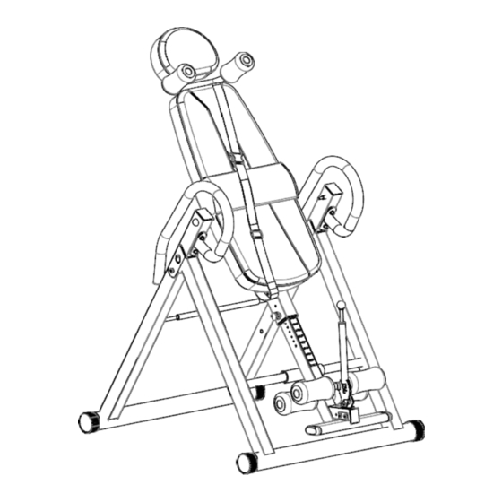
Page 7: Parts Diagram
Parts diagram 7 11 ADJUST TO YOUR HEIGHT SETTING NOTE: Before starting, ensure that the inversion table is at the correct setting to match your height and weight distribution. As each individual body type is different, you will need to find your own height setting. NOTE: It is recommended that someone be with you during inversion. -
Page 8: Step 1 - Base Frame Assembly
Step 1 – Base Frame Assembly Stand up the base of the machine by separating the frames as shown above. Pull the Rear Front Frames as far apart as possible from each others and find the pin holes. Then insert the Ring Pin (21) from inner side Into the holes on the Rear Frames and the front Frame to lock the frames in place. -
Page 9: Step 2 - Handlebar Assembly
Step 2 – Handlebar Assembly THE HANDLEBARS For added convenience and safety, a set of Handlebars (10) (Arm-rest frame) has been added to the inversion table. These Handlebars (10) are located at the top of the Rear Frame (2).The Handlebars (10) are there to help you return to the upright position from any degree of inversion. - Page 10 Step 3 – Backrest Pad Assembly 13.Headrest pad 18.Cross-shape big and flat head screw 5.Backplane 27.Backplane holder Backrest Pad installation: Put the Head restpad(13)to the backrest holder(27),use the(18)M6 cross-shape big and fathead screw insert it. Put the Backplane ( 5 ) stick to the backrest holder, also use the the (18) M6 cross-shape big and fat head screw insert it.
- Page 11 Assemble and lock 4 iron sheets on the Z-shape holder (12) and iron sheet on the side of backplane holder(27) tightly with inner hexagonal screws (16)flat gaskets(15) and lock- nuts(17).
- Page 12 Step 4 – Height Adjustment tube and Ankle Holder Insert the steel pipe of lower foot pressing tube(8) into the big hole in the height adjusting holder, keep two sides the same length, fix lower foot pressing tube on the height adjusting holder(6) with inner hexagonal screws (16) and then put 4 foams rollers (11)into two sides respectively.
- Page 13 Step 5 – Height adjusting holder, back plane holder, shoulder pad U-shape Tube assembly Insert the height adjusting tube(6)into the backplane holder(27),plug into the corresponding hole with the pulling pin(22) and bolt of pulling ring(21)according to the requirement of height and tighten them. Insert the shoulder pad U-shape tube (28) into the hole in the upper of the back Plane holder(27), tighten with flat gaskets (15) and lock-nuts (17), and then insert foams (11) into the Tube on both sides of the shoulder pad U-shape tube(28).
- Page 14 Step 6 – Hand bar frame and waist cushion assembly A. Tighten2 holes in the upper middle of the pedestal(1/2)and Arm-rest frame(10), attach the waist cushion(29) to the velro below the backplane(27). B. Plug two bolts of pulling ring (21) into the hole in the height adjusting tube, you can plug out 2 bolts of pulling ring (21) and fold them when not in use, which takes up no space at all.
- Page 15 Warm Up Quadriceps Stretch With one hand against a wall for balance, reach behind you and pull your right foot up. Bring your heel as close to your buttocks as possible. Hold for 15 counts and repeat with left foot up. Inner Thigh Stretch Sit with the soles of your feet together with your knees pointing outward.
Need help?
Do you have a question about the IVT-6314-RD-BK and is the answer not in the manual?
Questions and answers