Table of Contents
Advertisement
Quick Links
Advertisement
Table of Contents

Related Manuals for Everfit BFK EASY SLIM MULTIFIT


Summary of Contents for Everfit BFK EASY SLIM MULTIFIT
- Page 1 INSTRUCTION Ed : 02/17 Rev : 00...
-
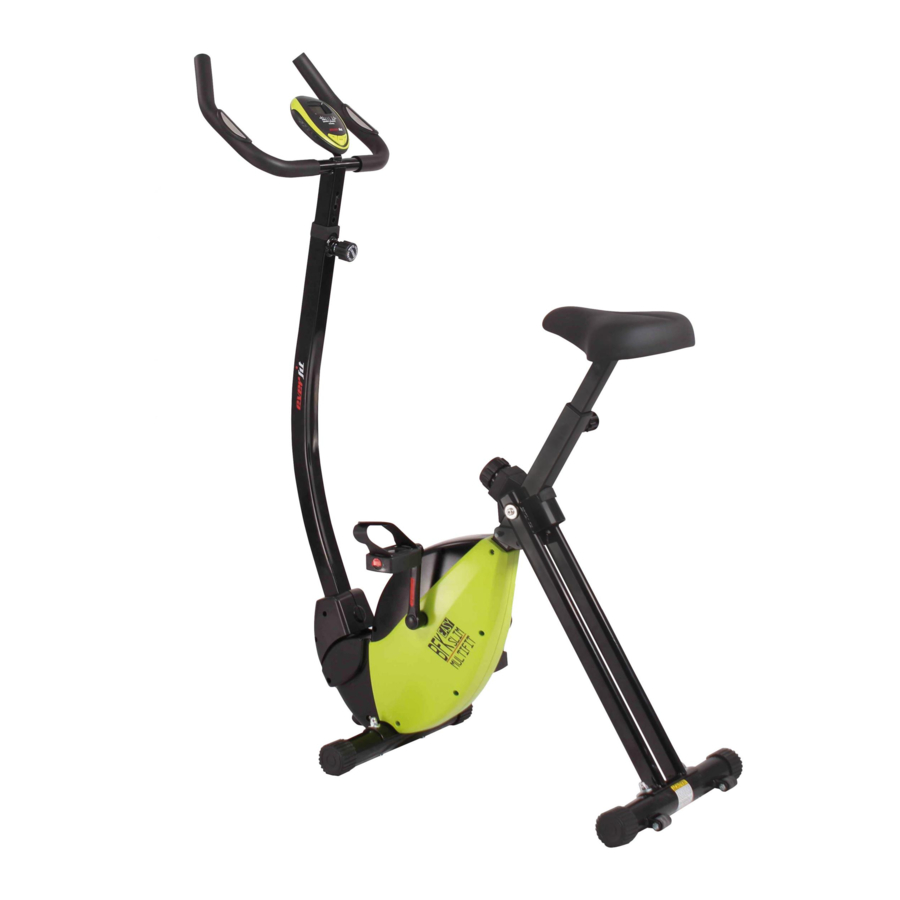
Page 2: Product Overview
PRODUCT OVERVIEW Handlebar Meter Pulse Sensor Adjustment Knob Upright Tension Knob Seat Left Pedal Left Front Cover Left Crank End Cap End Cap Front Stabilizer Transport Wheel Rear Stabilizer Left Chain Cover THEFOLLOWINGTOOLS ARE INCLUDED Wrench: FOR ASSEMBLY Allen Wrench (5mm) w/ Screwdriver:... -
Page 3: Hardware Identification Chart
HARDWARE IDENTIFICATION CHART Figure Description Carriage Bolt (M8 x 1.25 x 60mm) Screw, Round Head (M6 x 1 x 12mm) Acorn Nut (M8 x 1.25) Arc Washer (M8) Adjustment Knob Pull Pin... -
Page 4: Assembly Instruction
ASSEMBLY INSTRUCTION ASSEMBLY INSTRUCTION Place all parts from the box in a cleared area and position them on the floor in front of you. Remove all packing materials from your area and place them back into the box. Do not dispose of the packing materials until assembly is completed. - Page 5 ASSEMBLY INSTRUCTION ASSEMBLY INSTRUCTION STEP 4: Attach the Seat (7) to the Seat Post (6) with Nylock Nuts (M8) (73) and Washer (M8) (95). Insert the Seat Post (6) into the Main Frame (1) and secure with the Adjustment Knob (33). NOTE: 1.
- Page 6 ASSEMBLY INSTRUCTION ASSEMBLY INSTRUCTION STEP 5: Insert the Meter (17) onto the iron sheet of Handlebar (4), then connecting Meter Transmission Wire (72) and (19). Hand pulse Line STEP 6: Insert the Handlebar (4) into the Rear Frame (3), then secure the Adjustment Knob(33) with the Screw, Round Head (M6 *1* 12mm) (65) the handlebar on the Rear Frame (2) with Hex Head Bolts M6 (80) STEP7: Lock and tight the Left Pedal (37) and Right Pedal (46) on the Left Crank (38) and Right...
- Page 7 OPERATIONAL INSTRUCITONS USING THE FITNESS METER POWER ON: Pedal movement or press the button. S C A N T I M E POWER OFF: Automatically shuts off after four minutes of inactivity. S P E E D P U L S E D I S T A N C E O D O M E T E R C A L O R I E S...
- Page 8 HOW TO INSTALL AND REPLACE BATTERIES Open the Battery Door on the back of the meter. The meter operates with two AAA batteries, the batteries are not included. Refer to the illustration to install or replace the batteries. NOTE: 1. Do not mix a new battery with an old battery. 2.
-
Page 9: Load Adjustment
LOAD ADJUSTMENT To increase the load, turn the 8 Section Adjustment Knob (51) clockwise. To decrease the load, turn the 8 Section Adjustment Knob (51) counterclockwise. There are eight levels for the load adjustment. SEAT ADJUSTMENT Proper seat adjustment is important. Turn the Adjustment Knob (33) to loosen, then pull the Adjustment Knob (33) to release the pin. - Page 10 OPERATIONALINSTRUCTIONS STORAGE • To store the BIKE, simply keep it in a clean dry place. • To avoid damage to the electronics, remove the batteries before storing the BIKE for one year or more. • To move the BIKE, hold the HANDLEBAR and tilt the BIKE onto the Wheels of the Stabilizer at the front.
- Page 11 OPERATIONALINSTRUCTIONS It is the sole responsibility of the user/ owner to ensure that regular maintenance is performed. Worn or damaged components shall be replaced immediately or the BIKE removed from service until repair is made. Keep your BIKE clean by wiping it off with an absorbent cloth after use. UPRIGHT ADJUSTMENT Refer to the illustrations below.
-
Page 12: Product Parts Drawing
PARTSLIST PRODUCT PARTS DRAWING... - Page 13 PARTSLIST PARTS LIST Description Main Frame Rear Frame Hand Rail Handlebar Front Stabilizer Seat Post Seat Rear Stabilizer Left Chain Cover Right Chain Cover Middle Cover Left Front Cover Right Front Cover Lever cover Hollow Cap Foam Cap Meter Handrail Foam Hand pulse Line Pulse Sensor Sensor Bracket...
- Page 14 PARTSLIST Left Crank Flywheel V-Ribbed Belt (230J) V-Ribbed Belt (240J) Pulley w/ Shaft Pull Pin Bearing Housing cover Right Pedal Right Crank Pulley Shaft Pulley Lever Magnetic Bracket 8 Section Adjustment Knob Spring Sensor Ball Bearing (6000Z) Tension Bracket Carriage Bolt M8X60 Hex Head Bolt M6X45 Hex Head Round Bolt M8X20 Eye Bolt M6...
- Page 15 PARTSLIST C Ring Φ17.0 Ball Bearing (6003ZZ) C Ring Φ10 Wave Spring Washer S17 Spring Washer (M8) Washer M8 Large Washer (ø8.2 x ø25 x 2mm) Magnet Nut M10 Bolt, Round Head Washer M4X10 Nut M10 Washer M5 Idler Shaft Ball Bearing (6200ZZ) Idler Shaft Sleeve...
- Page 16 GARLANDO SPA Via Regione Piemonte, 32 - Zona Industriale D1 15068 - Pozzolo Formigaro (AL) - Italy www.everfit.it - info@everfit.it...
Need help?
Do you have a question about the BFK EASY SLIM MULTIFIT and is the answer not in the manual?
Questions and answers