Table of Contents
Advertisement
Quick Links
Astro-Physics
GTO Servo Drive System
Operating Instructions
Astro-Physics Command Center
Non-ASCOM
Windows
Program
Non-ASCOM
Mac
Program
Model GTOCP4
AP GTOCP4
Servo Control Box
AP GTO Keypad
January 2024
ASCOM
AP
V2 Driver
Multiple
ASCOM
Client
Applications
*
Windows Computer
with ASCOM
Planetarium
Software
ACP on iPad
Auto-guider Inputs
from
Guide Camera
Apple, Android
& Windows
Mobile Devices
via
Direct or
Network Wi-Fi
* connector layout may vary
Advertisement
Table of Contents

Related Manuals for ASTRO-PHYSICS GTOCP4


Summary of Contents for ASTRO-PHYSICS GTOCP4
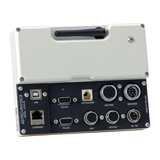
- Page 1 Astro-Physics GTO Servo Drive System Model GTOCP4 Operating Instructions ASCOM Astro-Physics Command Center V2 Driver Windows Computer with ASCOM Planetarium Multiple Software ASCOM Client Applications AP GTOCP4 Non-ASCOM Windows Servo Control Box Program ACP on iPad Non-ASCOM Program Auto-guider Inputs...
-
Page 2: Table Of Contents
Astro-Physics GTO Servo Drive System Model GTOCP4 CONTENTS ABOUT THIS MANUAL - JANUARY 2024 GTO CONTROL BOX- MODEL GTOCP4 -YOUR MOUNT’S BRAIN ENVIRONMENTAL CONSIDERATIONS GTO SERVO DRIVE SYSTEM SPECIFICATIONS GTOCP4 CONTROL BOX - LAYOUT AND FEATURES Receptacles 10-pin Receptacle for Servo Motors... - Page 3 Keypads Using v5.xx Firmware Setting Up the Astro-Physics ASCOM V2 Driver Workflow When Using the AP ASCOM V2 Driver with Third-party Software The Astro-Physics Command Center - Standard & Pro Versions Some APCC Thoughts Setting Up the Astro-Physics Command Center Workflow When Using APCC &...
- Page 4 How to Test an Auto-guider Port TROUBLESHOOTING, TIPS AND SUPPORT Troubleshooting and Tips Additional Support APPENDIX A: GTOCP4 AND GTOCP5 SOFTWARE UPDATES AP GTO Utilities APPENDIX B: POWER SPECIFICATION TABLES Power Specifications - Mach1GTO, 400GTO and 600EGTO Power Specifications - 900GTO (All) and 1200GTO (shipped prior to 2011) (1200GTOs - Ser.
-
Page 5: About This Manual - January 2024
ABOUT THIS MANUAL - JANUARY 2024 Up until the middle of 2011, the Astro-Physics GTO Servo Motor Drive System was described in a small section toward the end of each individual mount manual. As time has passed and more options have become available - both in terms... -
Page 6: Gto Control Box- Model Gtocp4 -Your Mount's Brain
There are three major sub-systems to the GTO Servo Drive: The GTOCP4 Control Box This is the real “brain” of your mount. Please try to understand this from the outset. Your mount is NOT controlled by the keypad or by your computer. They merely serve as input devices and convenient interfaces for you, the user. -
Page 7: Environmental Considerations
● If you are mounting a GTOCP4 on the RA axis of the 900 or 1200 mount, you may want to consider using our Pier/ Tripod Control Box Adapter (CBAPT) if you feel that the angle of the control box is too horizontal to allow adequate dew runoff. -
Page 8: Gto Servo Drive System Specifications
(Except: 400GTO and 600EGTO which had 3.2:1 spur gear reduction and either a 19.8:1 or 32:1 gear head on the motor). Servo Motor Control Box GTOCP4 Control Box, removable. Optional GTO Keypad to control all mount functions. Includes extensive databases and tour Hand-held computer features in a simple, intuitive interface. -
Page 9: Gtocp4 Control Box - Layout And Features
Computer with a planetarium program or observatory control software. The "The Astro-Physics Command Center (APCC)" is highly recommended. Astro-Physics also has a fully supported ASCOM V2 Driver available. A more detailed listing of software is in the "Controlling Your GTOCP4 Mount" on page 39. In addition, see the Website’s... -
Page 10: Receptacles
There is no on-off switch on the GTOCP4, although on-off switches are found on most power supplies. We recommend that you connect all of your cables to the GTOCP4 Servo Control Box before applying power, whether from a power supply or from a battery. -
Page 11: Auto-Guider Port Receptacle
Auto-guider Port Receptacle This receptacle interfaces with the RJ-11-6 modular plug of an auto- guider cable, purchased separately or as part of a CCD Imaging AutoGuider Port Camera or Auto-guider. The port uses the industry standard ST4 pinout as shown at right. Generally speaking ST-4 is considered a RJ-11-6 Receptacle legacy an outdated approach to guiding. -
Page 12: Removing And Installing The Gtocp4 Control Box
The GTOCP4 is secured into the dovetail (or bracket) by two #8-32 thumbscrews (or two #8-32 set-screws). To remove the GTOCP4 simply loosen these thumb-screws (or set screws) and then tilt and lift the box free from the dovetail connection. Reverse the procedure to install. -
Page 13: Communicating With Your Mount
Remote observatories will generally require a computer or an IP addressable server in the remote observatory itself, along with a high-speed internet connection for communication with your home computer. The Ethernet and WiFi discussed below will prove helpful. However, such complete long-range solutions are beyond the scope of Astro-Physics to supply or support. -
Page 14: Rs-232 Serial Port
internal FTDI chipset in the CP4/5 remains powered, it will almost never crash. In addition, the chip is uniquely serialized, so that every time you connect to the CP4/5 it will be found on the same COM port, preventing COM port hunts. The port itself is sturdy and will provide excellent connector retention after many, many connections. -
Page 15: Network Ethernet Port
“old days.” Network Ethernet Port The CP4/5 introduces Ethernet connectivity to the Astro-Physics GTO Servo System. Ethernet is the fastest communication method between the mount and the computer, operating magnitudes faster than serial and USB, and even slightly outpacing the WiFi. -
Page 16: Connect Your Gtocp4 Or Gtocp5 Via Ethernet
GTOCP4 and GTOCP5 Control Boxes -these files are useful for both. The Default IP Address is what the CP4/5 was shipped with, but since it can be changed from the default to something else, we offer other options below for recovering... -
Page 17: Summary Network Connection Diagrams
Summary Network Connection Diagrams The following diagrams provide an easy visual summary of the connection possibilities for your GTOCP4/5 using either Ethernet, WiFi or both in several configurations. They are not a substitute for the text, but should provide help for those who are not well versed in networking specifics. -
Page 18: Do The Math Yourself
For a CP5, the factory default Hostname is GTOCP5-X, where X is the serial number of the GTOCP5 without leading zeros. For a CP4, it is GTOCP4-X with X again being the serial number. The hostname is user-configurable. NOTE: Earlier CP4/5 boxes (shipped before early spring, 2021) will use an underscore instead of the hyphen: I.e. GTOCP5_X To use the hostname as a URL and not perform a browser search, use the form http://GTOCP5_X and press enter. -
Page 19: Set Ethernet Parameters Using Ap Gto Utilities
Set Ethernet Parameters Using AP GTO Utilities Astro-Physics now provides an easy to use utility to handle most of your CP4 control box setup tasks, including settings for Ethernet and WiFi. You can see more about the AP GTO Utilities from our software update page https://www.astro-physics.com/software-updates/. -
Page 20: Network Wifi Connection
Term Definition Network / LAN / • A network is a connected set of clients, sometimes with routers and servers. A network can be Subnet anything from a computer wired directly to a CP4/5, to a CP4/5 connected to a router that can access other routers and computers, and possibly the entirety of the internet. -
Page 21: Cp4/5 Hot Spot (Access Point) Configuration
Your CP4/5 has the capability of acting as a WiFi access point (aka Hot Spot). You can change the settings through the AP GTO Utilities found at https://www.astro-physics.com/software-updates/. Hot Spot enabled is the default factory setting for new control boxes. The... -
Page 22: Network (Station) Configuration
The default password that we have provided during our initial programming will be: Xadmin12345 where again, the X represents the numeric portion of the serial number without leading zeros. For the GTOCP4 with the serial number CP4-2468, the password would be: 2468admin12345. For a CP5 with serial number CP5-4321, it would be: 4321admin12345 When the WiFi connection is established, you can do things like control the CP4/5 using telescope control apps. -
Page 23: Change Your Wifi Settings
Change Your WiFi Settings As mentioned earlier, your CP4/5 default WiFi setting was programed at Astro-Physics to be a Hot Spot. In order to configure your WiFi connection to Network Mode via a wireless device, follow the procedure below. You may also make these changes from an Ethernet connection as described in section "Set Ethernet Parameters Using AP GTO Utilities"... -
Page 24: Updating Your Cp4/5 With New Firmware
Note that there are two Astro-Physics forums. PLEASE use the ap- forum for all things mount related. -
Page 25: Encoder Operation And Periodic Error Management
GTOCP3 Servo Control Box. The Precision Encoder System used the GTOELS box. The Absolute Encoder System used the GTOAE box. The GTOCP4/5 control boxes combine the functions of the two separate boxes into a much more efficient, and much faster package. -
Page 26: Gtocp4 And Absolute Encoders (1100Gto And 1600Gto)
GTOCP4 and Absolute Encoders (1100GTO and 1600GTO) 1100GTO and 1600GTO mounts that are equipped with Absolute Encoders do not require a separate control box for operation. The full functionality of the previous GTOAE box has been incorporated into the CP4. This dramatically increases the processing speed of operations, as well as eliminating connection cables. -
Page 27: For 3600Gtope Owners Only: Installation, Settings And Operating Instructions For The Limit Switch System (36Lss) And Precision Encoder System (On The 3600Gtope), Dated March 27, 2013
Switch System (36LSS) and Precision Encoder System (on the 3600GTOPE), dated March 27, 2013 This document has not yet been updated for the GTOCP4 and the present cable arrangement. Please note the following: the vast majority of the information is still relevant and current. Simply adapt the procedures by substituting the GTOCP4 for all functions. -
Page 28: Understanding The German Equatorial Servo Logic
The discussion that follows will address several areas of the GTOCP4’s control logic and hopefully tie those areas together. -
Page 29: The Role Of Time And Location Data In The Servo System
Park positions can be handy, but they are not a requirement. With the Astro-Physics system, think of "park" as a state where the drive motors are de-energized - not a "place" where the mount goes. -
Page 30: Understanding The Auto-Guider Port Inputs Vs Timed Guide Moves
"pulse guide" for guiding by commands as opposed to guiding via autoguider relays. This has led to quite a bit of confusion for Astro-Physics customers. (Other mounts could not use Ray's PulseGuide™, so it was not an issue for anyone else.) It isn't really a problem as long as YOU know the difference and don't confuse the two. -
Page 31: A Brief Introduction To The Astro-Physics Command Language
A Brief Introduction to the Astro-Physics Command Language The key to all operations of the Astro-Physics GTO Servo System is the command language. This language is a collection of simple ASCII (text) commands that provide all of the necessary information for the mount to slew to the target you have selected at the slew rate you have chosen. -
Page 32: The 360° Right Ascension Axis
So for us, it made a lot of sense to allow the mount to simply keep tracking past the meridian. With that in mind, we did not include any sort of mechanical stops. The Right Ascension of an Astro-Physics mount can... -
Page 33: The Concept Of "Pier Side" As It Relates To The Servo
ASCOM as well. Pier side gets confusing because the correctly reported pier side can differ from what your eyes are telling you if you look at the mount. The Astro-Physics reference Park 1 position is the classic example of this. -
Page 34: How Goto Slews Are Performed
Safety Slew Logic Safety Slew Logic is designed into the GTOCP4 Control Box firmware and functions with all of our GoTo mounts. Its purpose is to protect your scope from a possible crash into the pier when slewing out of some counterweight up positions. -
Page 35: Tracking Past The Meridian
It is even possible that a three part slew may take place if you are slewing from a counterweight up position and into another counterweight up position. Having this firmware logic in the GTOCP4 control box means that it will work regardless of whether you are using computer software or the keypad to control your mount. -
Page 36: Apcc Meridian Tracking Limits
Meridian tracking limits can also be used to create a safe zone around your pier if it interferes with even reaching the zenith, similar in a way to the safe zone in the Astro-Physics GTO keypad. The keypad's safe zone, however, is a GoTo slew limit, rather than a tracking limit. -
Page 37: Mechanical Limit Switches
Encoder System (AE). Its original incarnation used a separate box like the ELS (above), but for obvious reasons, it was called the GTOAE box. All of the functionality and then some from the AE box is now in the GTOCP4/5. The absolute positional accuracy of the AE system allowed the establishment of home and limits that were based on encoder positional readings, and that eliminated the need for mechanical switches. -
Page 38: Keypad Limits
Keypad limits were added as a further safety measure for keypad users and for people using control devices that cannot use APCC or the AP V2 ASCOM Driver. See the section "Controlling Your GTOCP4 Mount" on page 39. They also... -
Page 39: Hard Limits
If your control software does not include the ability to set meridian delay, you can simply turn the limits on or off from the CP4/5's browser web page. This would be useful for DSLR imagers controlling the mount with Sky Safari, as an example. We DO NOT advise using Keypad Limits in firmware versions VCP4-P02-05 and earlier. Please keep your GTOCP4 firmware current!! 5. -
Page 40: Controlling Your Gtocp4 Mount
The real brains of the Astro-Physics GTO Servo Control System are in the GTOCP4 control box. Simply think of your keypad or computer as being an input device for the GTOCP4. If you understand this from the start, you will always have a better concept of how things work, and you will be less likely to make operator errors. -
Page 41: What Is Meant By "Initialization
Re-Calibrate function which has elements of both control and GoTo / Move. Periodic error correction can be accomplished as simply as using the GTOCP4 along with a device like the keypad to record and then play back a simple, stored PE curve. The pinnacle of Periodic Error Management for non-encoder mounts is the highly sophisticated "PEMPro™... -
Page 42: Using Your Keypad And Pc In Shared Harmony
In addition, the keypad is not able to constantly poll the mount. It can poll the mount whenever instructed to do so, and can poll using any command in the Astro-Physics Command set, but it can't just poll at will. Consequently, there are some rules that need to be observed for keypads using v4.xx or v5.xx firmware. -
Page 43: Keypads Using V5.Xx Firmware
The above advances in Keypad / computer communication are the reason for our STRONG recommendation to update your Keypad to the version 5.xx firmware as soon as it's available, and to keep your GTOCP4 updated as well. However, if you have additional mounts that have GTOCP3 or earlier control boxes, then it will not be possible to share the v5.xx Keypad with them. -
Page 44: Setting Up The Astro-Physics Ascom V2 Driver
APCC instead of ASCOM V2. One of the first things that must be done is to set up the Astro-Physics V2 ASCOM Driver. This is extremely important, as the settings that you enter will be used to initialize the mount once you power up and connect to the mount with your third-party software. - Page 45 Initialization Setup - Check all the boxes in the top right window. A) Sync Mount Time at initialization - recommended to be checked. B) Set Latitude / Longitude - default is to leave it Checked. C) Enable Mount Tracking on Unpark - under normal circumstances this is usually Checked. D) Set Slew Rate - this may be set as you like.
-
Page 46: Workflow When Using The Ap Ascom V2 Driver With Third-Party Software
You can review it if you wish. Then click OK once or twice and you are done. The Astro-Physics V2 ASCOM Driver is a hub through which all third-party ASCOM compliant software can be connected. Planetarium, camera control, and focusing software, etc. -
Page 47: The Astro-Physics Command Center - Standard & Pro Versions
The Astro-Physics Command Center - Standard & Pro Versions The Astro-Physics Command Center (APCC) adds many features and extended functionality to the control system of the mount and it will act as a serial hub for the use of additional applications. It takes remote operation to the next level with safety and convenience that you won't want to be without. -
Page 48: Some Apcc Thoughts
Much more !!! The APCC Pro version includes the following additional features: ● Highly-sophisticated pointing model and variable tracking for both axes; includes the Astro-Physics Point Mapper (APPM) for automated collection of pointing data. ● Camera options: NINA, Maxim, Sequence Generator Pro, ASCOM camera and SkyX Image Linking camera Add-on (part of APPM). -
Page 49: Setting Up The Astro-Physics Command Center
Setting Up the Astro-Physics Command Center APCC can be as simple or as complex as you wish to make it. This Quick Start guide will only touch upon the Setup of this software. The Help menu will provide more detailed information. Don’t forget to click of the “?”... - Page 50 (up to 100’ or more). USB is an excellent choice if that connection distance is less than 15'. The GTOCP4 uses an industrialized and self-powered USB connector and its robustness will only be limited by the USB of your computer (the weak link).
-
Page 51: Workflow When Using Apcc & The Ap V2 Driver With Third-Party Software
You can review it if you wish. Then click OK once or twice and you are done. The Astro-Physics V2 ASCOM Driver is a hub through which all third-party ASCOM compliant software can be connected. Planetarium, camera control and focusing software, etc. - Page 52 Once the mount is parked disconnect and close the active third-party software. Close APCC. The AP V2 Driver will automatically close. Power down the mount. Important note: If you use APCC, you initialize the mount only through APCC. APCC will override any settings in the AP V2 ASCOM Driver.
-
Page 53: Workflow When Using Theskyx™ With The Ap V2 Driver
Setup Telescope window that you filled out earlier. You can review it if you wish. Then click OK once or twice and you are done. The Astro-Physics V2 ASCOM Driver is a hub through which all third-party ASCOM compliant software can be connected. Planetarium, camera control and focusing software, etc. can be connected to it and operated simultaneously. -
Page 54: Planetarium, Imaging And Observatory Software From Other Vendors
Planetarium, Imaging and Observatory Software from Other Vendors There are a number of planetarium and camera control programs that can be used to control the Astro-Physics GTO Servo System. Many of these use the ASCOM interface and will take advantage of the V2 ASCOM driver mentioned previously. -
Page 55: Workflow When Using Theskyx™ With The Ap V2 Driver
“Setup Telescope” window that you filled out earlier. You can review it if you wish. Then click “OK” once or twice and you are done. The Astro-Physics V2 ASCOM driver is a hub through which all third party ASCOM compliant software can be connected. Planetarium, camera control and focusing software, etc. can be connected to it and operated simultaneously. -
Page 56: Workflow When Using Theskyx™ With Native Drivers
Choose Go to “Telescope” in the menu bar and locate the Telescope Chooser in the drop-down menu. Then select Astro-Physics and the appropriate mount type. See image at right. Connect the computer to the mount using any of the four connection options (USB, Serial, Ethernet or WiFi). -
Page 57: Workflow When Using Mobile Smart Devices
Mobile smart devices will all connect over WiFi. The GTOCP4 ships out from the factory in Access Point mode which means that it will act as a hotspot for your smart device. If you wish to have both the GTOCP4 and Smart device go through a local area network, please see the information in "Station Configuration". -
Page 58: Thoughts Regarding Workflow When Using Devices Other Than Pcs
B) Luminos™ i) Click Observe at bottom of screen. ii) Click Remote Control and then the Connection slider. iii) Scroll down and click Un-Park. iv) Choose and click the correct Park Position. Click Done. After an evening enjoying the stellar marvels: A) SkySafari™... -
Page 59: Pempro™ By Sirius-Imaging
PEMPro™ by Sirius-Imaging (Included with the 1100GTO, 1600GTO and 3600GTO mounts) For a visual observer or an imager who takes short exposures, the native performance of your GTO mount will be without additional periodic error correction. However, those of you who take long exposure images may wish to further refine your mount’s performance. -
Page 60: Auto-Guiding Tips And Notes
AUTO-GUIDING TIPS AND NOTES Auto-guiding is an art. It can be the most complicated, yet most important, part of acquiring images. If it is not mastered, then images can suffer. Anything that you can do to make your auto-guider's job easier is a good thing. Here are some suggestions and things to keep in mind. - Page 61 Observe the DEC gears for rotation at 1x. The direction of rotation should be opposite of the direction observed in step #12. Note any differences from the expected performance for communication with the technical staff at Astro-Physics. If the mount performs as expected, then the issue must lie elsewhere.
-
Page 62: Troubleshooting, Tips And Support
LED at power-up. (The Omega is still a better module!) Amber LED – causes and solutions Encoder Fault. The LED on your GTOCP4 may be amber if there is a problem with the Absolute or Precision Encoder ●... - Page 63 Also, note that the GTOCP4 now also includes a King rate for tracking. This can be accessed through software or V5.xx of the keypad.
- Page 64 If you have any doubts about where this worm and spur gear is in the scheme of things, call Astro-Physics and we will talk you through the procedure to check this. Remember this: Any backlash or looseness in Dec. will NOT cause trailed stars after a slew. That is because the Dec. axis does not move once it gets to its new position, so no trailing is possible.
-
Page 65: Additional Support
Note, however, that GTOCP3 and GTOCP2 boxes do not include Absolute and/or Precision Encoder functions. A GTOCP4 that is configured for encoders will still control a non-encoder mount, and a GTOCP2 or 3 will still control an encoder mount, but without encoder functionality. -
Page 66: Appendix A: Gtocp4 And Gtocp5 Software Updates
The AP GTO Utilities an all-in-one application for managing your GTOCP4 or GTOCP5 Controller (with some capabilities for managing your CP3). It replaces and extends the AP USB/Serial Utilities and provides the following features and benefits: •... -
Page 67: Appendix B: Power Specification Tables
5 amps up to 18 volts at a maximum of 10 amps) Higher amperage supplies should be fused at 7.5 or 10 amps for the mount’s power leads. We do not recommend exceeding a nominal 18V system (i.e. one 12V and one 6V in series.) Never exceed 28V at the GTOCP4's input receptacle! Power Specifications - 900GTO (All) and 1200GTO (shipped prior to 2011) (1200GTOs - Ser. -
Page 68: Power Specifications - 3600Gto
18 volts at a maximum of 10 amps) Higher amperage supplies should be fused at 10 amps for the mount’s power leads. We do not recommend exceeding a nominal 18V system (i.e. one 12V and one 6V in series.) Never exceed 28V at the GTOCP4's input receptacle! -
Page 69: Appendix C: Power Considerations
12.0 volts. It will normally perform best if that voltage pressure is between 12.3 and 16 volts for the smaller mounts, or up to 18 volts for the larger mounts. The GTOCP4 can take electrical pressure up to 28 volts at the power input receptacle. -
Page 70: Batteries
DO use higher voltages – up to 16 to 18 volts – for extremely cold temperatures. ● DO keep an eye on the power LED on your GTOCP4 control box. It bears repeating: The two power supplies that we offer (PS138V15A and PSVPW25A) are excellent choices for virtually all customers with U.S. - Page 71 many batteries marketed as “marine deep-cycle” are actually hybrid designs that are really more for starting than deep discharge. If the battery advertises its cranking power (i.e. CCA or cold cranking amps), then it is a hybrid at best, regardless of what the label says. Marine deep-cycle batteries are suitable for powering your mount, but should not be discharged as deeply as true deep-cycle batteries.
-
Page 72: Results Of Either Inadequate Or Excessive Power
The proliferation of personal mobility devices, or “scooters” has also led to the wide availability of deep-cycle batteries in the 20 Ah to 60 Ah range. Many of these are perfectly suited to the smaller mounts as they can be found in a very wide array of sizes. -
Page 73: Important Considerations For Observatory Installations
OK! So, what happens if you connect to a power supply that delivers too high a voltage? This was much more of a problem in the older GTOCP1, 2 & 3 servo control boxes than in the GTOCP4. As mentioned before, the CP4 can handle 24 volts without damage, and can take up to 28 volts before serious problems arise. -
Page 74: Appendix D: Command Language
APPENDIX D: COMMAND LANGUAGE As with the Firmware Update instructions briefly discussed in "Appendix A: GTOCP4 and GTOCP5 Software UpdateS" on https://www.astro-physics.com/ page 65, this section has been removed to a separate document. It can be found at support/ APPENDIX E: REGULATORY INFORMATION FOR... -
Page 75: Appendix F: Country Codes For Wifi
APPENDIX F: COUNTRY CODES FOR WIFI If you are operating the GTOCP4 in a country other than the United States, locate the appropriate “Country Code” in the table below, and enter it in the Country Code field (per ISO 3166-1, alpha-2) in the Advanced WiFi Settings Web page of the GTOCP4’s built-in web pages. - Page 76 Country Country Code Country Country Code Country Country Code Greece Korea, Dem. Mongolia Peoples Rep. of Greenland Montenegro Korea, Republic of Grenada Montserrat Kuwait Guadeloupe Morocco Kyrgyzstan Guam Mozambique Lao, Peoples Guatemala Dem. Rep of Myanmar Guernsey Latvia Namibia Guinea Lebanon Nauru Guinea-Bissau...
- Page 77 Country Country Code Country Country Code Country Country Code Puerto Rico Svalbard and Virgin Islands, British Jan Mayen Qatar Virgin Islands, US Swaziland Reunion Wallis and Futuna Sweden Romania Western Sahara Switzerland Russian Fed. Yemen Syria Rwanda Yugoslavia Taiwan Saint Helena Zambia Tajikistan Saint Kitts and Nevis...
-
Page 78: Appendix G: Network Protocol License
APPENDIX G: NETWORK PROTOCOL LICENSE The GTOCP4 implements the network protocol stack using Light Weight IP (LwIP): lwIP's License lwIP is licenced under the BSD licence: Copyright (c) 2001-2004 Swedish Institute of Computer Science. All rights reserved. Redistribution and use in source and binary forms, with or without modification, are permitted provided that the following... -
Page 79: Appendix H: Gtocp4 / Mount Personality Codes
APPENDIX H: GTOCP4 / MOUNT PERSONALITY CODES Each GTOCP4 control box is assigned a personality code that allows it to work with given mounts. This personality can be changed if it becomes necessary to switch the control box to a different mount in the future. However, the control box would either have to be returned to us or we can change it remotely.
Need help?
Do you have a question about the GTOCP4 and is the answer not in the manual?
Questions and answers