Table of Contents
Advertisement
Quick Links
Astro-Physics
GTO Servo Drive System
Operating Instructions
Astro-Physics Command Center
Non-ASCOM
Windows
Program
Non-ASCOM
Mac
Program
Model GTOCP4
AP GTOCP4
Servo Control Box
AP GTO Keypad
November 30, 2017
ASCOM
AP
V2 Driver
Multiple
ASCOM
Client
Applications
Windows Computer
with ASCOM
Planetarium
Software
ACP on iPad
Auto-guider Inputs
from
Guide Camera
Apple, Android
& Windows
Mobile Devices
via
Direct or
Network Wi-Fi
Advertisement
Table of Contents
Troubleshooting

Related Manuals for ASTRO-PHYSICS GTOCP4


Summary of Contents for ASTRO-PHYSICS GTOCP4
- Page 1 Astro-Physics GTO Servo Drive System Model GTOCP4 Operating Instructions ASCOM Astro-Physics Command Center V2 Driver Windows Computer with ASCOM Planetarium Multiple Software ASCOM Client Applications Non-ASCOM Windows AP GTOCP4 Program ACP on iPad Servo Control Box Non-ASCOM Program Auto-guider Inputs from Guide Camera Apple, Android & Windows Mobile Devices Direct or AP GTO Keypad Network Wi-Fi November 30, 2017...
-
Page 2: Table Of Contents
COnTenTS About this MAnuAl introduction Gto servo drive systeM specificAtions Gto control box – Model Gtocp4 – your Mount’s brAin Gtocp4 control box - layout and features 10-pin receptacle for servo Motors 10-pin receptacle for Absolute encoders 12-volt locking receptacle... - Page 3 Appendix f: reGulAtory inforMAtion for trAnsMitter Module fcc notice (usA) rf exposure ic notice (canada) ce notice (europe) Appendix G: country codes for Wifi Appendix h: netWorK protocol license lwip's license Appendix i: Gtocp4 / Mount personAlity codes...
-
Page 4: About This Manual
AbOuT ThiS MAnuAl up until the middle of 2011, the Astro-physics Gto servo Motor drive system was described in a small section toward the end of each individual mount manual. As time has passed and more options have become available - both in terms... -
Page 5: Introduction
3. An external input device to interface with the user. the interface that we offer as an optional accessory for the Gto servo system is, of course, the Gto Keypad. in addition, the Gtocp4 control box has the versatility to commu- nicate with just about every kind of electronic device imaginable. this obviously includes personal computers, but now also includes numerous mobile smart devices, with more being developed all the time. - Page 6 -40 degrees f (-40 c). (however, if you plan to use your mount in extreme temperatures and conditions, please contact Astro-physics first.) All of this control and sophistication is accomplished in an incredibly efficient manner. the servo drive system can generally be operated from nominal 12-volt systems, although the larger mounts may benefit from slightly higher voltages.
-
Page 7: Gto Servo Drive System Specifications
(except: 400Gto and 600eGto which had 3.2:1 spur gear reduction and either a 19.8:1 or 32:1 gear head on the motor) servo Motor control box Gtocp4 control box, removable optional Gto Keypad to control all mount functions. includes extensive databases and tour hand-held computer features in a simple, intuitive interface. -
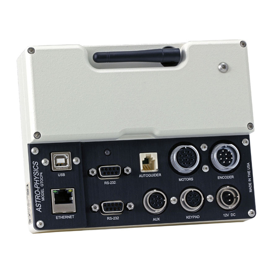
Page 8: Gto Control Box - Model Gtocp4 - Your Mount's Brain
10-pin Receptacle for Absolute Encoders the Gtocp4 incorporates the functionality of both the GtoAe and Gtoels into its design, thus eliminating the need for these secondary boxes when using the 1100Gto and 1600Gto mounts with Absolute encoders or the 3600Gto with precision encoders. -
Page 9: 12-Volt Locking Receptacle
Gtocp4, although on-off switches are found on most power supplies. We recommend that you connect all of your cables to the Gtocp4 servo control box before applying power, whether from a power supply or from a battery. -
Page 10: Choosing Your Communication Interfaces
3. the Gtocp4 has a built in web interface that can be accessed by any browser or via our ethernet-Wifi poll utility. Among other things, this is by far the best way to perform software upgrades to the control box. -
Page 11: Rs-232 Ports
Gtocp4 remains powered, it will almost never crash, and it is able to recover when your computer’s usb develops indigestion. -
Page 12: Ethernet Port
Keyspan. these are still fine adapters, but we are now recommending and selling adapters from ftdi. A primary reason for this change is that the Gtocp4’s on-board usb serial uArt is also by ftdi. this way, you need only a single driver to work with all of your usb to serial applications. - Page 13 WpA2-Mixed-psK (personal). configuration of the Wifi is most easily done from the web pages built into the Gtocp4. it is probably simplest to do this the first time from the ethernet based web pages described above. however, it can also be done pretty easily using the default Access point mode as described below under Getting started.
-
Page 14: More Information On Ip Addresses For Uploading New Software
5. in the browser’s url address bar, enter the following ip address: 172.31.0.1 and then the equivalent of “enter” this will bring up the Gtocp4 Main Web page just like the ethernet version. from this page, you can move on to the change network connection or Advanced Wifi pages. -
Page 15: Ethernet And Wifi Best Practice Recommendations
"server" mode if it is not assigned an IP address after a timeout period. Per IEEE standards, the switch to server mode will take place after more than 30 seconds, so you may need to be patient if waiting to use the GTOCP4 as a peer-to-peer device when set to "both."... -
Page 16: Removing And Installing The Gtocp4 Control Box
Removing and Installing the GTOCP4 Control Box An important part of the design philosophy at Astro-physics is to use a modular approach to the system components. in the rare event of a failure, many components can be easily removed for repair, replacement or temporary swap-out. this modular philosophy is exemplified by the Gtocp4 control box and its predecessors. -
Page 17: Gtocp4 And Absolute Encoders
Gtocp4’s second rs-232 serial port or through the usb connection (which is another form of serial port). A straight-through serial cable was provided with the mount and can be used for this purpose. -
Page 18: Gtocp4 And Precision Encoders
Astro-Physics Absolute Encoder Mini Utility if you don't have the Astro-physics command center (Apcc), you can use the Astro-physics Absolute encoder Mini utility (ApAeMiniutil) to turn your precision encoders on and off. it does not have any additional capability. please contact Astro-physics if you need the utility. -
Page 19: Controlling Your Gto Mount
Astro-physics Gto servo control system are in the Gtocp4 control box. simply think of your keypad or computer as being an input device for the Gtocp4. if you understand this from the start, you will always have a better concept of how things work, and you will be less likely to make operator errors. -
Page 20: Gto Keypad Operation
Gtocp4 servo control box. some of these, like the Astro-physics command center (Apcc), the Astro-physics v2 AscoM driver, and the Gto Keypad will provide All of the “primary Mount control functions,” the “Goto and Move functions,”... - Page 21 ● the Ap v2 AscoM driver takes advantage of the full set of Astro-physics servo commands, many of which were developed specifically for either the driver or for Apcc. since these new commands are not being published, the native drivers found in other software will be limited to the older set of published commands.
-
Page 22: The Astro-Physics Command Center (Apcc)
The Astro-Physics Command Center (APCC) the Astro-physics command center (Apcc) adds many features and extended functionality to the control system of the mount and it will act as a serial hub for the use of additional applications. it takes remote operation to the next level with safety and convenience that you won't want to be without. -
Page 23: Some Apcc Thoughts
Much more !!! the APCC Pro version also includes the following: ● highly sophisticated pointing model and variable tracking for both axes including the Astro-physics point Mapper (AppM) for automated collection of pointing data. please keep an eye on the Apcc page of the website and the ap-gto users group for updates and details. -
Page 24: Planetarium, Imaging And Observatory Software From Other Vendors
Planetarium, Imaging and Observatory Software from Other Vendors there are a number of planetarium and camera control programs that can be used to control the Astro-physics Gto servo system. Many of these use the AscoM interface and will take advantage of the v2 AscoM driver mentioned previously. -
Page 25: Pempro™ By Sirius-Imaging
PEMPro™ by Sirius-Imaging (included with the 1100GTO, 1600GTO and 3600GTO mounts) for a visual observer or an imager who takes short exposures, the native performance of your Gto mount will be without additional periodic error correction. however, those of you who take long exposure images may wish to further refine your mount’s performance. -
Page 26: Pulseguide™ By Sirius-Imaging
PulseGuide™ is a stand-alone Windows (xp, vista, Windows 7, Windows 8 and 8.1 and Windows 10) based utility that provides complete remote control of all Astro-physics Gto mounts. "stand-alone" means that it does not operate through AscoM, but via direct control of the mount. it was originally developed to provide the keypad's functionality from a computer. -
Page 27: Understanding The German Equatorial Servo Logic
With the Astro-physics system, think of "park" as a state where the drive motors are de-energized - not a "place" where the mount goes. -
Page 28: The Role Of Time And Location Data In The Servo System
Gtocp4 control box means that it will work regardless of whether you are using computer software or the keypad to control your mount. -
Page 29: The Concept Of "Pier Side" As It Relates To The Servo
AscoM as well. pier side gets confusing because the correctly reported pier side can differ from what your eyes are telling you if you look at the mount. the Astro-physics reference park 1 position is the classic example of this. -
Page 30: Tracking Past The Meridian
Meridian tracking limits can also be used to create a safe zone around your pier if it interferes with even reaching the zenith, similar in a way to the safe zone in the Astro-physics Gto keypad. the keypad's safe zone, however, is a Goto slew limit, rather than a tracking limit. - Page 31 Astro-physics mounts. both the keypad and the earlier pulseGuide program provided the ability to work beyond the meridian.
-
Page 32: Autoguiding Tips And Notes
AuTOGuiDinG TiPS AnD nOTeS Autoguiding is an art. it is the most complicated, yet most important, part of imaging. if it is not mastered, then images will suffer. Anything that you can do to make your autoguider's job easier is a good thing. here are some suggestions and things to keep in mind. - Page 33 14. observe the dec gears for rotation at 1x. the direction of rotation should be opposite of the direction observed in step #12. 15. note any differences from the expected performance for communication with the technical staff at Astro-physics. if the mount performs as expected, then the issue must lie elsewhere.
-
Page 34: Troubleshooting, Tips And Support
TrOubleShOOTinG, TiPS AnD SuPPOrT Troubleshooting and Tips Additional troubleshooting questions are in the individual mount manuals and in the Gto Keypad manual. some of the issues discussed in the keypad manual also relate to mount communication issues whether you use the keypad or control the mount with a planetarium program or PulseGuide™. - Page 35 Gralak’s PulseGuide™ will allow you to dial in an exact tracking rate for any part of the sky. the Astro-physics command center (Apcc) includes tracking and pointing correction based on calculations from atmospheric refraction all the way up to sophisticated real-world models based on plate-solve data for your specific instrument package.
- Page 36 however, the r.A. axis Will cause trailed stars after a slew if the spur gear is loose. that is because this axis must move at the sidereal rate immediately after getting to the new position. if the spur gear is loose on the worm shaft, it will turn slowly at the sidereal rate without imparting this motion to the worm itself (because it is slipping).
-
Page 37: Additional Support
My GTOCPx Control box does not appear to be working properly. Can i use the control box from my other Astro-Physics mount with the mount that is having problems? the answer depends on which model your other Astro-physics mount is. the Gtocp4, Gtocp3 and / or Gtocp2 control boxes from your Mach1GTO, 900Gto, 1100Gto, 1200Gto or 1600Gto mount can all be interchanged. the interchange works in either direction between any of these five mounts. note, however, that Gtocp3 and Gtocp2 boxes do not inclulde Absolute and/or precision encoder functions. -
Page 38: Appendix A: Power Specification Tables
APPenDix A: POWer SPeCiFiCATiOn TAbleS Power Specifications - Mach1GTO, 400GTO and 600EGTO power consumption 0.3 to 0.5 amps at 13.8 volts tracking; 1.0 to 2.2 amps at 13.8 volts - both motors slewing at top speed of 1200x. (Gto Keypad connected; no load; room temperature) power requirements 12.0 to 16 volts dc at a minimum of 5 amps continuous recommended. -
Page 39: Appendix B: Power Considerations
18 volts for the larger mounts. if the pressure exceeds 19 to 20 volts, you may begin to generate heat buildup in the Gtocp4 control box as the unit’s voltage regulator must dissipate more and more excess energy as heat. -
Page 40: Batteries
Astro-physics mounts that are currently in production. - Page 41 choice as true deep-cycle batteries, but are often much less expensive than true deep-cycle batteries. note also that many batteries marketed as “marine deep-cycle” are actually hybrid designs that are really more for starting than deep discharge. if the battery advertises its cranking power (i.e. ccA or cold cranking amps), then it is a hybrid at best, regardless of what the label says.
-
Page 42: Results Of Either Inadequate Or Excessive Power
● the power led on the Gtocp4 turns from red (normal) to amber (motor stall or safe mode) or goes out completely. When the power light changes color to amber, the servo shuts down and quits trying to drive the motors. A note of caution: the amber light does not necessarily signify low voltage from your power supply. -
Page 43: Important Considerations For Observatory Installations
18 volts (large mounts) or over 16 volts (smaller mounts), you should periodically check the Gtocp4 to be sure it is not overheating. Warm to the touch is oK. too hot to touch continuously is too hot! ●... -
Page 44: Appendix C: Gtocp4 Software Update
Gtocp4, and connect the ethernet (i.e. cat6) cable to the Gtocp4 on one end, and to your computer or a router or network switch (port) on the other end. -
Page 45: Download Using A Browser
Advanced ethernet settings window to reset the dhcp Mode to either “client” or “both.” A power cycle of the Gtocp4 will then be required for the change to take effect – power off – wait a few seconds – power ... - Page 46 Gtocp4. use of Google chrome may be a little more difficult because chrome is optimized for the World Wide Web, and may skip any search for local hosts.
- Page 47 “part 1” software while it over-writes the old part 2 software with the new. “part 2” contains the mount control functions. At this time, the front panel led on the Gtocp4 will begin to blink rapidly to indicate that the mount functions are not active.
-
Page 48: Appendix D: Rs-232 Command Language For Gtocp3 And Gtocp4 Servo Control Boxes
Gtocp3 control box and look for a label on one of the large, square chips. ● the chip version can be found in several places in the Astro-physics v2 AscoM driver. in the setup telescope window, click the “check port” button. Assuming you have a good connection, a popup window will appear saying: “Mount found! firmware rev: v2 “... -
Page 49: Telescope Motion
Command: :Sl hh:MM:SS# response: “1” sets the current local time. command may be issued in long or short format regardless of whether long format has been selected. Command: :SC MM/DD/yy# response: 32 spaces followed by “#”, followed by 32 spaces, followed by “#” sets the current date. note that year fields equal to or larger than 97 are assumed to be 20th century, year fields less than 97 are assumed to be 21st century. - Page 50 if the horizon check is turned on, and the desired object is below 0 degrees altitude. (8 trailing spaces before “#”, 32 total characters plus “#”) slew to the most recently defined rA and dec coordinates in rA-dec mode, or most recently defined Alt and AZ coordi- nates in Alt-AZ mode. slewing is performed at the currently selected slew rate. if the horizon check is turned on, and the object is below the horizon, this will be stated, and no slewing will occur.
- Page 51 Command: :rT0# :rT1# :rT2# :rT9# response: (none) this command selects the tracking rate. it selects lunar (:rt0#), solar (:rt1#), sidereal (:rt2#), or zero (:rt9#). the sidereal rate is assumed as a default by the motor drive if nothing is specified. this command has no effect on the use of the n-s-e-W buttons.
-
Page 52: Position
Command: :FM# response: (none) equatorial fork: this command is the manufacturing default, which eliminates the meridian flip. German equatorial: this command is intended for software developers. it turns off the meridian flip and makes a German equatorial mount behave like a fork mount. it is not to be used by individuals without slewing safeguards. it is mainly intended as a tool for writers of mount control software to implement slewing past the meridian during imaging, and then only with the proper limits and controls to prevent the telescope from slewing into the pier or other abnormal motions. -
Page 53: Miscellaneous
Gtocp1 and Gtocp2 servo control boxes for infor- mation on issues with this command on earlier chips. note: This command did not work properly until the v version chip. Communicating with Your Mount When Writing Your Own Programs note to programmers developing commercial programs: please contact Astro-physics for information regarding the AscoM driver. this driver is the most effective way to control... - Page 54 :po# command to do so. support please note that Astro-physics does not support any programs that you write yourself or any program distributed as an after- market product. please contact the manufacturer for questions relating to after-market programs.
-
Page 55: Appendix E: Command Language / Troubleshooting Update
(none) since most planetarium software and the Astro-physics keypad software all perform their own horizon check calculations, this command is rarely activated. the horizon check was included in the command set for people who may be writing their own control software. -
Page 56: Appendix F: Regulatory Information For Transmitter Module
APPenDix F: reGulATOry inFOrMATiOn FOr TrAnSMiTTer MODule FCC notice (uSA) this equipment has been tested and found to comply with the limits for a class b digital device, pursuant to part 15 of the fcc rules. these limits are designed to provide reasonable protection against harmful interference in a residential installation. -
Page 57: Appendix G: Country Codes For Wifi
APPenDix G: COunTry CODeS FOr WiFi if you are operating the Gtocp4 in a country other than the united states, locate the appropriate “country code” in the table below, and enter it in the country code field in the Advanced Wifi settings Webpage of the Gtocp4’s built-in web pages. - Page 58 Country Country Code Country Country Code Country Country Code Greece Korea, dem. Mongolia peoples rep. of Greenland Montenegro Korea, republic of Grenada Montserrat Kuwait Guadeloupe Morocco Kyrgyzstan Guam Mozambique lao, peoples Guatemala dem. rep of Myanmar Guernsey latvia namibia Guinea lebanon nauru Guinea-bissau lesotho nepal Guyana...
- Page 59 Country Country Code Country Country Code Country Country Code puerto rico svalbard and virgin islands, british Jan Mayen qatar virgin islands, us swaziland reunion Wallis and futuna sweden romania Western sahara switzerland russian fed. yemen syria rwanda yugoslavia taiwan saint helena Zambia tajikistan saint Kitts and nevis Zimbabwe tanzania...
-
Page 60: Appendix H: Network Protocol License
APPenDix h: neTWOrK PrOTOCOl liCenSe the Gtocp4 implements the network protocol stack using light Weight ip (lwip): lwiP's license lwip is licenced under the bsd licence: copyright (c) 2001-2004 swedish institute of computer science. All rights reserved. redistribution and use in source and binary forms, with or without modification, are permitted provided that the following conditions are met: 1. -
Page 61: Appendix I: Gtocp4 / Mount Personality Codes
APPenDix i: GTOCP4 / MOunT PerSOnAliTy CODeS each Gtocp4 control box is assigned a personality code that allows it to work with given mounts. this personality can be changed if it becomes necessary to switch the control box to a different mount in the future. however, the control box would either have to be returned to us or we can change it remotely.
Need help?
Do you have a question about the GTOCP4 and is the answer not in the manual?
Questions and answers