Table of Contents
Advertisement
Quick Links
INSTR R U U U C C C T T T I I I ON
INSTR
INSTR
INSTR
INST
MATCHLESS MOTOR CYCLES • LONDON S.E.18
MATCHLESS MOTOR CYCLES • LONDON S.E.18
MATCHLESS MOTOR CYCLES • LONDON S.E.18
MATCHLESS MOTOR CYCLES • LONDON S.E.18
MATCHLESS MOTOR CYCLES • LONDON S.E.18
Proprietors: ASSOCIATED MOTOR CYCLES LTD.
Proprietors: ASSOCIATED MOTOR CYCLES LTD.
Proprietors: ASSOCIATED MOTOR CYCLES LTD.
Proprietors: ASSOCIATED MOTOR CYCLES LTD.
Proprietors: ASSOCIATED MOTOR CYCLES LTD.
TWIN CYLINDER MODEL
TWIN CYLINDER MODEL
TWIN CYLINDER MODEL
1955
1955
1955
"SUPER CLUBMAN"
"SUPER CLUBMAN"
"SUPER CLUBMAN"
Issued by :
Issued by :
Issued by :
Issued by :
Issued by :
ON B B B O O O OK
ON
OK
OK
Advertisement
Table of Contents

Related Manuals for Matchless Super Clubman G9 1955


Summary of Contents for Matchless Super Clubman G9 1955
- Page 1 Issued by : Issued by : Issued by : Issued by : MATCHLESS MOTOR CYCLES • LONDON S.E.18 MATCHLESS MOTOR CYCLES • LONDON S.E.18 MATCHLESS MOTOR CYCLES • LONDON S.E.18 MATCHLESS MOTOR CYCLES • LONDON S.E.18 MATCHLESS MOTOR CYCLES • LONDON S.E.18 Proprietors: ASSOCIATED MOTOR CYCLES LTD.
- Page 2 WHEN CORRESPONDING REGARDING SERVI R CE OR SPARES ALWAYS QUOTE THE COMPLETE ENGINE NUMBER (In In I cludi ludi lud n in i g all letters rs r in it) THIS ENABLES US TO IDENTIFY THE MACHINE EACH SERIAL OF FRA R MES IS NUMBERED FROM ZERO UPWA W RDS.
- Page 3 BURRAGE GROVE and MAXEY ROAD (Southern Region Railway) PLUMSTEAD. S.E.18 Telegrams and Cables : "MATCHLESS, WO L-LONDON" Telephone : WO OIwich 1221 (7 Lines) Code s : A.B.C. 5th and 6th Edition ; Bentley's ; and Private Code s All correspondence to :—...
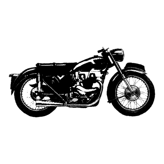
- Page 4 MATCHLESS "SUPER CLUBMAN" VERTICAL TWIN Model G9 Bore 66 m.m. Stroke 72·8 m.m. Capacity 498 c.c.
- Page 5 NTRODUCTION The modern motor cycle unquestionably provides one of the most healthy, economical and pleasant means of transport. In addition by reason of its superb braking, high power to weight ratio and ease of control it is, if used with due care one of the safest vehicles on the road. It is our sincere desire chat every owner should obtain from his mount the service, comfort and innumerable miles of low cost travel that we have earnestly endeavoured to build into it.
-
Page 6: Carburetter
DATA Identity Engine number … … … … … … … … On crankcase in front of left cylinder … … … … … … Frame number On seat lug of main frame, right side (below saddle) … … … …... -
Page 7: Sparking Plug
Lighting (bulbs) Part Location Type Voltage Wattage number … … Head lamp (Pre-focus) … Double filament 30 x 24 Single contact … … Pilot … … … … … … Double filament … … Rear lamp 18 and 3 Single contact 53205 Speedometer …... - Page 8 CONTROLS Throttle twist grip. On right handlebar. Twist inwards to open. When fully closed engine should just idle when hot. Air lever. Small lever on right handlebar. Pull inwards to increase air supply to carburetter. Once set, when engine has warmed up, requires no alteration for different road speeds.
- Page 9 (15) Petrol tank filler cap. Located in top of fuel tank. To release, slightly depress, turn fully to the left, and then lift away. There are two locking positions. The middle position, between the fully tightened down and " l i f t away" positions, is in the nature of a "...
- Page 10 illustration 1 Showing Controls...
- Page 11 DRIVING FUEL Although various quality fuels are again available, owners are advised to use only the best. The small economy that might be considered to accrue by using the cheaper grades is more than offset by the advantages obtained by using only Number One Grades.
-
Page 12: Contact Breaker
After the engine has started, slowly open the air lever until it runs evenly. Then set the throttle so that the engine is running at a moderate speed (neither racing nor ticking over) and allow to warm up. While doing this, check the oil circulation as detailed in page 12. -
Page 13: Rocker Adjustment
Special attention must be given, during the running in period, to such details as valve rocker adjustment, chains, brakes, contact breaker points, and steering head bearings, all of which tend to bed down in the first hundred miles or so. Particular note must be made of the adjustment of steering head bearings, which, if run in a slack condition, will be quickly ruined. - Page 14 CHECKING OIL CIRCULATION Provision is made to observe the oil in circulation and it is advisable to do this before each run. If the filler cap on the oil tank is removed the bent over end of the oil return pipe will be noticed some two inches below the level of the filler cap orifice and the returning oil can be seen running from it.
- Page 15 LUBRICATION LUBRICANTS TO USE Efficient lubrication is of vital importance and it is false economy to use cheap oils and greases. We recommend the following lubricants to use in machines of our make : FOR ENGINE LUBRICATION SUMMER WINTER (SAE-50) Mobiloil A Mobiloil D (SAE-30)
-
Page 16: Engine Lubrication
ENGINE LUBRICATION SYSTEM This is of the dry sump type. Two separate gear type oil pumps are used, one for delivery and the other for returning oil to the tank. Oil feeds by gravity to the delivery pump, by which it is forced, under pressure, to various parts of the engine, from whence i t drains back to the crankcase sump to be collected by the return pump and returned to the tank. - Page 17 ENGINE OIL CIRCULATION Oil, from the oil tank, is fed by gravity, through a coarse mesh metal filter, via an external pipe, to the suction side of the delivery pump, from whence it is discharged, under pressure, to a large and easily detachable felt filter that is housed in the crankcase. A pressure relief valve (see illustration 10) is incorporated purely as a safeguard when the oil is thick and cold, the blow off pressure of the valve being well above the normal oil pressure.
- Page 18 CLEANING OIL FILTERS To remove and clean the feed pipe metal filter : Drain Tank. Release the engine end of the oil feed pipe. (This leads from the rear outlet in the base of the oil tank to the forward banjo connection on the timing side of the crankcase.) Then remove the oil feed pipe by withdrawing the rubber connecting sleeve from the metal feed pipe protruding from the bottom of the oil tank.
- Page 19 To remove and clean the felt crankcase filter : Unscrew and remove the non return valve complete (016179) (See illustration 5). Withdraw the spring which removal of the non return valve will expose also withdraw the aluminium cap into which this spring is recessed. This will expose the felt fabric filter which can be withdrawn by inserting a finger in the open end.
- Page 20 To remove inspection cap :— Unscrew knurled screw about four turns. Slide cap sideways till the back plate can be slipped through the opening, and take away the complete cap assembly. When replacing inspection cap, centralise cork washer and then fully tighten knurled screw.
- Page 21 LUBRICATION CHART The figures in diamond frames refer to parts located on the left hand side of the machine and those in circles refer to parts located on the right hand side. Illustration 6 Lubrication Chart Engine Oil Locations Grease Locations MAIN OIL TANK.
- Page 22 MAINTENANCE PERIODICAL MAINTENANCE Regular maintenance attention to lubrication and certain adjustments must be made to ensure unfailing reliability and satisfactory service. This necessary attention is detailed below and owners are strongly recommended to carefully follow these suggestions and to make a regular practice of doing so from the first. The reference numbers, in brackets, refer to the locations specified on the Lubrication Chart, illustration 6.
- Page 23 EVERY 2,000 to 5,000 MILES (according to road conditions.) Air Filter (If fitted) clean and re-oil filter element. EVERY 3,000 MILES Rear chain In dry weather remove and soak in molten grease. (4). Brake pedal Inject small amount of grease. (5).
- Page 24 FREE SERVICE SCHEME FREE SERVICE SCHEME owners of N E W MODELS are entitled to one FREE SERVICE A N D INSPECTION at 500 miles, or, at latest, three months after taking delivery. This service is arranged by the supplying dealer to whom the Free Service Voucher must be handed.
- Page 25 ENGINE SERVICE TO ADJUST OVERHEAD ROCKERS (Tappet clearance) Using key bar 018055 remove screws securing a rocker cover. (It is desirable to deal only with one cover at a time). Lift off the cover, exposing the rocker. Using single ended spanner 015264, slightly slack off the nut of the bolt clamping the disc headed end of the rocker spindle.
- Page 26 ACCESS For all service w o r k to t h e upper part of the engine, other t h a n adjustment of t h e rockers, it is necessary, in order to obtain accessibility, to first remove the petrol tank.
- Page 27 TO REMOVE THE PETROL TANK Remove the twin seat. Close both petrol taps and remove the cap nut securing each petrol pipe banjo connector. Use two spanners, one to hold the tap and the other to unscrew the cap nut. Beware losing the fibre washers (4 in all) fitted one each side of each banjo connection.
- Page 28 TO REMOVE THE VALVES Remove rockers. Assuming that a valve spring compressor is not available : Prepare a block of Wood about 2" cube, lay same on a bench, place cylinder head over it so that the heads of both valves are supported on the block. Apply pressure to each valve spring cap, in turn, to Sufficiently compress the springs to permit the extraction of the split collet.
- Page 29 Illustration 9 Cross section of engine showing oil galleries, oil passages, and release valve.
- Page 30 REMOVING CYLINDER BARRELS AND PISTONS Unless it is desired to inspect the pistons and rings, during decarbonisation, they are, as already advised, best left undisturbed. Having removed the cylinder heads w i t h d r a w the cylinder barrels by : Lift away the four push rods, identify them for re-fitting and lay aside.
- Page 31 TO RE-FIT THE CYLINDER HEADS Clean the valve stems and the bores of the valve guides with rag moistened with petrol, make sure all other parts are clean, then smear each valve stem with clean engine oil and proceed to re-fit the valve stems by reversing the procedure taken to dismantle them. Insert the four valve push rods Into their original positions and, after making sure that the cylinder head gaskets are undamaged and in position, proceed to fit the two heads and leave the two sets of four cylinder head retaining nuts finger tight.
- Page 32 NOTE—Under excessive oil pressure the relief valve plunger (11) is forced outward against the influence of spring (12) to an extent sufficient to uncover the drilled cross hole in plunger through which part of the oil delivery escapes into the timing case.
- Page 33 MAIN OIL FEED FROM TRANSMISSION SIDE CRANKCASE TO CRANKSHAFT Illustration 11 Showing mounting for centre bearing for crankshaft, and a connecting rod with big-end bearing TO RE-TIME THE IGNITION Before proceeding to time the ignition it is advisable first to check the contact breaker point gap, which should be from .010"...
- Page 34 Place the ignition control lever in the fully advanced position. Next, taking care not to disturb the piston position, turn the magneto in a clockwise direction (looking at the contact breaker end of the magneto) until the contact breaker points are just about to separate by reason of the fibre block on the bell crank lever commencing to mount the lower cam hump.
- Page 35 Illustration 12 Carburetter details in assembly order.
- Page 36 CARBURETTER SERVICE The information given in this section includes all that will normally be required by The average rider. For further details, particularly those connected with racing and the use of special fuels, we refer the enquirer to the manufacturers of the carburetter, Amal Ltd., Holford Road, W i t t o n , Birmingham, 6.
- Page 37 TWIST GRIP ADJUSTMENT A screw is provided in one of the halves of the twist grip body to regulate the spring tension on the grip rotating sleeve. This screw, which is locked by a nut, must be screwed into the body to increase the tension. The most desirable state of adjustment is that when the grip is quite free and easy to operate but, at the same time, will stay in the position in which it is placed.
- Page 38 CARBURETTER T UNI N G INFORMATION Poor idling may be due to : Air leaks. Either at junction of carburetter and inlet manifold, or by reason of badly worn inlet valve stems or guides. Faulty engine valve seatings. Sparking plug faulty, or its points set too closely. Ignition advanced too much.
- Page 39 TRANSMISSION SERVICE THE GEAR BOX The gear box provides four speeds and has a positive foot change, operated by the right foot and a kick-starter. It is retained to the frame by being clamped between the two engine rear plates by two bolts.
- Page 40 Remove the nut and small spiral spring securing small gear indicator disc from the cam barrel spindle. Next remove the five cheese head screws by which the K.S. case cover is secured to the gear box end plate. Withdraw the cover about ½ inch, holding the K.S. pedal firmly while doing so. Now swing the K.S.
- Page 41 TO REMOVE FRONT CHAINCASE AND CLUTCH ASSEMBLY To remove outer half of f r o n t chaincase Remove left side exhaust pipe and silencer (the pipe with its silencer is taken away as a unit). Remove the left side footrest arm. Place tray under chaincase to catch oil.
- Page 42 Fit engine shock absorber by : Ensure the spacing collar, which fits between crankcase roller bearing and the back of the engine sprocket, is in position on the driving side flywheel axle. Then place in position, on the flywheel axle, in the order specified, the engine sprocket, the shock absorber cam, the spring and cap washer and, finally, the shock absorber retaining bolt.
- Page 43 Whilst slowly tightening this binding screw apply at the same time light taps all round the band exterior using a small rubber mallet. These light taps will cause the metal band to creep on the rubber to ensure an even all-round pressure.
- Page 44 Before replacing the domed clutch cover, test for slip by starting up the engine, engaging top gear, and applying the rear brake when it should be possible to pull up the engine on full throttle without slip occurring. If to cure slip it is found necessary to further tighten the adjusting nuts this is a clear indication that either the clutch springs have lost their tension, the inserts are so worn that they require renewal or that they have become impregnated with oil.
- Page 45 To remove a clutch control cable Remove the oil filler cap from the kick-starter case cover. Screw right home the clutch cable adjuster that is located in the top of the kick-starter case cover. Disengage, from the operating lever, the clutch cable inner wire by operating through the oil filler cap opening.
- Page 46 REMOVING A N D REFITTING REAR C H A I N To protect the rear chain from mud and water it is very closely shrouded by the chain guard and removing the chain without first detaching the chain guard can present con- siderable difficulty.
- Page 47 FORK & FRAME SERVICE STEERING HEAD ADJUSTMENT The steering head frame races are of the floating self-aligning type and have spherical seats. Therefore they do not fit tightly in the head lug. Occasionally test the steering head for correct adjustment by exerting pressure upwards from the extreme ends of the handlebars.
- Page 48 Illustration 15 Introduced in early 1941 for use under strenuous war conditions by all t h e allied armies, it remains unaltered, except in detail, to this day, and copied practically universally. hydraulic dampers operate in tubular members located inside the main tubes. As w i l l be seen t h e aluminium sliding members operate upon steel bushes attached to the b o t t o m ends of the main tubes and also upon bakelite bushes, secured to t h e t o p end of the...
- Page 49 has no othe r source of escape bu t past this sleeve and the adjacent small metered bleed hole. This intentionally restricted passage causes a considerable damper effect to the recoil action. It w i l l thus be gathered that on the shock movement of the f o r k , slight damper action occurs, w i t h a greatly increased damper action on the reverse movement, both actions automatically increasing in effect the more violent the movement.
- Page 50 Remove the handlebar half clip and lay the handlebars, complete with controls, upon a pad on top of the petrol tank. Detach the front brake cable from the forks. (First remove the slotted yoke end and then completely unscrew the cable adjuster.) Remove the snap on dome caps and unscrew the hexagon plug on top of each inner tube, raise same and slacken the lock nuts securing the damper rods attached.
- Page 51 Illustration 16...
- Page 52 REF. DESCRIPTION WASHER. LEATHER, FOR FORK SPRING TOP SEATING. BUFFER, RUBBER. FOR FORK INNER TUBE. SPRING, MAIN, FOR FRONT FORK. BUFFER, RUBBER, FOR FORK INNER. TUBE. BUFFER, RUBBER, FOR FORK INNER TUBE. WASHER, LEATHER, FOR FORK SPRING BOTTOM SEATING. EXTENSION, FOR FORK SLIDER. OIL SEAL.
- Page 53 REAR SUSPENSION The rear wheel is mounted in a fork that is hinged just behind the gear box. The hinge has robust plain bearings lubricated from a reservoir of 1½ fluid ounces (42.6 c.c.) of heavy gear oil which is sufficient to last almost indefinitely. Provision is, however, made for replenishment should same be required.
- Page 54 Illustration 18 Showing " Ghost " view of " TELEDRAULI C " leg...
- Page 55 To check oil content of " TELEDRAULIC " leg and top-up : Dealing with one leg at a time, remove top securing bolt, taking care to observe the location of the spacing washers on it. Remove bottom securing bolt and take away the leg.
- Page 56 TO REMOVE THE REAR CHAIN GUARD Remove the rear wheel. (See Wheel Section). Remove the bolt retaining the front end of the chain guard to the rear fork. Remove the bolt retaining the rear end of the chain guard to the rear fork. (There is one spacer on this bolt, between the two sides of guard.) ALWAYS QUOTE...
- Page 57 WHEELS AND BRAKES TO REMOVE FRONT WHEEL Place machine on both stands. Remove the split pin, and pin, retaining yoke end of front brake cable to the brake expander lever. Remove bolt retaining brake anchor stay to brake cover plate. Slacken the nut on the left-hand end of front wheel spindle.
- Page 58 Illustration 19 1 REAR BRAKE COVER PLATE. 2 BOLT, ANCHORING COVER PLATE TO REAR FRAME. WHEEL BEARINGS A N D ADJUSTMENT The wheel bearings are of taper roller type. See illustrations. The outer cups for the rollers are pressed into the hub shell. They have a fixed location one side and an adjustable location on the other.
- Page 59 A service method of ensuring correct adjustment is: Slacken the lock nut. Tighten the adjusting ring until all slackness has been taken up. Slacken back the adjusting ring exactly one-half turn. Tighten the lock nut, making sure that, when doing so, the adjusting ring does not creep round, and the cover disc positioned to permit grease gun application to the nipple.
- Page 60 Front and rear hubs Illustration 20 CIRCLIP. WASHER RETAINING SEAL. ADJUSTING RING LOCKNUT. OIL SEAL CUP OIL SEAL NUT LOCATING BRAKE COVER PLATE. OIL SEAL NUT SECURING BRAKE COVER PLATE. OIL SEAL CUP. SPINDLE END WASHER. WASHER RETAINING SEAL. ADJUSTING RING. SPINDLE END NUT.
- Page 61 TO DISMANTLE REAR WHEEL BEARINGS With wheel still in situ first of all slacken the nut (16) securing the speedometer drive gear box. Then remove the wheel from cycle when the above nut should be removed and the speedometer gear box withdrawn. Next, slacken the adjuster sleeve lock nut (13) and completely unscrew the adjuster sleeve (14) which will come away together with the sleeve upon which speedometer drive is mounted and also the cover disc.
- Page 62 Rear brake and wheel bearings Illustration 22 SPACER FOR WITHDRAWABLE SPINDLE. WITHDRAWABLE WHEEL SPINDLE OUTER SPACER BRAKE COVER SPEEDOMETER GEAR BOX SLEEVE. PLATE. RING RETAINING OIL SEAL (Small). WASHER FOR COVER PLATE FIXING NUT. OIL SEAL. BRAKE COVER PLATE FIXING NUT. CUP FOR OIL SEAL.
-
Page 63: Brake Shoe Adjustment
BRAKE DRUMS The front wheel brake drum is a shrunk in fit in the hub shell (assembled under heat) and secured additionally by five screws. The rear brake drum is mounted on a separate ball bearing and the drive to rear wheel is by means of five studs projecting from the hub face which engage with holes in the drum back face, thereby permitting removal of the rear wheel with the brake drum still in situ. - Page 64 Centralise brake shoes by: Ensure the nut securing the cover plate to the wheel spindle and also the fulcrum stud nut (front only) are slightly slacked off. Place on the brake expander lever a tubular spanner (to increase the leverage), and, while maintaining pressure on the tubular spanner (to expand fully the brake shoes), fully tighten the spindle nut binding the cover plate to the spindle and also the nut on fulcrum stud.
- Page 65 REAR BRAKE ADJUSTMENT Major adjustment of the rear brake shoes is made on the brake thrust pins, by fitting packing washers under the pins, as already described. Minor adjustment of the rear brake shoes is made by altering the position, on the brake rod, of the knurled adjusting nut.
- Page 66 TYRES AND SERVICE Obtaining satisfactory life and service from the tyres is largely a matter within the user's control because the first essential is correct inflation. Check tyre pressures with a low pressure gauge at least once a week. Inflate as may be necessary. Avoid unnecessary, or "...
- Page 67 TYRE FITTING Re-fit inner tube and outer cover by: Place one edge of cover right into well of rim, with the three white dots on the cover side adjacent to the valve hole, and, commencing diametrically opposite, and using the hands only, work the cover over the edge of the rim.
- Page 68 USEFUL INFORMATION In the following five paragraphs are particulars of failures and troubles that can occur, together with the probable reasons. These troubles are arranged in the order of their probability, TRACING TROUBLES Engine fails to start, or is difficult to start, may be due to : Water on high-tension pick-ups.
- Page 69 Engine overheats may be due to : Lack of proper lubrication. (Quality or quantity of oil). Faulty sparking plugs. Air control to carburetter out of order. Punctured carburetter float. Engine carbonised. Weak valve springs. Pitted valve seats. Worn piston rings. Ignition setting incorrect.
- Page 70 CLEANING THE MACHINE Do not attempt to rub, or brush, mud off the enamelled surfaces because this will soon destroy the sheen of the enamel. Mud, and other road dirt, should be soaked off with water. The best method is to use a small hose, taking care not to direct water on to the engine, carburetter, magneto and other such parts.
- Page 71 ELECTRICAL SERVICE ELECTRICAL EQUIPMENT LUCAS electrical equipment is fitted and this comprises three independent electrical circuits, as follows : (1) IGNITION—Magneto, High-tension wires, Sparking plugs and Cut-out switch. (2) CHARGING—Dynamo Automatic Voltage Control Unit and Battery. (3) LIGHTING A N D ACCESSORIES—Lamps, Horn, Switches and wiring. CONTACT-BREAKER LOCATING SPRING SPRING...
- Page 72 Illustration 27 Showing dismantled components of magneto Adjustment every 3,000 miles Remove the contact breaker cover 3nd turn the engine until the contact points are fully opened. Check the gap with a gauge having a thickness of .012" (Spanner 015023 has a gauge of this thickness as an integral part of it).
- Page 73 If it is dirty, clean with a cloth moistened with petrol, If the brush is worn to within 8" of the shoulder it must be renewed. Treat both pick-ups and their brushes. While the pick-ups are removed, clean the slip ring track and flanges by holding a soft cloth on the ring by means of a suitably shaped piece of wood, while the engine is slowly turned.
- Page 74 Magneto removal and fitting The magneto is " spigot fitting " and is retained to the crankcase by two studs and one bolt. To remove the magneto it is necessary to : Take away the timing gear cover. Withdraw the driving gear from the magneto shaft. (Already described in the Engine Section).
- Page 75 Test Dynamo in position by : (a) Remove the two wires from the dynamo terminals and connect the two terminals with a short length of wire. (b) Start the engine and set to run at normal idling speed. (c) Connect the negative lead of a moving coil voltmeter (calibrated not less than 0 to 10 volts) to either of the two dynamo terminals and connect the positive lead to a good earth point on the dynamo or engine.
-
Page 76: Cut-Out Unit
The A.V.C. Unit is retained by two bolts with self-locking nuts. The self-locking nature of the nuts prevents subsequent slacking off. The four terminals of the A.V.C. Unit are plainly marked by the letters F.A.D.E. Wires from F and D go to similarly marked terminals on the dynamo. - Page 77 The specific gravity of the electrolyte indicates the CORRECT-ACID-LEVEL DEVICE state of charge of the battery. W i t h a fully charged battery the specific gravity of the electrolyte should be 1·280 to 1·300. Check the gravity by means of a hydrometer, and if it is below 1·150 the battery should be charged as soon as possible by the normal running of the motor cycle.
- Page 78 LIGHTING A N D ACCESSORIES Headlamp A LUCAS headlamp is fitted and snugly mounted, on each side is a neat torpedo shaped pilot lamp. These pilot lamps and also the head lamp are secured to the front fork arms by means of tubular bolts through which a wire passes to each pilot lamp. The head- lamp bulb has two filaments one of which provides the main driving beam and the other a dipped beam brought into operation as required by the dipping switch on the left handlebar.
- Page 79 To replace headlamp rim and light unit Lay the light unit in the rim so that the location block on the unit back engages with the forked bracket on the rim. Replace, by springing in, the spring clips so that they are evenly spaced around the rim.
- Page 80 Terminals All models have the POSITIVE battery terminal connected to "EARTH ". The earth wires (two—one from regulator, the other from terminal of "battery) and the high-tension wires (two—one on sparking plug end of each wire from magneto to sparking plug) have terminals of the solid sleeve type having an eye at the extreme end. To make such a connection, it is necessary to bare the end of the wire for a", pass the terminal over the wire so that the bared end fully enters the reduced core of the terminal and then flatten that part by either pinching in a vice or by hammering.
- Page 81 SIDELAMP SIDELAMP LIGHTING SWITCH SPEEDOMETER DIPPER SWITCH LIGHT HORN PUSH DYNAMO MAGNETO REGULATOR BATTERY (Positive earth) HORN SNAP CONNECTOR TAIL LAMP W 97832 Illustration 32 Wiring diagram...
- Page 82 REPAIRS SERVICE A N D REPAIRS The instructions regarding repairs should be clear and definite, otherwise the cost may be greater than that expected. We shall be pleased to give estimates for repairs if parts are sent to us for that purpose. If the estimate is accepted, no charge is made for the preliminary examination, but, should it be decided not to have the work carried out, it M A Y be necessary to make a charge to cover the cost of whatever dismantling and re-assembly may have been done to prepare the estimate.
- Page 83 SERVICE The Service and Repair Department is situated in Burrage Grove, Plumstead, London, S.E.18, and is open on Mondays to Fridays from 8.30 a.m. to 12.55 p.m.—2.0 p.m. to 5.30 p.m. It is closed on Saturdays, Sundays and National Holidays. It exists for the purposes of : (a) Giving technical assistance verbally or through the post.
- Page 84 THE MACHINE AND THE LAW Every motor cycle used on the public roads must be registered and carry the registration numbers and licence disc allotted to it. The dealer, from whom the machine is bought, will, generally, attend to all matters legally essential before it is used on the public roads. To register a new machine Send to the Local Registration Authority the following : (a) Form "...
- Page 85 TOOLS AND SPECIAL EQUIPMENT TOOLS The standard tool kit, issued with each new machine, contains : 017253 Tool bag. Tyre inflator. 017114 017007 Tyre lever. 017248 Pliers. 011188 Gudgeon pin circlip pliers. Screwdriver, 017256 017246 Grease gun. Adjustable wrench. 017249 017252 Sparking plug box spanner and tommy bar.
- Page 86 BADGES Neat monogram badges are now available at a cost of 1/6, plus 6d. postage. They can be supplied as a tie pin, as a brooch or for fitting in a button hole. When ordering state type required. Illustration 33 Tool Kit...
- Page 87 GUARANTEE We give the following guarantee with our motorcycles, rnotorcycle combinations and sidecars, which is given in place of any implied conditions, warranties or liabilities whatsoever, statutory or otherwise, all such implied conditions, warranties and liabilities being in all cases excluded. statement, description, condition or representation contained in any catalogue, advertisement, leaflet or other publication shall not be construed as enlarging, varying or overriding this guarantee.
-
Page 88: Table Of Contents
ILLUSTRATIONS Illustrations Page Battery … … … … … … … … … Brake adjustment, front … … … … … … … Brake adjustment, rear … … … … … … … Brake shoe adjustment … … … … …... - Page 89 INDEX Page Carburetter Service … … … … … … … … Controls … … … … … … … … … … Data … … … … … … … … … … … Driving … … … … …...
- Page 90 GENUINE MATCHLESS SPARES PURCHASED FROM AN AUTHORISED "MATCHLESS" DEALER OR FROM THE FACTORY, ARE IDENTICAL WITH PARTS ORIGINALLY BUILT INTO YOUR MOTOR CYCLE. BY USING GENUINE SPARES YOU ARE ASSURED THEY WILL FIT ACCURATELY AND GIVE SATISFACTORY SERVICE...
Need help?
Do you have a question about the Super Clubman G9 1955 and is the answer not in the manual?
Questions and answers