Sign In
Upload
Download
Table of Contents
Contents
Add to my manuals
Delete from my manuals
Share
URL of this page:
HTML Link:
Bookmark this page
Add
Manual will be automatically added to "My Manuals"
Print this page
×
Bookmark added
×
Added to my manuals
Manuals
Brands
Matchless Manuals
Motorcycle
1949 CLUBMAN G3L
Maintenance manual
Matchless G3L Maintenance Manual
Hide thumbs
Also See for G3L
:
Maintenance manual and instruction book
(96 pages)
1
2
3
4
5
6
7
8
9
10
11
12
13
14
15
16
17
18
19
20
21
22
23
24
25
26
27
28
29
30
31
32
33
34
35
36
37
38
39
40
41
42
43
44
45
46
47
48
49
50
51
52
53
54
55
56
57
58
59
60
61
62
63
64
65
66
67
68
69
70
71
72
73
74
75
76
77
78
79
80
81
82
83
84
85
86
87
88
89
90
91
92
93
94
Table Of Contents
95
page
of
95
Go
/
95
Contents
Table of Contents
Bookmarks
Table of Contents
G3L and G80 Rigid Frame
G3LS and G80S Spring Frame
Safety on the Road
Data
Capacities
Carburetter (Touring and Rigid Frame Competition Models Only)
Compression Ratios
Gear Box
Oil Tank
Ignition (Magneto)
Gear Ratios, Competition Rigid Frame Models
Gear Box Ratios
Gear Ratios, Touring (Rigid and Spring Frame) and Spring Frame Competition
Oversize Parts
Pistons (Standard Size)
Piston Rings
Weight
Sparking Plug
Controls
Showing Controls
Fuel Supply
Starting the Engine from Cold
Driving
Fuel
Stopping the Engine
On the Road
Stopping the Machine
Running in
Notes on Driving
Checking Oil Circulation
Lubrication
Lubricants to Use
For Engine Lubrication
For Gear Box Lubrication
Engine Oil Circulation
Engine Lubrication System
Engine Oil Pump
The Oil Tank and Filters
To Remove the Felt Oil Filter
Adjustment of Oil Feed
Exhaust Valve Stem Lubrication
Lubrication Points to Remember
Gear Box Lubrication
Hub Lubrication
Brake Drum Bearing (Spring Frame Models Only)
Chain Lubrication
Stand Fixing Bolt Lubrication
Speedometer Lubrication
Brake Pedal Lubrication
Brake Rod Joint Lubrication
Lubrication Chart
Periodical Maintenance
Daily
Weekly
Every 1,000 Miles
Every 3,000 Miles
Every 5,000 Miles
Every 10,000 Miles
Engine Service
Access
To Replace the Rocker Box
To Replace the Petrol Tank
To Remove the Petrol Tank
To Remove the Rocker Box
Valve Spring Compressor
Removing Carbon Deposit
Valve Grinding
Showing Flywheel in Exploded Form
To Replace the Cylinder Head
TO REMOVE the CYLINDER BARREL and Plston
To Replace the Piston and Cylinder Barrel
Cam Contour
Camshaft Timing Marks
Valve Timing
Inlet Valve Timing
Exhaust Valve Timing
Tappet Adjustment
To Re-Time the Ignition
Check Contact Breaker Points
Set Ignition Firing Point
Replace Rod in Sparking Plug Hole
Oil Pump
To Remove and Replace the Oil Pump Plunger
Oversize Parts and Re-Boring Cylinder Barrel
Removing Sparking Plug
Carburetter Details in Assembly Order
Carburetter Function
Carburetter Adjustment
Twist Grip Adjustment
Air Filter
Carburetter Tuning Information
To Remove Gear Box End Plate for Examination of Gears
To Re-Assemble
To Remove Front Chaincase and Clutch Assembly
To Remove Front Driving Chain and Clutch Assembly Complete
To Remove Dynamo Chain and Back Half of Chaincase
To Re-Fit the Front Chaincase and Clutch
Fit the Clutch Centre and Sprocket
Fit Outer Half of Front Chaincase
Fit the Front Chain and Lock the Clutch Centre Nut
Fit the Clutch Plates and Springs
Clutch Spring Adjustment
Showing Clutch, Gear Box Main Shaft and Clutch Operating Mechanism
Clutch Operating Mechanism Adjustment
To Remove a Clutch Control Cable
To Replace a Clutch Control Cable
Front Chain Adjustment
Tighten the Front Chain
Rear Chain Adjustment
Tighten Dynamo Chain
Removing and Refitting Rear Chain
Dynamo Chain Adjustment
Notes on Rear Chain Adjustment
Magneto Chain Adjustment
Engine Shock Absorber
Steering Head Adjustment
Front Forks (Teledraulic)
Adjust Steering Head Bearings
Front Fork " Topping up "
To Remove the Complete Front Fork Assembly
To Remove a Fork Inner Tube Assembly
To Re-Fit a Complete Front Fork Assembly
To Remove a Fork Slider (Either Side)
Description
Rear Suspension
Showing " Ghost " View of " TELEDRAULIC " Leg
Prop Stand
Centre Stand
Front Stand
REAR STAND (Rigid Frame Models)
To Remove Oil Tank and Battery Carrier
To Remove the Rear Chain Guard
To Remove Detachable Rear Wheel
To Remove Front Wheel
To Re-Fit Front Wheel
Wheels and Brakes
To Remove Rear Wheel
To Re-Fit Rear Wheel
Wheel Bearings and Adjustment
To Dismantle Front Wheel Bearings
Showing Front Hub and Brake also Rear Hub
Showing Rear Wheel Bearings and Brake Drum
To Dismantle Rear Wheel Bearings
Front Brake Cover Plate
Brake Drums
Brake Shoe Adjustment
Front Brake Adjustment
Rear Brake Adjustment
Brake Pedal Adjustment
Rims and Spokes
Tyres and Service
Tyre Removal
Tyre Fitting
Tyre Pressures
Engine Misses Fire May be Due to
Engine Fails to Start, or Is Difficult to Start, May be Due to
Tracing Troubles
Useful Information
Excessive Oil Consumption
Excessive Petrol Consumption
Steering Unsatisfactory
Engine Overheats May be Due to
Abnormal Tyre Wear
Cleaning the Machine
Chromium Plating
Ignition
Adjustment of Contact Breaker (Magneto Type SR-1)
Sparking Plug
Charging
To Remove the Dynamo
Lighting and Accessories
Headlamp
To Remove Headlamp Rim and Light Unit
To Replace the Headlamp Rim and Light Unit
Horn
Fuses
Snap Wire Connector
Terminals
Wiring Diagram
Proprietary Fittings
Correspondence and Orders
Repairs
The Driver and the Law
The Machine and the Law
To Register a New Machine
Ignition Suppressors
Lamps
Tools and Special Equipment
Badges
Index
Table of Contents
Illustrations
Advertisement
Quick Links
1
G3Ls and G80S Spring Frame
2
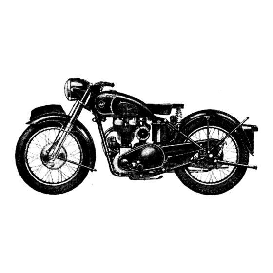
G3L and G80 Rigid Frame
Download this manual
MAINTENANCE
MANUAL
INSTRUCTION
BOOK
350 c.c. and 500 c.c.
MATCHLESS
SPRING FRAME AND RIGID
SINGLE CYLINDER MODELS
PRICE 2/6 NETT
MATCHLESS
M O T O R
PROPRIETORS : ASSOCIATED MOTOR CYCLES LIMITED
PLUMSTEAD • LONDON • S.E.18
AND
for
1955
C Y C L E S
Table of
Contents
Previous
Page
Next
Page
1
2
3
4
5
Advertisement
Table of Contents
Need help?
Do you have a question about the G3L and is the answer not in the manual?
Ask a question
Questions and answers
Related Manuals for Matchless G3L
Motorcycle Matchless 1949 CLUBMAN G3L Maintenance Manual And Instruction Book
(96 pages)
Motorcycle Matchless G11 Workshop Manual
1957 500 c.c 600 c.c. twin cylinder models ajs model 20 ajs model 30 (71 pages)
Motorcycle Matchless G9 Workshop Manual
1957 500 c.c 600 c.c. twin cylinder models ajs model 20 ajs model 30 (71 pages)
Motorcycle Matchless G80 Maintenance Manual
(95 pages)
Motorcycle Matchless G80S Maintenance Manual
(95 pages)
Motorcycle Matchless G80C Maintenance Manual
(95 pages)
Motorcycle Matchless G80CS Maintenance Manual
(95 pages)
Motorcycle Matchless G2CS Instruction Book
(60 pages)
Motorcycle Matchless G5 Instruction Book
(60 pages)
Motorcycle Matchless Super Clubman G9 1955 Instruction Book
(92 pages)
Motorcycle Matchless 46/G3L 1946 Maintenance Manual And Instruction Book
(92 pages)
Motorcycle Matchless 1964 G3 350 Instruction Book
(104 pages)
Motorcycle Matchless 1964 G12CSR 650 Instruction Book
(104 pages)
This manual is also suitable for:
G3ls
G3lcs
G80
G80s
G80c
G80cs
...
Show all
G3lc
Table of Contents
Save PDF
Print
Rename the bookmark
Delete bookmark?
Delete from my manuals?
Login
Sign In
OR
Sign in with Facebook
Sign in with Google
Upload manual
Upload from disk
Upload from URL


Need help?
Do you have a question about the G3L and is the answer not in the manual?
Questions and answers