
Related Manuals for Datacolor AutoLab TF Series


Summary of Contents for Datacolor AutoLab TF Series
- Page 1 AutoLab TF Laboratory Dispenser Technical Manual Part number: TF-0022-0924 Revision 5.0 May 2006...
- Page 2 Datacolor. Whilst every effort has been made to ensure the accuracy of this manual, Datacolor can accept no responsibility for any omissions or errors it may contain. Datacolor reserves the right to make improvements and/or changes in the product(s) features and specifications described in this manual at any time.
-
Page 3: Table Of Contents
Index DOCUMENT VERSION UPDATES ......................5 ABOUT THIS MANUAL.......................... 6 ........................6 OW TO USE THIS MANUAL CHAPTER1: GETTING TO KNOW YOUR AUTOLAB TF..............7 1-1 P ........................... 7 RINCIPLE HART 1-2 G TF ....................8 ETTING 1-2-1 Standard Specification ....................... 8 1-2-2 Picture of AutoLab TF with no conveyor (TF-40/80/120/160).......... - Page 4 2-5 S ..........................97 ERVO YSTEM 2-5-1 Sanyo PV Type Amplifier Servo System.................97 2-5-2 Sanyo Denki PV Type Servo Amplifier................99 2-5-3 Error Message Table For PV Type Servo Amplifier .............103 2-5-3 Meaning of parameters in PV type amplifier ..............108 2-5-4 Sanyo Denki Q type amplifier ..................113 2-6 C PC ........................145 ONNECT...
-
Page 5: Document Version Updates
AutoLab TF Dispenser Technical Manual – Revision 5 Document version updates Revision 2 has the following updates made compared to revision 1, released: Addition of information on new model of dispenser, AutoLab TF-88 Amended dimensions for all models Improved photos now included Reference to water pressure regulator now included with each system Reference to improved electronic cabinet with mechanical circuit breaker, instead of electrical Reference to newer design LA50B (600+N2) CPU... -
Page 6: About This Manual
AutoLab TF Dispenser Technical Manual – Revision 5 About this manual How to use this manual This manual focuses on the hardware description and maintenance of the AutoLab TF-40, 80, 88, 120, 160 and 168 dispense. It Includes construction of system, introduction of all PLC modules, maintenance procedure, troubleshooting guide etc. - Page 7 Addendum: Important safety note before operating or using the Datacolor Autolab Dispensing System: It is strongly recommended that all personnel refrain from carrying smartphones, smart devices, or magnetic items in close proximity to the Autolab Dispensing System. In rare instances, we have observed that these devices may cause interference, potentially compromising the dispenser's intended operation and posing a safety risk.
-
Page 8: Chapter1: Getting To Know Your Autolab Tf
AutoLab TF Dispenser Technical Manual – Revision 5 CHAPTER1: GETTING TO KNOW YOUR AutoLab TF 1-1 Principle Chart LA50B SERVO SERVO SERVO MOTOR Amplifier module (Z AXIS) MONITOR LA50B module INJECTOR RS485 232 to 485 Adapter COMPUTER RS232C BEAKER RS232C PRINTER SCALE AutoLab TF dispensers Technical Manual... -
Page 9: Getting To Know Autolab Tf
AutoLab TF Dispenser Technical Manual – Revision 5 1-2 Getting To Know AutoLab TF 1-2-1 Standard Specification AutoLab TF TF 40 TF 80 TF 120 TF 160 TF 88 TF 128 TF 168 Total bottles Number of dye bottles Number of water tank NONE Number of aux. -
Page 10: Picture Of Autolab Tf With No Conveyor (Tf-40/80/120/160)
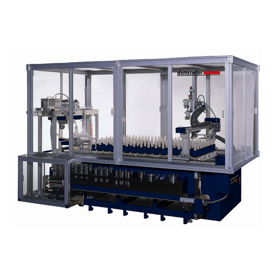
AutoLab TF Dispenser Technical Manual – Revision 5 1-2-2 Picture of AutoLab TF with no conveyor (TF-40/80/120/160) 1-2-3 Picture of AutoLab TF with conveyor (TF-88/128/168) AutoLab TF dispensers Technical Manual TFTMTF / Rev 5.0 / 24 May 2006 Page 9 of 150... -
Page 11: Line Drawings Of Autolab Tf Models
AutoLab TF Dispenser Technical Manual – Revision 5 1-2-4 Line drawings of AutoLab TF models Line drawing of AutoLab TF-40 Line drawing of AutoLab TF-80 AutoLab TF dispensers Technical Manual TFTMTF / Rev 5.0 / 24 May 2006 Page 10 of 150... - Page 12 AutoLab TF Dispenser Technical Manual – Revision 5 Line drawing of AutoLab TF-88 Line drawing of AutoLab TF-120 Line drawing of AutoLab TF-128 AutoLab TF dispensers Technical Manual TFTMTF / Rev 5.0 / 24 May 2006 Page 11 of 150...
- Page 13 AutoLab TF Dispenser Technical Manual – Revision 5 Line drawing of AutoLab TF-160 Line drawing of AutoLab TF-168 AutoLab TF dispensers Technical Manual TFTMTF / Rev 5.0 / 24 May 2006 Page 12 of 150...
-
Page 14: Description Of Stock Solution Platform
AutoLab TF Dispenser Technical Manual – Revision 5 1-3 Stock Solution Platform 1-3-1 Description of Stock Solution Platform Solution Bottle For stock of dye solution and its capacity is 1000 ml. Bottle cap The blue barrel-drain lid is used to prevent the solution splash out and fasten injectors. There is a scraper inside. -
Page 15: Picture Of Stock Solution Platform
AutoLab TF Dispenser Technical Manual – Revision 5 1-3-2 Picture of Stock Solution Platform Stock solution platform Injector AutoLab TF dispensers Technical Manual TFTMTF / Rev 5.0 / 24 May 2006 Page 14 of 150... -
Page 16: Agitation Module
AutoLab TF Dispenser Technical Manual – Revision 5 1-4 Agitation Module 1-4-1 Description of Agitation Module Motor This motor agitates agitator by a belt. Agitator This device set under each dye solution bottle and auxiliary bottle. The agitator is agitated the stirrer by magnetic force. Stirrer Every dye solution bottle and auxiliary bottle has a stirrer. -
Page 17: Control Flowchart Of Agitation
AutoLab TF Dispenser Technical Manual – Revision 5 1-4-2 Control flowchart of Agitation LA50B CPU module LA50B D.I.O module OUTPUT Relay Board Agitation Controller Motor AutoLab TF dispensers Technical Manual TFTMTF / Rev 5.0 / 24 May 2006 Page 16 of 150... - Page 18 AutoLab TF Dispenser Technical Manual – Revision 5 1-4-3 The Pictures of Agitation AutoLab TF dispensers Technical Manual TFTMTF / Rev 5.0 / 24 May 2006 Page 17 of 150...
-
Page 19: X-Y-Zmechanism
AutoLab TF Dispenser Technical Manual – Revision 5 1-5 X-Y-Z mechanism X-Y-Z mechanism 1-5-1 Description of Dispensing Servo motor of X axis This motor moves the robot forward and backward. Servo motor of Y axis This motor moves the robot leftward and rightward. Servo motor of Z axis This motor controls the volume of injector. -
Page 20: Pictures Of X-Y-Z Mechanism
AutoLab TF Dispenser Technical Manual – Revision 5 1-5-2 Pictures of X-Y-Z mechanism X axis homing sensor Y axis homing sensor AutoLab TF dispensers Technical Manual TFTMTF / Rev 5.0 / 24 May 2006 Page 19 of 150... - Page 21 AutoLab TF Dispenser Technical Manual – Revision 5 AutoLab TF dispensers Technical Manual TFTMTF / Rev 5.0 / 24 May 2006 Page 20 of 150...
-
Page 22: Dispense Area
AutoLab TF Dispenser Technical Manual – Revision 5 1-6 Dispense Area 1-6-1 AutoLab TF 40/80/120/160 System 1-6-1-1 Water Dispensing Water tank This water tank with level sensor and automatic refill, and the capacity is 7 litres. Over flow tube For overflow, in case of refill control errors, water will be able to flow away from the tube. Drain cock valve For open the drain manually. - Page 23 AutoLab TF Dispenser Technical Manual – Revision 5 AutoLab TF dispensers Technical Manual TFTMTF / Rev 5.0 / 24 May 2006 Page 22 of 150...
- Page 24 AutoLab TF Dispenser Technical Manual – Revision 5 1-6-1-2 Dyepot tray movement Ack button Push the button moving dye pot to and out the scale position. Air regulator For set the air pressure. The pressure should be within the range of 4.5~ 6.0 kg/cm Air valves of water dispensing head The 5-3 solenoid valve is used to control the front, middle and back dispense head.
- Page 25 AutoLab TF Dispenser Technical Manual – Revision 5 1-6-1-3 Pictures of Electronic Cabinet for Water Dispense Water pressure regulator Solenoid set for air cylinder Main air pressure regulator Main air inlet Main water inlet Water pressure regulator AutoLab TF dispensers Technical Manual TFTMTF / Rev 5.0 / 24 May 2006 Page 24 of 150...
- Page 26 AutoLab TF Dispenser Technical Manual – Revision 5 AutoLab TF dispensers Technical Manual TFTMTF / Rev 5.0 / 24 May 2006 Page 25 of 150...
-
Page 27: Autolab Tf 88/128/168 System
AutoLab TF Dispenser Technical Manual – Revision 5 1-6-2 AutoLab TF 88/128/168 System 1-6-2-1 Auxiliary/Water Dispensing Auxiliary bottle There are 7 bottles of auxiliary solution, and each one is 1000 ml. Agitate device Containing agitation mechanism for all auxiliary bottles, the power on/off and speed is controlled by manual. - Page 28 AutoLab TF Dispenser Technical Manual – Revision 5 Tray push out cylinder control valve This device is used to control the cylinder that move the outlet tray push bar to front and back position. Terminal connecter This device is used to connect electronic control cable and auxiliary cabinet control cable.
- Page 29 AutoLab TF Dispenser Technical Manual – Revision 5 1-6-2-2 The Pictures of Auxiliary Cabinet Water Tank Aux. Bottles Agitation Device Aux. Refill Bottles The front vision of auxiliary cabinet AutoLab TF dispensers Technical Manual TFTMTF / Rev 5.0 / 24 May 2006 Page 28 of 150...
- Page 30 AutoLab TF Dispenser Technical Manual – Revision 5 Dispensing head Terminal block Aux. Refill Aux. Refill Air Valves Regulator Water refill valve Air Gun Main Air Inlet Regulator Aux. electronic cabinet AutoLab TF dispensers Technical Manual TFTMTF / Rev 5.0 / 24 May 2006 Page 29 of 150...
-
Page 31: Conveyor
AutoLab TF Dispenser Technical Manual – Revision 5 1-6-3 Conveyor Inlet conveyor The conveyor controls the movement of dye pot tray into dispensing position. Container sensor Two of approach sensors detect the type of dye pot tray. There are 4 kinds of type. Inlet arrival sensor One of limit sensor detects the arrival of dye pot tray. - Page 32 AutoLab TF Dispenser Technical Manual – Revision 5 1-6-3-1 Pictures of Conveyor Inlet conveyor Middle conveyor Outlet conveyor Dye Pot Tray inlet Air cylinder Dye Pot Tray Outlet Air cylinder AutoLab TF dispensers Technical Manual TFTMTF / Rev 5.0 / 24 May 2006 Page 31 of 150...
- Page 33 AutoLab TF Dispenser Technical Manual – Revision 5 Dye Pot Tray Positioning Sensors Dye Pot Tray outlet positioning sensor AutoLab TF dispensers Technical Manual TFTMTF / Rev 5.0 / 24 May 2006 Page 32 of 150...
-
Page 34: Chapter 2: Hardware
AutoLab TF Dispenser Technical Manual – Revision 5 Chapter 2: Hardware 2-1 System Flowchart 2-1-1 AutoLab TF 40/80/120/160 PRINTER COMPUTER RS232C RS485 RS232C 232 to 485 LA50B SCALE adapter module INPUT INPUT IDEN LA50B RS485 OUT DIO 0 OUTPUT module OUTPUT IDEN RESET SENSOR X AXIS SERVO MOTOR... -
Page 35: Auto Lab Tfc 88/128/168
AutoLab TF Dispenser Technical Manual – Revision 5 2-1-2 AutoLab TFC 88/128/168 COMPUTER PRINTER RS232C LA50B RS485 RS232C 232 to 485 SCALE Adapter Module LA50B INPUT DIO 0 INPUT IDEN Module OUTPUT IDEN LA50B DIO 1 Module OUTPUT WATER & AUX LEVEL INPUT INPUT LA50B... -
Page 36: Electronic Cabinet
AutoLab TF Dispenser Technical Manual – Revision 5 2-2 Electronic Cabinet 2-2-1 Control Panel Main power switch For turn on/off the main power source. The button “ON” For turn on the DC of the system, it will light if the DC is on. The button “OFF”... -
Page 37: Picture Of Control Panel
AutoLab TF Dispenser Technical Manual – Revision 5 2-2-2 Picture of Control Panel AutoLab TF dispensers Technical Manual TFTMTF / Rev 5.0 / 24 May 2006 Page 36 of 150... -
Page 38: Electronic Cabinet
AutoLab TF Dispenser Technical Manual – Revision 5 2-2-3 Electronic Cabinet DC POWER 4.5A LA50B CPU Module This device has two functions. One is process input signal and then transmits to PC. The other is transform the input data to digital signal and send it out. LA50B SERVO module Control the Servo Motor LA50B D.I.O. -
Page 39: Front View Of Electronic Cabinet
AutoLab TF Dispenser Technical Manual – Revision 5 2-2-4 Front View Of Electronic Cabinet LA50B LA50B LA50B LA50B LA50B POWER D.I.O 0 SERVO CPU 1 D.I.O 1 CPU 0 Terminator 4.5A module module module module module Relay Board AutoLab TF dispensers Technical Manual TFTMTF / Rev 5.0 / 24 May 2006 Page 38 of 150... -
Page 40: Side View Of Electronic Cabinet
AutoLab TF Dispenser Technical Manual – Revision 5 2-2-5 Side View Of Electronic Cabinet Leakage circuit breaker RS485 TF-40/80/120/160 RS485 Leakage circuit breaker TF-128/168 AutoLab TF dispensers Technical Manual TFTMTF / Rev 5.0 / 24 May 2006 Page 39 of 150... -
Page 41: Front View Of New Electronic Cabinet (After Tf-0042 Order)
AutoLab TF Dispenser Technical Manual – Revision 5 2-2-6 Front View Of New Electronic Cabinet (After TF-0042 order) The shipment after order number TF-0042, change the interlock from leakage circuit breaker to CE separate main power switch. Please compare the different between below and previous picture of electronic cabinet. -
Page 42: La 50B Cpu Module
AutoLab TF Dispenser Technical Manual – Revision 5 2-2-7 LA 50B CPU Module LA50B CPU Module is the central processing unit of PLC system. There are AutoLab TF Hardware Control Program and system parameter in the memory of LA50B CPU. The actions of AutoLab TF are controlled by computer which with PLC system and control program. - Page 43 AutoLab TF Dispenser Technical Manual – Revision 5 Note: 1. There are two versions of LA50B CPU for AutoLab TF and SPS systems. Please refer to below pictures to show the different between the two. From the outer appearance there is a yellow label “LA600”...
-
Page 44: La 50B D.i.o(Pnp)Module
AutoLab TF Dispenser Technical Manual – Revision 5 2-2-8 LA 50B D.I.O(PNP)Module LA50B D.I.O(PNP) module controls all digital signal input/output of AutoLab TF. There are two parts of this module. Top is digital input (green light) and below is digital output (red light). The digital input is used to detect the situation of signal input units. -
Page 45: La 50B Servo Module
AutoLab TF Dispenser Technical Manual – Revision 5 2-2-9 LA 50B SERVO module LA50B Servo module receives the commands from LA50B CPU module and controls the movement of dispensing robot. There are two functions. One is pulse output and the other is encoder input. -
Page 46: To 485 Adapter
AutoLab TF Dispenser Technical Manual – Revision 5 2-2-10 232 to 485 Adapter 232 to 485 adapter is a signal transform module. The device is used to transform the RS232 signal to RS485 signal for LA50B CPU module. DC24V INPUT Supply power to the CN1(RS232 INPUT)... -
Page 47: Autolab Tf Ds Relay Board
AutoLab TF Dispenser Technical Manual – Revision 5 2-2-11 AutoLab TF DS Relay Board The DS Relay Board is used to control the three independent agitation controllers from the command of computer. With this device, we can use software to control the time interval and clockwise/anti-clockwise of agitations. -
Page 48: Input/Output Description
AutoLab TF Dispenser Technical Manual – Revision 5 2-3 Input/Output Description 2-3-1 AutoLab TF-40 Input Definitions WIRE INPUT BIT NO. TYPE OF DESCRIPTION EXPLAINATION AutoLab TF-40 OF LA50B DIO SENSOR Dispense head UP Dispense head is on up position and is 0 / 0 DIO0 Magnetic position sensor. -
Page 49: Autolab Tf-40 Output Definitions
AutoLab TF Dispenser Technical Manual – Revision 5 2-3-2 AutoLab TF-40 Output Definitions OUTPUT BIT NO. CONTROL WIRE NO. DESCRIPTION EXPLAINATION AutoLab TF-40 OF LA50B DIO DEVICE 0 / 0 DIO0 Grab hand Air valve Grabbing Injectors. Dispense head Moving dispense head up/down. 1 / 0 DIO0 Air valve up/down... -
Page 50: Autolab Tf-80 Input Definitions
AutoLab TF Dispenser Technical Manual – Revision 5 2-3-3 AutoLab TF-80 Input Definitions INPUT BIT TYPE OF WIRE NO. NO. OF DESCRIPTION EXPLAINATION AutoLab TF-80 SENSOR LA50B DIO Dispense head UP Dispense head is on up position and 0 / 0 DIO0 Magnetic position sensor. - Page 51 AutoLab TF Dispenser Technical Manual – Revision 5 INPUT BIT TYPE OF WIRE NO. NO. OF DESCRIPTION EXPLAINATION AutoLab TF-80 SENSOR LA50B DIO B zone Water dispenses head above the Middle sensor of air 7 / 1 DIO1 Magnetic dye pots No. 1, 3 and 5. cylinder for water dispensing head.
-
Page 52: Autolab Tf-80 Output Definitions
AutoLab TF Dispenser Technical Manual – Revision 5 2-3-4 AutoLab TF-80 Output Definitions WIRE OUTPUT BIT NO. CONTROL DESCRIPTION EXPLAINATION AutoLab TF-80 OF LA50B DIO DEVICE 0 / 0 DIO0 Grab hand Air valve Grabbing Injectors. Dispense head Moving dispense head 1 / 0 DIO0 Air valve up/down... -
Page 53: Autolab Tf-120/160 Input Definitions
AutoLab TF Dispenser Technical Manual – Revision 5 2-3-5 AutoLab TF-120/160 Input Definitions WIRE INPUT BIT NO. TYPE OF DESCRIPTION EXPLAINATION AutoLab TF-120/160 OF LA50B DIO SENSOR Dispense head UP Dispense head is on up position and is 0 / 0 DIO0 Magnetic position sensor. - Page 54 AutoLab TF Dispenser Technical Manual – Revision 5 WIRE INPUT BIT NO. TYPE OF DESCRIPTION EXPLAINATION AutoLab TF-120/160 OF LA50B DIO SENSOR B zone Water dispenses head above the dye Middle sensor of air 7 / 1 DIO1 Magnetic pots No. 1, 3 and 5. cylinder for water dispensing head.
-
Page 55: Autolab Tf-120/160 Output Definitions
AutoLab TF Dispenser Technical Manual – Revision 5 2-3-6 AutoLab TF-120/160 Output Definitions WIRE OUTPUT BIT NO. CONTROL EXPLAINATION AutoLab NAME OF LA50B DIO DEVICE TF-120/160 0 / 0 DIO0 Grab hand Air valve Grabbing Injectors. Moving dispense head 1 / 0 DIO0 Dispense head up/down Air valve up/down. - Page 56 AutoLab TF Dispenser Technical Manual – Revision 5 WIRE OUTPUT BIT NO. CONTROL EXPLAINATION AutoLab NAME OF LA50B DIO DEVICE TF-120/160 (clockwise/anti-clockwis B zone Control valve of B zone 9 / 1 DIO1 Water valve Aux. A. Water dispense valve A B zone Control valve of B zone 10 / 1 DIO1...
-
Page 57: Autolab Tf-188/128/168 Input Definition
AutoLab TF Dispenser Technical Manual – Revision 5 2-3-7 AutoLab TF-188/128/168 Input Definition EXPLAINATION WIRE INPUT BIT NO. OF CONTROL NAME LA50B DIO DEVICE AutoLab TF 88/128/168 1. If both senor off, its dye pot tray A on inlet conveyor (Default setting). - Page 58 AutoLab TF Dispenser Technical Manual – Revision 5 EXPLAINATION WIRE INPUT BIT NO. OF CONTROL NAME LA50B DIO DEVICE AutoLab TF 88/128/168 push into weighing position. Dye pot tray outlet The container is reach outlet position 7 OF 1 DIO1 Limit position to push into exit position.
-
Page 59: Autolab Tf-188/128/168 Output Definition
AutoLab TF Dispenser Technical Manual – Revision 5 2-3-8 AutoLab TF-188/128/168 Output Definition EXPLAINATION WIRE OUTPUT BIT NO. CONTROL NAME OF LA50B DIO DEVICE AutoLab TF 88/128/168 0 OF 0 DIO0 Hand grab Cylinder Injector grabbing. Dispensing robot 1 OF 0 DIO0 Cylinder Dispensing robot move up or down. - Page 60 AutoLab TF Dispenser Technical Manual – Revision 5 EXPLAINATION WIRE OUTPUT BIT NO. CONTROL NAME OF LA50B DIO DEVICE AutoLab TF 88/128/168 right auxiliary 6. Auxiliary 7 dispense Control the dispensing valve of 15 OF 1 DIO1 Valve right auxiliary 7. Control the auxiliary 1 refill when low 1 OF 2 DIO2 Auxiliary 1 refill...
-
Page 61: Electronic Drawing Of Autolab Tf (40/80/120/160)
AutoLab TF Dispenser Technical Manual – Revision 5 2-3-9 Electronic Drawing Of AutoLab TF (40/80/120/160) AutoLab TF dispensers Technical Manual TFTMTF / Rev 5.0 / 24 May 2006 Page 60 of 150... - Page 62 AutoLab TF Dispenser Technical Manual – Revision 5 AutoLab TF dispensers Technical Manual TFTMTF / Rev 5.0 / 24 May 2006 Page 61 of 150...
- Page 63 AutoLab TF Dispenser Technical Manual – Revision 5 AutoLab TF dispensers Technical Manual TFTMTF / Rev 5.0 / 24 May 2006 Page 62 of 150...
- Page 64 AutoLab TF Dispenser Technical Manual – Revision 5 AutoLab TF dispensers Technical Manual TFTMTF / Rev 5.0 / 24 May 2006 Page 63 of 150...
- Page 65 AutoLab TF Dispenser Technical Manual – Revision 5 AutoLab TF dispensers Technical Manual TFTMTF / Rev 5.0 / 24 May 2006 Page 64 of 150...
- Page 66 AutoLab TF Dispenser Technical Manual – Revision 5 AutoLab TF dispensers Technical Manual TFTMTF / Rev 5.0 / 24 May 2006 Page 65 of 150...
- Page 67 AutoLab TF Dispenser Technical Manual – Revision 5 AutoLab TF dispensers Technical Manual TFTMTF / Rev 5.0 / 24 May 2006 Page 66 of 150...
- Page 68 AutoLab TF Dispenser Technical Manual – Revision 5 AutoLab TF dispensers Technical Manual TFTMTF / Rev 5.0 / 24 May 2006 Page 67 of 150...
- Page 69 AutoLab TF Dispenser Technical Manual – Revision 5 AutoLab TF dispensers Technical Manual TFTMTF / Rev 5.0 / 24 May 2006 Page 68 of 150...
-
Page 70: Electronic Drawing Of Autolab Tf (88/128/168)
AutoLab TF Dispenser Technical Manual – Revision 5 2-3-10 Electronic Drawing of AutoLab TF (88/128/168) AutoLab TF dispensers Technical Manual TFTMTF / Rev 5.0 / 24 May 2006 Page 69 of 150... - Page 71 AutoLab TF Dispenser Technical Manual – Revision 5 AutoLab TF dispensers Technical Manual TFTMTF / Rev 5.0 / 24 May 2006 Page 70 of 150...
- Page 72 AutoLab TF Dispenser Technical Manual – Revision 5 AutoLab TF dispensers Technical Manual TFTMTF / Rev 5.0 / 24 May 2006 Page 71 of 150...
- Page 73 AutoLab TF Dispenser Technical Manual – Revision 5 AutoLab TF dispensers Technical Manual TFTMTF / Rev 5.0 / 24 May 2006 Page 72 of 150...
- Page 74 AutoLab TF Dispenser Technical Manual – Revision 5 AutoLab TF dispensers Technical Manual TFTMTF / Rev 5.0 / 24 May 2006 Page 73 of 150...
- Page 75 AutoLab TF Dispenser Technical Manual – Revision 5 AutoLab TF dispensers Technical Manual TFTMTF / Rev 5.0 / 24 May 2006 Page 74 of 150...
- Page 76 AutoLab TF Dispenser Technical Manual – Revision 5 AutoLab TF dispensers Technical Manual TFTMTF / Rev 5.0 / 24 May 2006 Page 75 of 150...
- Page 77 AutoLab TF Dispenser Technical Manual – Revision 5 AutoLab TF dispensers Technical Manual TFTMTF / Rev 5.0 / 24 May 2006 Page 76 of 150...
- Page 78 AutoLab TF Dispenser Technical Manual – Revision 5 AutoLab TF dispensers Technical Manual TFTMTF / Rev 5.0 / 24 May 2006 Page 77 of 150...
- Page 79 AutoLab TF Dispenser Technical Manual – Revision 5 AutoLab TF dispensers Technical Manual TFTMTF / Rev 5.0 / 24 May 2006 Page 78 of 150...
- Page 80 AutoLab TF Dispenser Technical Manual – Revision 5 AutoLab TF dispensers Technical Manual TFTMTF / Rev 5.0 / 24 May 2006 Page 79 of 150...
- Page 81 AutoLab TF Dispenser Technical Manual – Revision 5 2-3-6 The indication of sticker for TF40/80/120/160 TF-40 sticker and wire no. table STICKER EXPLAINATION WIRE NO. HDUD Valves for dispense head up/down GRAB Valve for Grab Hand ANDP Valve for Anti-drip plate X approach sensor Y approach sensor Z approach sensor...
- Page 82 AutoLab TF Dispenser Technical Manual – Revision 5 TF-80/120 sticker and wire no. table STICKER EXPLAINATION WIRE NO. GRAB Valve for Grab Hand ANDP Valve for Anti-drip plate X approach sensor Y approach sensor Z approach sensor INSR Injector sensor ASUD Valves for Trays A up/down AFED...
- Page 83 AutoLab TF Dispenser Technical Manual – Revision 5 TF-160 sticker and wire no. table STICKER EXPLAINATION WIRE NO. HDUD Valves for dispense head up/down GRAB Valve for Grab Hand ANDP Valve for Anti-drip plate X approach sensor Y approach sensor Z approach sensor INSR Injector sensor...
- Page 84 AutoLab TF Dispenser Technical Manual – Revision 5 TF-40 Air-tube label table LABEL EXPLAINATION FUNCTION Dispense head up/down valve Dispense head up/down valve Grab hand valve Grab hand valve Anti-drip valve Anti-drip valve Tray up/down valve Tray up/down valve In-let valve In-let valve Aux.
- Page 85 AutoLab TF Dispenser Technical Manual – Revision 5 2-3-7 The indication of sticker for TFC-88/128/168 TF-88 sticker and wire no. table STICKER EXPLAINATION WIRE NO. HDUD Valves for dispense head up/down GRAB Valve for Grab Hand ANDP Valve for Anti-drip plate X approach sensor Y approach sensor Z approach sensor...
- Page 86 AutoLab TF Dispenser Technical Manual – Revision 5 TF-128 sticker and wire no. table STICKER EXPLAINATION WIRE NO. HDUD Valves for dispense head up/down GRAB Valve for Grab Hand ANDP Valve for Anti-drip plate X approach sensor Y approach sensor Z approach sensor INSR Injector sensor...
- Page 87 AutoLab TF Dispenser Technical Manual – Revision 5 TF-168 sticker and wire no. table STICKER EXPLAINATION WIRE NO. HDUD Valves for dispense head up/down GRAB Valve for Grab Hand ANDP Valve for Anti-drip plate X approach sensor Y approach sensor Z approach sensor INSR Injector sensor...
- Page 88 AutoLab TF Dispenser Technical Manual – Revision 5 TF-88/128/168 Air-tube label table LABEL EXPLAINATION FUNCTION Dispense head up/down valve Dispense head up/down valve Grab hand valve Grab hand valve Anti-drip valve Anti-drip valve A Tray up/down valve A Tray up/down valve In-let valve In-let valve Out-let valve...
-
Page 89: Balance
AutoLab TF Dispenser Technical Manual – Revision 5 2-4 Balance 2-4-1 The Parameter Setup Of Balance Mettler Toledo PG6002S The detailed description of the menu options is given as below: To entry the setup menu, hold down the “MENU” key about 3 seconds when the power is on. - Page 90 AutoLab TF Dispenser Technical Manual – Revision 5 Precisa XT6200C The detailed description of the menu options is given as below: To entry the configuration menu, hold down the “MENU” key about 10 seconds when the power is on. To entry the application menu, after the start up process finished, hold down the the “MENU”...
- Page 91 AutoLab TF Dispenser Technical Manual – Revision 5 Sartorius LP5200P The detailed description of the menu options is given as below: Press “SETUP” to entry parameter setup menu. Press “ ” key to select balance scale functions group code. Press ”∧” or “∨”, keys to select the application prog.group. Press “〈”...
- Page 92 AutoLab TF Dispenser Technical Manual – Revision 5 Mettler Toledo PM4800 as fabric scale The detailed description of the menu options is given as below: To entry the setup menu, hold down the “MENU” key about 3 seconds when the power is on. Press “MENU”...
- Page 93 8b-no Character format is 8bit no parity. HS OFF Handshake is off. Also refer to Mettler manual which can be downloaded from the Datacolor intranet at: http://intranet.datacolor.com/products/AutolabTF/Support/Tecman/TFMETTPLOPMN01.pdf The wiring of RS-232 communication cable RS-232 female connected to PC Com port...
- Page 94 AutoLab TF Dispenser Technical Manual – Revision 5 AutoLab TF DP Program Setup Enable fabric weigh scale function in AutoLab TF DP parameter setup-configuration. Go to the “Fabric Weigh Scale” page in AutoLab TF DP parameter setup. Settings are as figuration shown. When the scale and PC communication is successful, scale reading will show in the box above.
-
Page 95: Balance Calibration
AutoLab TF Dispenser Technical Manual – Revision 5 2-4-2 Balance calibration Mettler Scale Internal Calibration 1/10d STEP1:Push the button on the plate for 3 seconds for automatic rectification. Cal done STEP2: on the screen means rectification done. External Calibration(for 3, 4, 5, and 6 ㎏ scale) Menu Reset STEP1:Push the button on the plate... - Page 96 AutoLab TF Dispenser Technical Manual – Revision 5 Precisa XT6200C Internal Calibration STEP 1:Switch to “BALANCING” with the change key. STEP 2:Press <T> until “CALIBRATION” is appears. STEP 3:The calibration is finished after a certain period of time. External Calibration STEP 1:Switch to “BALANCING”...
- Page 97 AutoLab TF Dispenser Technical Manual – Revision 5 Sartorius LP5200P Internal Calibration STEP 1:Change the calibration parameter to “194” (internal calibration). STEP 2:Press “Cal” key and 2 chooses will be shown on the display. STEP 3:Press “F” key to select “Int. Adjust”. STEP 4:Press “Cal”...
-
Page 98: Servo System
AutoLab TF Dispenser Technical Manual – Revision 5 2-5 Servo System 2-5-1 Sanyo PV Type Amplifier Servo System The major mechanism of TF is the robotic arm. This mechanism is operate and control by a three axis servo control system. The current servo control system we used is made by Japan, the Sanyo Denki. - Page 99 AutoLab TF Dispenser Technical Manual – Revision 5 Explanation of device in block diagram: 1. LA-50B SERVO PLC: Communicate with LA-50B CPU PLC and then send out commend and target position for driving servo amplifier. The output of PLC connected to the CN1 port of servo amplifier.
-
Page 100: Sanyo Denki Pv Type Servo Amplifier
AutoLab TF Dispenser Technical Manual – Revision 5 2-5-2 Sanyo Denki PV Type Servo Amplifier 5V power supply indicator(POW) Show that the internal 5V supply is on. Alarm indicator lamps(ALM1、ALM2、ALM4) Alarm statuses are shown. Main circuit power charge (CHARGE) Show that the smoothing capacitors of the main circuit power supply are charged. Power input connecter(CN3)... - Page 101 AutoLab TF Dispenser Technical Manual – Revision 5 Notice: Below picture shows the important setting of Servo amplifier. Please DO NOT TRY to change any of the setting in this picture. It may cause malfunction of servo control of this axis. AutoLab TF dispensers Technical Manual TFTMTF / Rev 5.0 / 24 May 2006...
- Page 102 AutoLab TF Dispenser Technical Manual – Revision 5 The wiring diagram of Servo pack AutoLab TF dispensers Technical Manual TFTMTF / Rev 5.0 / 24 May 2006 Page 101 of 150...
- Page 103 AutoLab TF Dispenser Technical Manual – Revision 5 The wiring connection of CN1 of servo amplifier The wiring connection of CN2 of servo amplifier AutoLab TF dispensers Technical Manual TFTMTF / Rev 5.0 / 24 May 2006 Page 102 of 150...
-
Page 104: Error Message Table For Pv Type Servo Amplifier
AutoLab TF Dispenser Technical Manual – Revision 5 2-5-3 Error Message Table For PV Type Servo Amplifier Below messages were direct print out from the Sanyo Servo Pack Operation Manual for indicates the important information when engineer find the problem of servo system occurred. The Sanyo Servo Pack was a close loop system. - Page 105 AutoLab TF Dispenser Technical Manual – Revision 5 AutoLab TF dispensers Technical Manual TFTMTF / Rev 5.0 / 24 May 2006 Page 104 of 150...
- Page 106 AutoLab TF Dispenser Technical Manual – Revision 5 AutoLab TF dispensers Technical Manual TFTMTF / Rev 5.0 / 24 May 2006 Page 105 of 150...
- Page 107 AutoLab TF Dispenser Technical Manual – Revision 5 AutoLab TF dispensers Technical Manual TFTMTF / Rev 5.0 / 24 May 2006 Page 106 of 150...
- Page 108 AutoLab TF Dispenser Technical Manual – Revision 5 AutoLab TF dispensers Technical Manual TFTMTF / Rev 5.0 / 24 May 2006 Page 107 of 150...
-
Page 109: Meaning Of Parameters In Pv Type Amplifier
AutoLab TF Dispenser Technical Manual – Revision 5 2-5-3 Meaning of parameters in PV type amplifier In this section will lead you to understand: 1. The meaning of parameters in servo amplifier. 2. When do you need to check the parameters 3. - Page 110 AutoLab TF Dispenser Technical Manual – Revision 5 When should you check amplifier parameter If there is servo part problem happened in AutoLab system, it is recommended to check amplifier parameters before you replace any spare parts. Recommended checking situation: 1.
- Page 111 AutoLab TF Dispenser Technical Manual – Revision 5 Connect amplifier encoder to this socket by encoder cable. When you connect amplifier and encoder, the encoder is powered automatically. Press “Mode” key to enter mode select screen. AutoLab TF dispensers Technical Manual TFTMTF / Rev 5.0 / 24 May 2006 Page 110 of 150...
- Page 112 AutoLab TF Dispenser Technical Manual – Revision 5 Press number key to enter “Mode” screen. Press up/down key to change pages and press left/right key to move cursor in the page. Follow “Amplifier parameter table” to check parameters. AutoLab TF dispensers Technical Manual TFTMTF / Rev 5.0 / 24 May 2006 Page 111 of 150...
- Page 113 AutoLab TF Dispenser Technical Manual – Revision 5 If need to change parameter, move cursor to the position of number and press the number you want to change. After changing, press “WR” key and “Completed” message will be showed on the display. AutoLab TF dispensers Technical Manual TFTMTF / Rev 5.0 / 24 May 2006...
-
Page 114: Sanyo Denki Q Type Amplifier
AutoLab TF Dispenser Technical Manual – Revision 5 2-5-4 Sanyo Denki Q type amplifier Name of Q type amplifier parts 1. 5 figures display 7 segment LED LED for display of digital operator 2. Digital operator Perform “Status display”, “Monitor”, Test operation and adjustment”, “Parameter editing”... - Page 115 AutoLab TF Dispenser Technical Manual – Revision 5 External wiring diagram of Q type amplifier parts AutoLab TF dispensers Technical Manual TFTMTF / Rev 5.0 / 24 May 2006 Page 114 of 150...
- Page 116 AutoLab TF Dispenser Technical Manual – Revision 5 CN1 and CN2 wiring diagram of Q type amplifier parts CN1 Connector Terminal Arrangement Diagram Connector Terminal Arrangement Diagram AutoLab TF dispensers Technical Manual TFTMTF / Rev 5.0 / 24 May 2006 Page 115 of 150...
- Page 117 AutoLab TF Dispenser Technical Manual – Revision 5 Digital Operator (Parameter settings) This section explains the basic operation of the digital operator. In Q series parameter change,monitoring of velocity and current, alarm trace, test operation, and adjustment of servo amplifier are enabled by using the digital operator built-in main body.
- Page 118 AutoLab TF Dispenser Technical Manual – Revision 5 The procedures of changing Q type amplifier parameters By pressing MODE key, display system parameter editing mode “PA”. Switch as follows. (Page selection screen) Display the target page for editing by pressing UP/DOWN key. The value is increased by UP key and decrease by DOWN key.
- Page 119 AutoLab TF Dispenser Technical Manual – Revision 5 Q type amplifier factory setting parameters AutoLab TF dispensers Technical Manual TFTMTF / Rev 5.0 / 24 May 2006 Page 118 of 150...
- Page 120 AutoLab TF Dispenser Technical Manual – Revision 5 Q type amplifier factory setting parameters (Cont…) AutoLab TF dispensers Technical Manual TFTMTF / Rev 5.0 / 24 May 2006 Page 119 of 150...
- Page 121 AutoLab TF Dispenser Technical Manual – Revision 5 Q type amplifier factory setting parameters (Cont…) AutoLab TF dispensers Technical Manual TFTMTF / Rev 5.0 / 24 May 2006 Page 120 of 150...
- Page 122 AutoLab TF Dispenser Technical Manual – Revision 5 Q type amplifier factory setting parameters (Cont…) AutoLab TF dispensers Technical Manual TFTMTF / Rev 5.0 / 24 May 2006 Page 121 of 150...
- Page 123 AutoLab TF Dispenser Technical Manual – Revision 5 The parameters for AutoLab TF system The parameters listed below are the settings for TF systems. Others are the same as factory setting. X axis Group Page Name TF setting Factory setting KVP1 100 hz 50 hz...
- Page 124 AutoLab TF Dispenser Technical Manual – Revision 5 Q type amplifier trouble shooting AutoLab TF dispensers Technical Manual TFTMTF / Rev 5.0 / 24 May 2006 Page 123 of 150...
- Page 125 AutoLab TF Dispenser Technical Manual – Revision 5 AutoLab TF dispensers Technical Manual TFTMTF / Rev 5.0 / 24 May 2006 Page 124 of 150...
- Page 126 AutoLab TF Dispenser Technical Manual – Revision 5 AutoLab TF dispensers Technical Manual TFTMTF / Rev 5.0 / 24 May 2006 Page 125 of 150...
- Page 127 AutoLab TF Dispenser Technical Manual – Revision 5 AutoLab TF dispensers Technical Manual TFTMTF / Rev 5.0 / 24 May 2006 Page 126 of 150...
- Page 128 AutoLab TF Dispenser Technical Manual – Revision 5 AutoLab TF dispensers Technical Manual TFTMTF / Rev 5.0 / 24 May 2006 Page 127 of 150...
- Page 129 AutoLab TF Dispenser Technical Manual – Revision 5 AutoLab TF dispensers Technical Manual TFTMTF / Rev 5.0 / 24 May 2006 Page 128 of 150...
- Page 130 AutoLab TF Dispenser Technical Manual – Revision 5 AutoLab TF dispensers Technical Manual TFTMTF / Rev 5.0 / 24 May 2006 Page 129 of 150...
- Page 131 AutoLab TF Dispenser Technical Manual – Revision 5 AutoLab TF dispensers Technical Manual TFTMTF / Rev 5.0 / 24 May 2006 Page 130 of 150...
- Page 132 AutoLab TF Dispenser Technical Manual – Revision 5 AutoLab TF dispensers Technical Manual TFTMTF / Rev 5.0 / 24 May 2006 Page 131 of 150...
- Page 133 AutoLab TF Dispenser Technical Manual – Revision 5 AutoLab TF dispensers Technical Manual TFTMTF / Rev 5.0 / 24 May 2006 Page 132 of 150...
- Page 134 AutoLab TF Dispenser Technical Manual – Revision 5 AutoLab TF dispensers Technical Manual TFTMTF / Rev 5.0 / 24 May 2006 Page 133 of 150...
- Page 135 AutoLab TF Dispenser Technical Manual – Revision 5 AutoLab TF dispensers Technical Manual TFTMTF / Rev 5.0 / 24 May 2006 Page 134 of 150...
- Page 136 AutoLab TF Dispenser Technical Manual – Revision 5 AutoLab TF dispensers Technical Manual TFTMTF / Rev 5.0 / 24 May 2006 Page 135 of 150...
- Page 137 AutoLab TF Dispenser Technical Manual – Revision 5 AutoLab TF dispensers Technical Manual TFTMTF / Rev 5.0 / 24 May 2006 Page 136 of 150...
- Page 138 AutoLab TF Dispenser Technical Manual – Revision 5 AutoLab TF dispensers Technical Manual TFTMTF / Rev 5.0 / 24 May 2006 Page 137 of 150...
- Page 139 AutoLab TF Dispenser Technical Manual – Revision 5 AutoLab TF dispensers Technical Manual TFTMTF / Rev 5.0 / 24 May 2006 Page 138 of 150...
- Page 140 AutoLab TF Dispenser Technical Manual – Revision 5 AutoLab TF dispensers Technical Manual TFTMTF / Rev 5.0 / 24 May 2006 Page 139 of 150...
- Page 141 AutoLab TF Dispenser Technical Manual – Revision 5 AutoLab TF dispensers Technical Manual TFTMTF / Rev 5.0 / 24 May 2006 Page 140 of 150...
- Page 142 AutoLab TF Dispenser Technical Manual – Revision 5 AutoLab TF dispensers Technical Manual TFTMTF / Rev 5.0 / 24 May 2006 Page 141 of 150...
- Page 143 AutoLab TF Dispenser Technical Manual – Revision 5 AutoLab TF dispensers Technical Manual TFTMTF / Rev 5.0 / 24 May 2006 Page 142 of 150...
- Page 144 AutoLab TF Dispenser Technical Manual – Revision 5 Taking Measures in case of Operational Malfunction On the occasion of operational malfunction without an alarm, the following explains checking points, inferable causes, and countermeasures. Consult your Sanyo Denki dealer should the malfunctions persist even after performing these troubleshooting measures.
- Page 145 AutoLab TF Dispenser Technical Manual – Revision 5 AutoLab TF dispensers Technical Manual TFTMTF / Rev 5.0 / 24 May 2006 Page 144 of 150...
-
Page 146: Connect T Opc
AutoLab TF Dispenser Technical Manual – Revision 5 2-6 Connect To PC Connect the RS232C cable to COM Port of computer. If the sample fabric weighing scale was required. AutoLab TF dispensers Technical Manual TFTMTF / Rev 5.0 / 24 May 2006 Page 145 of 150... -
Page 147: Chapter 3:Troubleshooting
AutoLab TF Dispenser Technical Manual – Revision 5 Chapter 3:Troubleshooting Error Messages and Solutions ERROR MESSAGE CAUSES SOLUTION Connect error AutoLab TF CTRL checks the Check that if the main power switch is on. position of machine and then Check that if the emergency stop knob is finds the PLC is offline. - Page 148 AutoLab TF Dispenser Technical Manual – Revision 5 ERROR MESSAGE CAUSES SOLUTION iii. Replace the LA50B servo module. Robot Can Not Reset Reset sensor failure 1. Check that if the reset sensor works properly. If not replace the sensor. If yes re-adjust the position of reset sensor.
- Page 149 AutoLab TF Dispenser Technical Manual – Revision 5 ERROR MESSAGE CAUSES SOLUTION Find air cylinder move not 1. Air cylinder is not lubricated 1. Recommend to grease the arm of air cylinder smoothly for a while. monthly. But the frequency should be depended 2.
- Page 150 AutoLab TF Dispenser Technical Manual – Revision 5 ERROR MESSAGE CAUSES SOLUTION put tray on pan of scale “down” position. the magnetic sensor. 2. Dye pot tray U/D cylinder 2. Adjust the air inlet pressure at fast-fit connector need lubrication. to ensure enough pressure to move cylinder.
- Page 151 AutoLab TF Dispenser Technical Manual – Revision 5 AutoLab TF dispensers Technical Manual TFTMTF / Rev 5.0 / 24 May 2006 Page 150 of 150...
Need help?
Do you have a question about the AutoLab TF Series and is the answer not in the manual?
Questions and answers