eKey home Operating Instructions Manual
Hide thumbs
Also See for home:
- Operating instructions manual (77 pages) ,
- Information sheet (22 pages) ,
- Operating instructions manual (20 pages)
Table of Contents
Advertisement
Quick Links
Advertisement
Table of Contents

Subscribe to Our Youtube Channel
Related Manuals for eKey home


Summary of Contents for eKey home
- Page 1 OpErAtInG InStructIOnS...
-
Page 2: Table Of Contents
English Translation of the original instructions – ID163/384/0/234 Table of contents General ..................2 Note ..................2 Product liability and limitation of liability ........2 Warranty and manufacturer's warranty .......... 2 Notices, symbols and abbreviations ..........2 Safety information ................ 3 Life-threatening danger resulting from electricity ...... -
Page 3: General
GmbH provides a 24-month warranty for material or processing defects. This warranty is only valid in the country where the product was purchased. The product may only be used with original ekey spare parts and accessories. Notices, symbols and abbreviations NOTICE Denotes additional information and useful tips. -
Page 4: Safety Information
Buttons Button Abbreviations: Control panel Safety information DANGER All ekey home devices are to be operated with safety extra-low Life- voltage (SELV). Only use power supplies rated protection class 2 threatening according to VDE 0140-1. danger Failure to do so will result in life-threatening danger due to resulting from electric shock. -
Page 5: Product Description
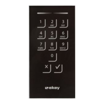
Product description System overview Fig. 1: Overview of the system 1 Code pad 2 Power supply 3 Control panel 4 Distributor 5 Motorised lock 6 Cable transfer 7 Connecting cable □ Code pad; Scope of delivery □ Control panel; □ Operating instructions, mounting instructions, wiring diagram;... - Page 6 If the code is entered incorrectly 3 times, there will be a 1-minute lock. If the code is then entered incorrectly a further 3 times, there will be a 15- minute lock. There will be a 15-minute lock each time the code is entered incorrectly after that.
-
Page 7: Control Panels
2 Button Fig. 3: Overview of ekey home CP mini 1 and ekey home CP micro 1 ekey home control panel mini 1: The upper status LED indicates whether the control panel is connected to the code pad. The lower status LED indicates when the relay switches. -
Page 8: Technical Specifications
Table 5: Button operation for ekey home CP micro 1 The control panel/code pad coupling takes place automatically in the case of the ekey home control panel micro 1, even if the code pad is replaced. Technical specifications Description Unit... -
Page 9: Installation
Digital inputs (only Quantity potential-free contacts may be connected) Table 7: Technical specifications: ekey home control panel mini 1 and ekey home control panel micro 1 Installation ATTENTION Mount and cable the product correctly before connecting power. Possible property damage! Do not connect the power supply beforehand! Mount the system in accordance with the supplied mounting instructions. -
Page 10: Commissioning
Commissioning the devices couples the control panel and the code pad Commissioning with one another. The following steps apply to the ekey home CP mini 1 devices and only. These steps are carried out automatically for the ekey home CP establishing micro 1. -
Page 11: Changing The Admin Code
Schritt Handlung Beschreibung Anzeige Press to start the The status LED lights up yellow process of entering on the left. the admin code. Enter the admin code on the keypad. Press . The status LED lights up green on the left. The status LEDs light up red. - Page 12 Step Action Description Display Press . The status LEDs light up yellow. The status LEDs light up red. The old admin code was not recognised. Enter the admin code from the beginning again. Enter the new admin code on the keypad. Press .
-
Page 13: Setting The Automatic Back-Illumination
Setting the The brightness threshold for switching on the automatic back-illumination automatic can be set using percentage values. By default, the brightness threshold back- is set to 10%. Enter the required percentage value: illumination □ = automatic back-illumination off; □ = brightness threshold settings between highly sensitive and highly insensitive. -
Page 14: Setting The Relay Switching Time
The system is in the admin menu. Step Action Description Display The status LED Press 5, and the lights up green number of the on the left. required mode. Press . The status LEDs light up green. The status LEDs light up red. - Page 15 Step Action Description Display The status LED Press 5, and the lights up green value of the required on the left. relay switching time. E.g. 1, 0, for 10 s. Press . The status LEDs light up green. The status LEDs light up red.
-
Page 16: Setting An Acoustic Signal For Opening
Step Action Description Display Something has been entered incorrectly. The signalling was not changed. Enter the admin code from the beginning again. No action Status LEDs are required. off. The optical and acoustic signalling to indicate that a button has been pressed has been set. -
Page 17: Storing The User Code
Storing the The system enables a maximum of 99 user codes to be enrolled. user code A user code is any pin code which is used for triggering an action on the control panel, e.g. opening a door. The user code may contain between 4 and 8 digits. -
Page 18: Use
Step Action Description Display Press . The status LEDs light up green. The status LEDs light up red. The two entries do not match. The user code was not stored. Enter the admin code from the beginning again. No action Status LEDs are required. -
Page 19: Deleting The User Code
NOTICE You can also open the door using the digital input (PIN 7, 8) on the ekey home CP mini 1. Deleting the You can delete individual user codes for a user. To do this, you require the user code user code to be deleted. - Page 20 the control panel, the coupling between the control panel and code pad is disconnected. Via the code pad Settings are reset to the default via the admin menu. To get to the admin menu, enter the admin code. See Entering the admin code, page 9. The system is in the admin menu.
- Page 21 The control panel and the code pad have been reset to the default settings. You can now re-commission the system. Via the digital input (ekey home control panel micro 1 only) The process of resetting to the default settings is triggered by the digital input.
-
Page 22: Updating The Software
If these suggestions fail to solve the problem, contact your reseller. If the system must be returned to ekey biometric systems GmbH, please ship it in suitable packaging. Improper packaging can lead to the warranty being voided. -
Page 23: Maintenance
All content, artwork and any ideas contained in these operating instructions are subject to applicable copyright laws. Any transmission, relinquishment or transfer of this content or parts thereof to any third party requires the prior written consent of ekey biometric systems GmbH. Translated documentation. 22│en... - Page 24 Austria Germany ekey biometric systems GmbH ekey biometric systems Deutschland GmbH Lunzerstraße 89, A-4030 Linz Liebigstraße 18, D-61130 Nidderau Tel.: +43 732 890 500 2500 Tel.: +49 6187 906 960 office@ekey.net deutschland@ekey.net Switzerland & Liechtenstein Eastern Adriatic region ekey biometric systems Est.
Need help?
Do you have a question about the home and is the answer not in the manual?
Questions and answers