Table of Contents
Advertisement
Quick Links
C
OM‐01233‐02
November 18, 2005
Rev. B 10‐08‐2013
INSTALLATION, OPERATION,
AND MAINTENANCE MANUAL
WITH PARTS LIST
0 SERIES PUMP
MODEL
04C52-B
THE GORMAN‐RUPP COMPANY D MANSFIELD, OHIO
www.grpumps.com
D
GORMAN‐RUPP OF CANADA LIMITED
ST. THOMAS, ONTARIO, CANADA
Printed in U.S.A.
e
2005 The Gorman‐Rupp Company
Advertisement
Table of Contents

Related Manuals for GORMAN-RUPP PUMPS 04C52-B


Summary of Contents for GORMAN-RUPP PUMPS 04C52-B
- Page 1 November 18, 2005 Rev. B 10‐08‐2013 INSTALLATION, OPERATION, AND MAINTENANCE MANUAL WITH PARTS LIST 0 SERIES PUMP MODEL 04C52-B THE GORMAN‐RUPP COMPANY D MANSFIELD, OHIO www.grpumps.com GORMAN‐RUPP OF CANADA LIMITED ST. THOMAS, ONTARIO, CANADA Printed in U.S.A. 2005 The Gorman‐Rupp Company...
- Page 2 Register your new Gorman‐Rupp pump online at www.grpumps.com Valid serial number and e‐mail address required. RECORD YOUR PUMP MODEL AND SERIAL NUMBER Please record your pump model and serial number in the spaces provided below. Your Gorman‐Rupp distributor needs this information when you require parts or service. Pump Model: Serial Number:...
-
Page 3: Table Of Contents
TABLE OF CONTENTS INTRODUCTION ..........PAGE I - 1 SAFETY ‐... - Page 4 TABLE OF CONTENTS (continued) PUMP MAINTENANCE AND REPAIR ‐ SECTION E ....PAGE E - 1 STANDARD PERFORMANCE CURVE ........PAGE E - 1 PARTS LISTS: Pump End Assembly...
-
Page 5: Introduction
0 SERIES OM-01233 INTRODUCTION Thank You for purchasing a Gorman‐Rupp pump. The following are used to alert maintenance per Read this manual carefully to learn how to safely sonnel to procedures which require special atten install and operate your pump. Failure to do so tion, to those which could damage equipment, and could result in personal injury or damage to the to those which could be dangerous to personnel:... -
Page 6: Safety - Section A
0 SERIES OM-01233 SAFETY ‐ SECTION A This information applies to 0 Series ba sic pumps. Gorman‐Rupp has no con trol over or particular knowledge of the power source which will be used. Refer This pump is designed to handle clear to the manual accompanying the power liquids containing specified entrained source before attempting to begin oper... - Page 7 OM-01233 0 SERIES Overheated pumps can cause severe Do not operate the pump against a burns and injuries. If overheating of the closed discharge valve for long periods pump occurs: of time. If operated against a closed dis 1. Stop the pump immediately. charge valve, pump components will 2.
-
Page 8: Installation - Section B
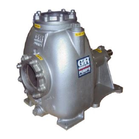
See Figure 1 for the approximate physical dimen some of the information such as mounting, line sions of this pump. OUTLINE DRAWING Figure 1. Pump Model 04C52-B INSTALLATION PAGE B - 1... -
Page 9: Preinstallation Inspection
OM-01233 0 SERIES PREINSTALLATION INSPECTION damage to the pump or components can occur if proper lifting procedures The pump assembly was inspected and tested be are not observed. Make certain that fore shipment from the factory. Before installation, hoists, chains, slings or cables are in inspect the pump for damage which may have oc... -
Page 10: Line Configuration
0 SERIES OM-01233 Line Configuration install it with the stem horizontal to avoid air pock ets. Keep suction and discharge lines as straight as Strainers possible to minimize friction losses. Make mini mum use of elbows and fittings, which substan If a strainer is furnished with the pump, be certain tially increase friction loss. -
Page 11: Suction Line Positioning
OM-01233 0 SERIES suction inlets so that they are separated by a dis NOTE tance equal to at least 3 times the diameter of the The pipe submergence required may be reduced suction pipe. by installing a standard pipe increaser fitting at the end of the suction line. -
Page 12: Alignment
0 SERIES OM-01233 enough to prevent clogging, but not so large as to Most couplings require a specific gap or clearance affect pump discharge capacity. between the driving and the driven shafts. Refer to the coupling manufacturer's service literature. ALIGNMENT Align spider insert type couplings by using calipers to measure the dimensions on the circumference of the outer ends of the coupling hub every 90_. -
Page 13: V-Belt Drive
OM-01233 0 SERIES V‐Belt Drive tio; overspeeding the pump may damage both pump and power source. When using V‐belt drives, the power source and the pump must be parallel. Use a straightedge along the sides of the pulleys to ensure that the pul leys are properly aligned (see Figure 5). -
Page 14: Operation - Section C
OM-01233 0 SERIES OPERATION - SECTION C Review all SAFETY information in Section A. coming liquid to evacuate the air. After the pump and piping system have completely filled, evacu Follow the instructions on all tags, labels and ate any remaining air pockets in the pump or suc decals attached to the pump. -
Page 15: Operation
OM-01233 0 SERIES three phase wires to change direction. If rotation is Liquid Temperature And Overheating incorrect on a single‐phase motor, consult the lit The maximum liquid temperature for this pump is erature supplied with the motor for specific instruc 160_ F (71_C). -
Page 16: Stopping
OM-01233 0 SERIES normal for bearings, and they can operate safely to inches (508,0 mm) or more of mercury. If it does at least 180_F (82_C). not, check for air leaks in the seal, gasket, or dis charge valve. Checking bearing temperatures by hand is inaccu rate. -
Page 17: Troubleshooting - Section D
OM-01233 0 SERIES TROUBLESHOOTING - SECTION D Review all SAFETY information in Section A. Before attempting to open or service the pump: 1. Familiarize yourself with this manual. 2. Disconnect or lock out the power source to ensure that the pump will remain inoperative. - Page 18 OM-01233 0 SERIES TROUBLE POSSIBLE CAUSE PROBABLE REMEDY PUMP STOPS OR Impeller or other wearing parts worn Replace worn or damaged parts. FAILS TO DELIVER or damaged. Check that impeller is properly RATED FLOW OR centered and rotates freely. PRESSURE (cont.) Impeller clogged.
-
Page 19: Preventive Maintenance
OM-01233 0 SERIES PREVENTIVE MAINTENANCE equipped) between regularly scheduled inspec tions can indicate problems that can be corrected Since pump applications are seldom identical, and before system damage or catastrophic failure oc pump wear is directly affected by such things as curs. - Page 20 PUMP MAINTENANCE AND REPAIR ‐ SECTION E MAINTENANCE AND REPAIR OF THE WEARING PARTS OF THE PUMP WILL MAINTAIN PEAK OPERATING PERFORMANCE. STANDARD PERFORMANCE FOR PUMP MODEL 04C52-B Based on 70_ F (21_ C) clear water at sea level Contact the Gorman‐Rupp Company to verify per...
- Page 21 OM-01233 0 SERIES PARTS PAGE SECTION DRAWING Figure 1. Pump Model 04C52-B PAGE E - 2 MAINTENANCE & REPAIR...
- Page 22 0 SERIES OM-01233 PARTS LIST Pump Model 04C52-B (From S/N 1399307 Up) If your pump serial number is followed by an “N”, your pump is NOT a standard production model. Contact the Gorman‐Rupp Company to verify part numbers. ITEM PART NAME...
- Page 23 OM-01233 0 SERIES PUMP AND SEAL DISASSEMBLY 4. Check the temperature before opening any covers, plates, or AND REASSEMBLY plugs. Review all SAFETY information in Section A. 5. Close the suction and discharge valves. Follow the instructions on all tags, label and de 6.
- Page 24 0 SERIES OM-01233 the cuts through the ring, and remove it from the seal plate. Use caution not to damage the seal pump casing. Use caution not to damage the plate bore when removing the wear ring. pump casing bore when removing the wear ring. Use caution not to damage the seal plate bore when removing the wear ring.
- Page 25 OM-01233 0 SERIES cleaning solvent. Inspect the parts for wear or dam age and replace as necessary. Most cleaning solvents are toxic and flammable. Use them only in a well ven tilated area free from excessive heat, sparks, and flame. Read and follow all Most cleaning solvents are toxic and precautions printed on solvent contain...
- Page 26 0 SERIES OM-01233 away from the shaft shoulders in shrinking. If Seal Reassembly and Installation movement has occurred, use a suitably sized sleeve and a press to reposition the bearings (Figures 1 and 2) against the shaft shoulders. Clean the seal cavity and shaft with a cloth soaked in fresh cleaning solvent.
- Page 27 OM-01233 0 SERIES RETAINER ROTATING ELEMENT SPRING SPRING O‐RING CENTERING WASHER STATIONARY SEAT IMPELLER IMPELLER SHAFT IMPELLER ADJUSTING SHAFT SHIMS SLEEVE SEAL BELLOWS PLATE Figure 2. Seal Assembly Carefully slide the assembled seal plate and sta tionary seal element over the shaft. Use caution not to nick or damage the stationary seat on the shaft threads.
- Page 28 0 SERIES OM-01233 To verify the impeller positioning, measure the impeller location (dimension E). Add or remove im pump casing and impeller as shown in Figure 3. peller adjusting shims (42) until dimension E is ob Use these measurements to calculate the required tained.
- Page 29 OM-01233 0 SERIES Refer to OPERATION, Section C, before putting the pump back into service. If grease is forced out around the shaft as LUBRICATION new grease is added, the bearing cavity is full and should be disassembled and cleaned immediately. Seal Assembly There are no provisions in the bearing cavity to The seal assembly is lubricated by the medium be...
- Page 30 For U.S. and International Warranty Information, Please Visit www.grpumps.com/warranty or call: U.S.: 419-755-1280 International: +1-419-755-1352 For Canadian Warranty Information, Please Visit www.grcanada.com/warranty or call: 519-631-2870 THE GORMAN‐RUPP COMPANY D MANSFIELD, OHIO GORMAN‐RUPP OF CANADA LIMITED ST. THOMAS, ONTARIO, CANADA...
Need help?
Do you have a question about the 04C52-B and is the answer not in the manual?
Questions and answers