
Related Manuals for Consilium ST650EX


Summary of Contents for Consilium ST650EX
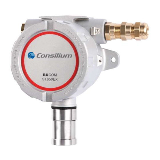
- Page 1 U S E R M A N U A L & T E C H N I C A L I N F O R M A T I O N ST650EX / ST650-CO ST350EX...
- Page 2 User manual & Technical information ST650EX / ST650-CO / ST350EX Version 3.16 – March 2022 All rights reserved ST650EX / ST650-CO / ST350EX v3.16...
- Page 3 Methane or 0-100% LEL Propane) gives a deviant reading. The ST650EX equipped with a catalytic bead sensor is not suitable for use in environments where continuous concentrations of gas are present. Continues concentrations of gas affects the life time of the sensor and creates a significant loss of sensitivity.
-
Page 4: Table Of Contents
Activation user menu ......................18 3.2.3 Settings menu ........................19 3.2.4 Front panel Status-LED ...................... 19 CALIBRATION ........................20 Calibration ST650EX / ST650-CO / ST350EX ................. 22 4.1.1 Calibration Zero level detector (ZERO calibration) ............23 4.1.2 Adjusting sensitivity detector (SPAN calibration).............. 24 Calibration using LC-display.................... - Page 5 ST650EX / ST650-CO / ST350EX v3.16...
-
Page 6: General
GENERAL The ST650EX sensing head is designed for the detection of flammable and combustible gasses. The ST650-CO is a specific version for the detection of Carbon Dioxide. The ST350EX sensing head is designed for the detection of flammable and toxic gasses at ppm level. The ST350EX/ST650EX can be integrated within a stationary gas detection system such as the Consilium CGS50/500, CGD50/500 systems. -
Page 7: Installation
Compare actual environmental specifications and regulations with the technical specifications of the used detector. Consilium offers several accessories to minimise the effect of rain, wind and particulate matter. The available accessories include: Splash guard tubing (electrically conductive PC with SS-fibres) ... - Page 8 / ST350EX should nevertheless be installed with a certain amount of distance from radio transmission equipment or similar devices. During installation the ST650EX / ST650-CO / ST350EX should be isolated from local ground. The unit should only be connected to ground through the screening of the connection cable (see chapter 2.2 - Cable requirements and Cable installation).
-
Page 9: Cable Requirements And Cable Installation
2.2 Cable requirements and Cable installation The signal cable for the ST650EX / ST650-CO / ST350EX should be a 3-core cable (flexible) with a tinned copper braid (at least 80% optical coverage) with a core diameter of 0.75 – 2.5mm The cable should feature a suitable isolation that meets industrial standards and is able to withstand severe weather and industrial conditions. -
Page 10: Maximum Cable Length
2.3 Maximum cable length The maximum cable length depends on input impedance of the system where ST650EX / ST650- / ST350EX is connected. The sum of the cable resistance and the input impedance is the total load impedance, and should not be greater than 400 Ω. -
Page 11: Power Supply
2.4 Power supply The power supply requirements for ST650EX / ST650-CO / ST350EX sensing head are stated in the technical specifications. To maintain optimal use and reliability under heavy industrial circumstances, the following requirements should be taken into account: The power supply of the control system should be a valid CE approved design with a maximum amount of protection against overload and power failure. -
Page 12: Electrical Connection
2.5 Electrical connection For the connection of the ST650EX / ST650-CO / ST350EX, the cable must be inserted in the proper manner. (See chapter 2.2 - Cable requirements and Cable installation). The signal cable must be connected to the power supply and the signal output of the sensing head. These are available on connector CON2 (see wiring diagram). - Page 13 WIRING DIAGRAM ST650EX-REMOTE: For mounting on high locations, the ST650EX is optionally available in a REMOTE version. This version features two junction boxes in which the sensor and the transmitter are mounted separately. The sensor has to be installed in a high location (where higher gas concentrations can be expected).
-
Page 14: Rfi (Emi)/Emc Protection
Use the ground connection of the gas detection system as star point grounded to earth. Mount the ST350EX/ST650EX on a non-conductive structure or base. Use an isolator when mounting on a conductive surface (like a steel H-profile, aluminium panel or swallow plate) to avoid connection to local electrical ground. -
Page 15: Operation
The target gas [Calibrated: #####] is mentioned on the label. More information about response factors, consult Consilium for advice. The ST650EX equipped with a catalytic bead sensor is not suitable for use in environments where continuous concentrations of gas are present. Continues concentrations of gas affects the life time of the sensor and creates a significant lose of sensitivity. -
Page 16: Functions
Output signal Each sensing head is supplied with a transmitter PCB with a 4- ST650EX / ST650-CO / ST350EX 20mA interface. This transmitter PCB transforms the sensor signal to an analogue 4-20mA signal. The sensing head has a number of predefined output levels. - Page 17 ST350EX/ST650EX sensing head. The RS-485 interface uses the MODBUS communication protocol. Do contact the Consilium service department for more information on this protocol. With the use of RS-485 serial communication up to 31 sensing heads are able to communicate through one connection cable without the use of additional amplifier equipment.
-
Page 18: Control And Lc-Display (If Applicable)
Status LED Select / enter button ‘Up’ button Type / model 3.2.1 Control buttons The ST650EX / ST650-CO / ST350EX features capacitive control buttons which can be operated through the glass cover without having to remove the lid. Use the buttons to navigate through the menu. -
Page 19: Settings Menu
3.2.3 Settings menu The settings menu offers a view of all user settings of the ST650EX / ST650-CO / ST350EX sensing head. Proceed as follows: Select SETTINGS The display will show the following: o SN: Serial number o TYPE: sensor type o RANGE: measurement range o UNITS: measurement units (ppm, ppb, LEL, etc.) -
Page 20: Calibration
6 months or more. The calibration frequency is directly related to the measurement range, the sensor, the type of gas and the environmental circumstances. All necessary calibration points are available on the PCB of the ST650EX / ST650-CO / ST350EX The ST650EX / ST650-CO / ST350EX feature 2 calibration settings: the “zero”... - Page 21 Example calibration set-up ST650EX / ST650-CO Example calibration set-up ST350EX: ST650EX / ST650-CO / ST350EX v3.16...
-
Page 22: Calibration St650Ex / St650-Co
Press the [CAL] key once to deactivate the calibration lock during 180 seconds. The status LED will flash green. The ZERO and SPAN potentiometers are now active (after 180 seconds the calibration lock will be automatically activated again). Transmitter PCB ST650EX / ST650-CO / ST350EX ST650EX / ST650-CO / ST350EX... -
Page 23: Calibration Zero Level Detector (Zero Calibration)
Wait until the sensor signal has stabilised. Adjust the zero level using the ZERO potentiometer to 4mA. Zero level ST650EX (IR / LEL version) When performing a zero level calibration no background gas concentration should be present. Use synthetic air when in doubt. -
Page 24: Adjusting Sensitivity Detector (Span Calibration)
The current value with this gas concentration is: I = 12.00mA Current REMARK: Always use calibration gas that is equal to the target gas. If the calibration gas is different from the target gas, contact Consilium. ST650EX / ST650-CO / ST350EX v3.16... - Page 25 Apply synthetic air with a flow of 20~30 l/h. Wait about 3 minutes for the sensor to stabilise. Adjust the current level using the SPAN potentiometer. Remove the calibration gas and the sensor signal should return to 4mA. ST650EX / ST650-CO / ST350EX v3.16...
-
Page 26: Calibration Using Lc-Display
4.2 Calibration using LC-display If the ST650EX / ST650-CO / ST350EX sensing head is equipped with a LC-display the unit can be calibrated using the front panel keys. The sensing head can be controlled using the control keys without removing the lid of the enclosure. -
Page 27: Adjusting Sensitivity (Span Calibration)
Repeat the SPAN calibration using the correct procedure until the message PASSED appears Check the sensor response time during a SPAN calibration. The response time must be within the specified T time. Ask Consilium for more details. (50) ST650EX / ST650-CO / ST350EX... -
Page 28: Troubleshooting Table
The following table offers the information needed to make a quick analyses of possible problems that may occur with the ST650EX / ST650-CO / ST350EX sensing head. In case of doubt and/or severe problems, do contact the Consilium service department or a Consilium authorised service centre. Malfunction... - Page 29 Detector cell defect. Check or replace the detector cell. Electronic defect Contact the Consilium Service department. Status-LED flashes GREEN Sensor is not connected Check the sensor and sensing (properly) head connections. The sensing head is not Calibrate the sensing head.
-
Page 30: Display Messages
ALARM The sensing head is working Ventilate the area and follow the GASTYPE properly. safety procedure applicable to Concentration level for low the area. %LEL alarm has been reached. ALARM HIGH ST650EX / ST650-CO / ST350EX v3.16... -
Page 31: Display Error Messages
GASTYPE The sensing head is not Calibrate the sensor (ZERO and (correctly) calibrated SPAN) %LEL ERROR Electronic defect Contact the Consilium Service department. GASTYPE Difference measured during Check sensor connections or current readback contact the Consilium Service department. %LEL... -
Page 32: Usage In Explosion Dangerous Areas
For more information about flameproof joints, please contact Consilium. The Consilium splashguard may store an ignition capable level of electrostatic charge in a IIC and a IIIC environment. The type labels on the enclosures may store an ignition capable level of electrostatic charge in a IIIC environment. -
Page 33: Technical Specifications
Outputs 4-20mA (3-wire), RS485 Modbus RTU (2 wire) Signal cable 3-wire shielded (5 incl. Modbus), 0.75 … 2.5 mm2 Load impedance max. 400Ω at 24 Vdc Cable gland Standard Brass, optional SS (thread M20x1.5) ST650EX / ST650-CO / ST350EX v3.16... - Page 34 Quality system ISO 9001 NEN-EN 50270 Compliance with EN 60079-29-1, EN50270, EN50271 - FTZU 17ATEX0094 IEC 60079-29-1 - IECEx FTZU 17.0022 Warranty 1 year Consilium reserves the right to alter these specifications without prior notice ST650EX / ST650-CO / ST350EX v3.16...
-
Page 35: Parts And Accessories
PARTS AND ACCESSORIES The following optional parts and accessories are available for the Consilium ST650EX / ST650- / ST350EX sensing heads: ST650EX: Spare gas sensor Part no. Range Description BUSENS D, type 3 1212200 0-100 %LEL CH Gas sensor for standard applications... - Page 36 Humidity bottle, to humidify the test gas (only applicable for Gas humidity bottle 1227300 SC# sensors, ST350EX) Flow regulator 9990600 Flow regulator brass, fixed flow 0,5 l/min Flow regulator 9990601 Flow regulator Stainless Steel, fixed flow 0,5 l/min ST650EX / ST650-CO / ST350EX v3.16...
-
Page 37: Appendices
APPENDICES Connection data The following diagram shows a view of the main PCB of the ST650EX / ST650-CO / ST350EX sensing head. The sensor is connected to the connections of connection block CON1 and CON4. The connection cable (power supply and measurement signal) and the RS485 communication cable are connected with the connections of connection block CON2. -
Page 38: Dip-Switch Settings
The following charts show the factory settings of the DIP-switch arrays. Changing the settings of a DIP-Switch influences the operation of the detector. Make sure the DIP-Switches are set according to the following charts. Contact Consilium when in doubt! The sensing head should be calibrated after each DIP switch change. - Page 39 For all versions: DIP-switch S1 Option: Standaard On: Yes LCD mode Off: No On: 20s. PID Duty cycle Off: 60s. sec. On: ppb PID ppb|ppm sensor Off: ppm DIP-switch S2 Option: Standaard ST650EX / ST650-CO / ST350EX v3.16...
-
Page 40: Dimensions And Mounting
Dimensions and mounting Front view Side view ST650EX / ST650-CO / ST350EX v3.16... -
Page 41: Certificates
Certificates The following certificate applies to the ST350EX / ST650EX / ST650-CO sensing heads: KIWA 16ATEX0008 X, IECEx KIWA 16.0003X With marking: IEC protection class Ex db IIC T6 Gb (compact & remote) Ex tb IIIC T85°C Db -20°C to +60°C amb. - Page 42 ST650EX / ST650-CO / ST350EX v3.16...
- Page 43 ST650EX / ST650-CO / ST350EX v3.16...
- Page 44 ST650EX / ST650-CO / ST350EX v3.16...
- Page 45 ST650EX / ST650-CO / ST350EX v3.16...
- Page 46 ST650EX / ST650-CO / ST350EX v3.16...
- Page 47 ST650EX / ST650-CO / ST350EX v3.16...
- Page 48 NOTES ST650EX / ST650-CO / ST350EX v3.16...
- Page 49 Service and maintenance of industrial gas detection products for both portable and stationary use. Dutch gas detection equipment for your health and safety. Consilium is a reliable and flexible gas detection partner since 1978. ISO 9001 ATEX, IECEx and MED certified ...
Need help?
Do you have a question about the ST650EX and is the answer not in the manual?
Questions and answers