Table of Contents
Advertisement
Quick Links
Advertisement
Table of Contents

Related Manuals for CubiScan 325


Summary of Contents for CubiScan 325
- Page 1 Cubiscan ® Operations and technical manual Version 2.0 Quantronix, Inc. Cubing and weighing systems 314 South 200 West Farmington, Utah 84025 U. S. A. Phone: 801.451.7000 Website: http://www.cubiscan.com Cubiscan 325 operations and technical manual...
- Page 2 The Cubiscan 325 should only be serviced by qualified personnel. Observe precautions for handling electrostatic sensitive devices when setting up or operating the Cubiscan 325. CAUTION Disconnect all power to the Cubiscan 325 before servicing or making any connections. WARNING E171537...
- Page 3 QUANTRONIX NEW PRODUCT Statement of Warranty. Quantronix, Inc.’s, warranty obligations are limited to the terms set forth below: Quantronix (hereinafter referred to as the “Seller”) warrants that its new product is in accordance with Seller’s published specifications (or those agreed upon with Buyer in writing) at the time of sale or lease and that it is free from non-cosmetic defects in materials and workmanship under normal use for a period of one (1) year from the date of sale or the commencement date under a written equipment lease or rental agreement (the “Warranty Period”).
- Page 4 Been operated beyond capacity. Not been manufactured by Seller including parts, accessories, or components which have been integrated into, used alongside of, or in conjunction with a product manufactured by Seller. TO THE EXTENT PERMITTED BY LAW, THIS WARRANTY AND THE REMEDIES SET FORTH ABOVE ARE EXCLUSIVE AND IN LIEU OF ALL OTHER WARRANTIES, REMEDIES AND CONDITIONS, WHETHER ORAL OR WRITTEN, STATUTORY, EXPRESS OR IMPLIED.
-
Page 5: Table Of Contents
Connecting power ........14 Turning on the Cubiscan 325 ....... 15 Connecting to a computer or network (optional) . - Page 6 Cubing and weighing using the touchscreen ....29 Zeroing the Cubiscan 325 ........35 Measuring with apparel mode .
- Page 7 CHAPTER 7 TROUBLESHOOTING ........64 No response when you turn power on......64 Scale readings are not accurate .
-
Page 8: List Of Figures
Cubiscan 325 in crate ........ - Page 9 Date and Time ......... . . 41 Date settings .
- Page 10 Gate Thresholds ......... 79...
-
Page 11: Product Description
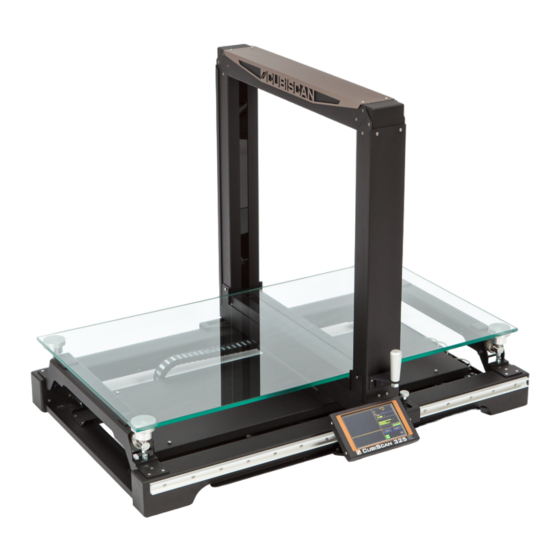
It has an integrated touchscreen display and outputs to a user-supplied PC. Capacity for irregular items can be measured up to 36 x 24 x 24 inches with a resolution of 0.05 inches. The Cubiscan 325 also includes an integrated, high-accuracy 50 x 0.005 lb scale. -
Page 12: Specifications
PRODUCT DESCRIPTION Figure 1 Cubiscan 325 Specifications Power requirements 100 – 240 VAC, 50 – 60 Hz Environmental Operating temperature: 14° to 104° F (-10° to 40° C) Humidity: 0 to 90% non-condensing Measuring sensor Infrared light beam Cubiscan 325... - Page 13 173 lbs (78.5 kg) User Interface Minimum PC Specifications: Windows 10/8/7/XP/95/98/NT/2000, Pentium II processor, 20 megabytes of disk space, screen resolution setting of 800 X 600 Cubiscan’s QBIT™ software can be used to interface with the Cubiscan 325. Cubiscan 325...
- Page 14 PRODUCT DESCRIPTION Display: Integrated TFT LCD touchscreen displays L, W, H, weight, unit of measure, 2D and height profile, and diagnostic codes. Outputs: Serial (1), Ethernet (1), USB-B (1), USB-A(3) Cubiscan 325...
-
Page 15: Setup
CHAPTER 2 SETUP This chapter provides instructions for assembling and setting up the Cubiscan 325. Perform the steps to set up the Cubiscan 325 in the following order: • Unpacking (page 5) • Placement (page 7) • Assembly (page 7) •... -
Page 16: Cubiscan 325 In Crate
Unpacking Figure 2 Cubiscan 325 in crate Examine the container and the Cubiscan 325 carefully for any damage. If, after unpacking, you discover any damage to the Cubiscan 325, contact the carrier immediately. Remove the wooden supports holding the Cubiscan 325 in place. -
Page 17: Placement
SETUP Placement Lift the Cubiscan 325 out of the shipping crate. It is best to have two people to do this because the Cubiscan 325 weighs about 173 lbs (78.5 kg) and may be awkward to handle. Placement The Cubiscan 325 is designed to be operated in a warehouse environment;... - Page 18 SETUP Assembling the Cubiscan 325 • Place the base assembly of the Cubiscan 325 on a stable surface. Make sure that the Cubiscan 325 is level. Adjust the leveling feet located in each corner if necessary. • An optional cart, custom-designed for the Cubiscan 325, is available from Cubiscan.
-
Page 19: Removing The Shipping Material
The front of the gate (the side with the handle attached), must face the front of the system. If this side of the gate is not in front, the Cubiscan will not work properly. 2. Before securing the gate in place, remove the red brackets at the bottom of the gates. -
Page 20: Red Brackets
SETUP Assembling the Cubiscan 325 Figure 5 Red brackets 3. Secure the gate to the gate tray using the eight Phillips screws provided. The four slot screws may already be screwed into the gate. If they are, you only need to screw four Phillips screws into place. -
Page 21: Placing The Glass Platform
SETUP Assembling the Cubiscan 325 Placing the glass platform 1. Place the four load cell balls in the load cell cups. Figure 7 Load cell balls 2. Remove the glass cubing and weighing platform from the cardboard box that was in the shipping crate. You will need to screw the four ball sockets into place. -
Page 22: Attaching The Touchscreen
SETUP Assembling the Cubiscan 325 3. Carefully place the glass platform on the load cells, as shown below. It is best to use two people to move the glass. Avoid placing excessive force or stress on the load cells. Figure 9... -
Page 23: Touchscreen Attached
SETUP Assembling the Cubiscan 325 2. Attach the touchscreen to the mount on the front of the Cubiscan. Secure the touchscreen using the two wing nuts. Figure 11 Touchscreen attached 3. Plug the display cable into the back of the touchscreen. -
Page 24: Loosen The Gate Stop
Figure 12 Gate stop Connecting power 1. Locate the AC power cord (supplied) and connect it to the power connection on the right side of the controller box as shown below. Figure 13 Connecting power Cubiscan 325... -
Page 25: Turning On The Cubiscan 325
Specific procedures must be followed each time you turn on the Cubiscan 325, as follows: 1. Make sure there are no packages or other objects on the Cubiscan 325 platform. 2. Make sure the gate is in the home position (right-hand side). -
Page 26: Connecting To A Computer Or Network (Optional)
Cubiscan for information on available software. Or, refer to the Communications Protocol. • Connect the Cubiscan 325 to a PC using a USB cable (not provided) through the USB port on the controller box. • Connect the Cubiscan 325 to a PC through the RS-232-C serial port on the controller box. -
Page 27: Connecting To A Computer Via Ethernet
Connecting to a computer via Ethernet This section describes how to use Ethernet to connect a computer to the Cubiscan 325 (recommended method). Use Cubiscan® Qbit software (refer to the Qbit User Guide) or the touchscreen options (see CHAPTER 4 “CONFIGURATION”) to configure... -
Page 28: Installation Bubble
If you clicked on the installation bubble, the following window will open. Figure 17 Installation process bubble • Once the driver has finished the installation process it will report that the adapter is ready to use. Figure 18 Adapter is ready to use Cubiscan 325... -
Page 29: Status Window
Subnet mask of the adapter. You can access these network settings by completing the following steps: 1. Under Control Panel > Network and Internet > Network and Sharing Center locate and click on the correct connection to bring up the status window. Figure 19 Status window Cubiscan 325... -
Page 30: Connecting To A Computer Via Usb
This section describes how to use a USB connection to connect a computer to the Cubiscan 325. If you are using the USB cable (not supplied) connection: 1. Connect the USB cable to the Cubiscan 325’s USB port located on the controller box, as shown in Figure 2. -
Page 31: Connecting To A Computer Via Serial (Rs-232-C)
Make sure that the cable does not interfere with the scale. 2. Connect the serial cable to the Cubiscan 325’s serial port, as shown in Figure 3. Locate a free RS-232-C serial port on your computer. Refer to your computer's documentation, if necessary, to identify the ports. -
Page 32: Installing Qbit (Optional)
Barcode Scanner Mount (optional) For your convenience, the barcode mounting assembly for the Cubiscan 325 is designed to mount on either the left or right side of the cart simply by flipping the mounting unit over to the correct orientation. -
Page 33: Left-Hand Mounting
As before, ensure that the mounting bracket is situated so the top mounting surface slopes downward toward the front of the cart. Figure 23 Right-hand mounting Replace the side panel to its original position. Cubiscan 325... -
Page 34: Mounting Barcode Base
Depending on the orientation, the cord will wrap on the left or right side of the mount as seen in Figure 25. Use cable ties to secure the cord to the mount. Run the cord through the gap in the mount to the controller unit. Figure 25 Cord winding Cubiscan 325... -
Page 35: Setup Checklist
(page 9) 4. Is the Cubiscan 325’s glass platform free moving? The Cubiscan 325 should not be pushed up against a wall and no object, cable, etc., should be resting on it or against it. 5. Has the Ethernet, RS-232, or USB cable been attached to the... - Page 36 SETUP Setup checklist Cubiscan 325...
-
Page 37: Operation
“Zeroing the Cubiscan 325” on page Do not lean on or touch the Cubiscan 325 glass platform or the object while the object is being measured and weighed. Any kind of contact with the platform during the measurement process can alter the weight or sensor reading. -
Page 38: Cubiscan 325 Touchscreen
OPERATION Cubiscan 325 touchscreen Cubiscan 325 touchscreen You can use the Cubiscan 325 touchscreen (below) to configure and control the Cubiscan 325 as well as display measurement results. Figure 26 Cubiscan 325 touchscreen Touchscreen care Never use a sharp or hard-tipped object to tap on the touchscreen. You can tap lightly on the screen with your fingertip, or you can use the eraser end of a pencil or a stylus with a soft point. -
Page 39: Cubing And Weighing
0.1 inch (refer to “Specifications” on page 2 specifications and size limitations). Objects are measured by the infrared light beams on the Cubiscan 325’s gate by moving the gate over the object on the platform. Refer to the appropriate following section for instructions. -
Page 40: Measurement Display
Filter mode Enable filter mode by tapping on the icon. In filter mode the Cubiscan 325 will detect the object with the most contiguous pixels (indicating the Cubiscan 325... -
Page 41: Filter Mode
“Measuring with apparel mode” on page Menu Tap the menu icon in the upper left corner of the machine to open the menu bar. From here you can select from the various options (Version, Cubiscan 325... - Page 42 Take the following steps to measure and weigh an item using the touchscreen: 1. Verify that the Cubiscan 325 scale is at zero. The zero (>0<) indicator should be highlighted. 2. Place the object on the glass platform. The zero (>0<) indicator will go out.
-
Page 43: Measuring Gate
OPERATION Cubing and weighing Do not lean on or touch the Cubiscan 325 platform or the object while an object is being measured. Any kind of contact with the platform during the measurement process can alter the weight or sensor reading. -
Page 44: Measurement Display
Waiting for confirmation from the server that data was sent and received. To enable/disable this function, see “Server Acknowledge” on page • Remeasuring without the compression plate in the case of apparel mode. To enable/disable this function, see “Apparel” on page Cubiscan 325... -
Page 45: Zeroing The Cubiscan 325
Tap the [>0<] button on the touchscreen to “zero” the Cubiscan 325. This sets all empty measurements and weight to zero. The weight when the platform is empty must be set to zero for the Cubiscan 325 to operate properly. The Cubiscan 325 tries to zero itself automatically. However, you may need to use this option in the following circumstances. -
Page 46: Measuring With Apparel Mode
4. Pass the gate over the apparel to complete the height measurement with the compression plate. Notice in the height display panel, a red line separates the boundary between the compression plate and the apparel. This allows for a more accurate measurement of height during Cubiscan 325... -
Page 47: Apparel Mode: First Pass
Apparel mode: first pass 5. Remove the compression plate, and pass the gate over the apparel again. Measurements will now display in the left-side panel with their respective adjustments. Notice in the height display, the red line is Cubiscan 325... -
Page 48: Apparel Mode: Second Pass
Measuring with apparel mode present, indicating the compressed height, along with a green line, indicating the non-compressed height. Figure 35 Apparel mode: second pass 6. Finish the measurement by performing any additional actions such as scanning the barcode. Cubiscan 325... -
Page 49: Configuration
CHAPTER 5 “CALIBRATION”. If you have a computer connected to the Cubiscan 325 with Qbit installed, you can use Qbit to set up the measurement and dimensional weight units, select the Cubiscan 325 communications port, perform calibration, and other functions. -
Page 50: General Settings
Images posted from the machine may be set to XY BMP, XY&Z BMP, or disabled. Machine ID Optional Machine ID may be set for the Cubiscan. This may be useful in a facility where data is tracked from more than one Cubiscan. Password Optional password Protection for the touchscreen is available. -
Page 51: Date And Time
To set the date and time complete the following steps: 1. Tap the menu icon in the upper left corner of the home screen. 2. From the menu side panel, select SETTINGS. 3. Scroll down to the DATE AND TIME Figure 37 Date and Time Cubiscan 325... -
Page 52: System Reset
System Reset In the event that settings need to be reset back to factory defaults, the Cubiscan 325 has a system reset. By initiating system reset, all settings including custom settings will be reset back to their initial presets. Reseting... -
Page 53: Measure Settings
3. Scroll down to SYSTEM RESET. 4. Tap [RESET TO FACTORY DEFAULTS]. Measure Settings The following options can be used to configure your Cubiscan 325. Settings exist for configuring measurements and the interface, allowing you to setup a measurement system that meets your needs and preferences. -
Page 54: Measure Settings
Item End Toggle item end detection on or off. This will enable an error message if a measurement is started but no end is detected. Detection Cubiscan 325... -
Page 55: Units
Will automatically set to the selected Dim-Factor (domestic or international). Below, the preconfigured factor will be displayed for the given units and dim-factor selected. This factor may be adjusted as needed by entering the desired factor in the text field. Cubiscan 325... -
Page 56: Qr Code
CONFIGURATION Measure Settings QR Code The Cubiscan 325 offers a QR Code that may be displayed on the touchscreen, providing the dimensioning information. This may be used in conjunction with third party software as a means of capturing the dimensioning information. -
Page 57: Filter
When Auto-Off is selected, the operator will need to manually select the check box for each measurement. When Lock-On is selected, the check box will always be checked and the Cubiscan 325 will take measurements in filter mode until the mode option is changed. Cubiscan 325... -
Page 58: Apparel
The results will display the average height, length, and width of an item. Mode This drop-down menu offers different modes for using the apparel method feature. The options are disabled, enabled, auto-off, and lock-on. When Disabled is selected, the check box will not be visible on the home screen. Cubiscan 325... -
Page 59: Connection
This field displays the height (85 mm) of the compression plate provided by Cubiscan. If a different compression plate is used, you’ll need to change the value in this field so that the Cubiscan 325 can subtract the height of the compression plate from measurements in which it is used. -
Page 60: Ethernet Settings
Ethernet Settings The Ethernet Settings field allows you to select the Ethernet settings for the Cubiscan. The following information is displayed to help you connect with the CS 325: MAC Address, IP Address, Subnet, and Gateway. Figure 46 Connection Enable Ethernet Toggling this option enables or disables the Cubiscan 325’s ability to... -
Page 61: Web-Server
29 Area Toggle to enable/disable the area calculation function. When enabled, the Cubiscan 325 will calculate an estimate of the area of the object in the XY Calculations plane. This calculation is not meant to be an accurate representation of area, but is an estimate used for tracking purposes. -
Page 62: Post
The Post section provides a toggle to enable or disable the posting of data. Figure 49 Connection - post With post enabled, the following information will be needed for the Cubiscan to post data: Enable Post Toggle to enable/disable posting of measurement data. Post Debug Toggle to enable/disable posting of debug data Host Enter host address of network to post data. -
Page 63: Scale Setting
CONFIGURATION Scale Setting Scale Setting The Cubiscan 325 has a built in scale. To configure the scale, complete the following steps: 1. Tap the menu icon in the upper left corner of the home screen. 2. From the menu side panel, select SCALE. - Page 64 Increasing the averaging will increase the time to complete measurement. Filtering Adjusts the intensity of filtering during weighing. The greater the number, the more accurate the measurement. Increasing the filtering will increase the time to complete measurement. Cubiscan 325...
-
Page 65: Calibration
Calibrate the Cubiscan 325 if you have problems cubing and weighing after assembly and setup. • Calibrate the Cubiscan 325 if it is subjected to any type of mechanical shock or collision with a heavy object. • Calibrate the Cubiscan 325 as part of a regular maintenance schedule. -
Page 66: Calibrating The Scale
Take the following steps to calibrate the Cubiscan 325 scale. When calibrating the scale, the Cubiscan 325 must be stable with no movement of the platform such as that caused by vibration or air. -
Page 67: Scale Screen
3. The following screen is displayed. Follow the instructions as displayed. Figure 53 Second scale calibration screen 4. Enter the calibration weight value in the first text field. Then select the units in the dropdown below the field. Cubiscan 325... -
Page 68: Calibrating Height
7. Once the scale is zeroed, place the calibration weight on the platform and tape [Scale Calibration]. A message will display when calibration is complete. Figure 55 Scale calibration complete Calibrating height To calibrate the height using the touchscreen, proceed as follows. Cubiscan 325... -
Page 69: Home Screen
The Height (in) and Height (mm) fields display live values and will change when the 5" box has been placed in the gate. The Offset (mm) field will display the offset value after tapping the [Calibrate Height] button. Cubiscan 325... - Page 70 Calibrating height Follow the instructions displayed under the GATE HEIGHT CALIBRATION section to finish gate calibration. 4. Move the Gate to the middle of the glass. 5. Place the 5” calibration cube inside the gate and tap [Calibrate Height]. Cubiscan 325...
-
Page 71: Maintenance
Cubiscan 325. Routine maintenance and careful handling will help keep the Cubiscan in good operating condition and prevent service calls or repairs. Precautions The Cubiscan 325 should not be subjected to extremes in temperature or humidity, nor should it be subjected to excessive vibration. For environmental recommendations, see “Placement”... -
Page 72: Removing The Controller
MAINTENANCE Removing the controller Removing the controller If you suspect that there is a problem with the Cubiscan 325 controller, first review the Troubleshooting chapter and take any recommended action. If the problem persists, contact Cubiscan Technical Assistance at 801.451.7000 for assistance. -
Page 73: Drawing Of Controller
7. Verify that all cables have been removed from the controller, then lift the box up and pull it out sideways (to the right) until it is clear of the metal frame of the Cubiscan 325. Cubiscan 325... -
Page 74: Troubleshooting
If problems continue, review the following sections for more information. No response when you turn power on If there is no response when you power on the Cubiscan 325, do the following: 1. Verify that the AC power cord is pressed firmly into the power socket. -
Page 75: Scale Readings Are Not Accurate
3. Make sure the scale setting in menu is set to Internal. See “Scale Setting” on page 4. Move the Cubiscan 325 if it is located close to open freight doors or where air is blowing on it. Extreme air flow can affect the accuracy of the Cubiscan 325. Refer to “Placement”... - Page 76 If you receive one of these messages, verify the following. 1. Is the Cubiscan 325 turned on and securely connected to power? 2. Is the network cable connected to both the Cubiscan 325 and the computer or network, and are both connections secure? 3.
-
Page 77: Version
Figure 60 About version The following information will display about the Cubiscan 325 and its Firmware. MAC Address The Media Access Control (MAC) address. -
Page 78: Firmware
TROUBLESHOOTING Version Operation The total hours of operation for the Cubiscan 325. Hours Firmware The firmware version used for the main controller, including build and Kernel. Firmware This section displays the firmware version used for the main controller, including build and kernel. This information is useful when a technician is diagnosing issues that may arise from the Cubiscan firmware. -
Page 79: Soft Reset
Diagnostics Soft Reset There may be an occasion that the Cubiscan 325 will need a soft reset. This is a reset of the operating system without shutting off the power to the machine. A soft reset may be necessary if the operating system is not working as intended or is running sluggish. -
Page 80: Diagnose Gate
TROUBLESHOOTING Diagnostics 2. On the gate screen, tap [Diagnose Gate] in the Gate Diagnostics section. Figure 63 Diagnose Gate Cubiscan 325... -
Page 81: Gate Diagnostic
Diagnostics The four LED beam bars now shown on the left-side of the display represent the LED beams that the Cubiscan 325 uses to measure objects. This is a useful screen for determining the functionality of the LED beams. Figure 64... -
Page 82: Gate Options
LEDs that are negatively affecting LEDs measurements. Figure 66 Latched LEDs Mask Options Under the section Mask Options are controls for masking LEDs for both the width and height. When masked, an LED will not transmit or receive. This Cubiscan 325... -
Page 83: Mask Options
Tap [Auto-Mask Latched LEDs] to mask any LEDs that are currently latched. Masked LEDs will show as black bars in the displayed beams. Latched LEDs Unmask All Tap [Unmask All LEDs] to remove the mask from all LEDs. LEDs Cubiscan 325... -
Page 84: Latched Leds
LEDs Figure 69 Latched LEDs Masking LEDs Issues may arise in the measuring process that prevent the CS 325 from properly identify the smallest bounding square around an object. Figure 70 Errors in measuring Causes of errors in measurement may include: •... -
Page 85: Gate Diagnostic
Gate Diagnostic 3. Toggle on the Enable Latch. Figure 72 Enable latch 4. Move the gate across the area of the platform that is having issues. Yellow lines in the beam display signify the LEDs that are affected. With Cubiscan 325... -
Page 86: Latched Leds
5. Tap [Auto-Mask Latched LEDs] to mask the latched LEDs. Alternatively, Tap [Mask One LED] to manually enter the location of the LEDs you wish to mask. Tap [Show Latched LEDs] to find the width and height locations of the latched LEDs. Figure 74 Auto-Mask Cubiscan 325... -
Page 87: Masked Measurement
TROUBLESHOOTING Diagnostics 6. With the LEDs masked, you may begin dimensioning without the affected LEDs. Figure 75 Masked measurement Cubiscan 325... -
Page 88: Gate Settings
2. Tap [Scan All Thresholds]. This will scan the LED curtain to calculate new sensor thresholds. Along each of the four columns, the number values would be the same. If there is a discrepancy or if there is no Cubiscan 325... - Page 89 TROUBLESHOOTING Diagnostics response from the gate or any of its boards, contact a Cubiscan technician to help assess the problem. Figure 77 Gate thresholds Cubiscan 325...
- Page 90 APPENDIX A PARTS LIST Following is a list of parts that can be purchased for the Cubiscan 325 as spare parts or if replacement is necessary. Part No. Description Quantity/Unit 10083 AC power cord 10084 Scale card PCB 12344 1/2'' Diameter ball...
Need help?
Do you have a question about the 325 and is the answer not in the manual?
Questions and answers