Table of Contents
Advertisement
Quick Links
Advertisement
Table of Contents
Troubleshooting

Subscribe to Our Youtube Channel
Related Manuals for Supermicro SuperServer SYS-421GE-TNHR2-LCC


Summary of Contents for Supermicro SuperServer SYS-421GE-TNHR2-LCC
- Page 1 SuperServer ® SYS-421GE-TNHR2-LCC USER’S MANUAL Revision 1.0...
- Page 2 State of California, USA. The State of California, County of Santa Clara shall be the exclusive venue for the resolution of any such disputes. Supermicro's total liability for all claims will not exceed the price paid for the hardware product.
- Page 3 If you have any questions, please contact our support team at: support@supermicro.com This manual may be periodically updated without notice. Please check the Supermicro website for possible updates to the manual revision level. Secure Data Deletion A secure data deletion tool designed to fully erase all data from storage devices can be found on our website: https://www.supermicro.com/about/policies/disclaimer.cfm?url=/wdl/utility/...
-
Page 4: Table Of Contents
Preface Contents Chapter 1 Introduction 1.1 Overview ..........................9 1.2 System Features ........................10 Front View .........................10 Control Panel .........................11 NVMe SSD Drive Indicators ..................12 Rear View ..........................13 Power Supply Indicator ....................14 Input/Output Panel ......................14 Top View, Motherboard Tray and Switch Modules ............15 Top View: GPU Tray ......................16 1.3 System Block Diagram .......................17 1.4 Motherboard Layout ......................19... - Page 5 Preface Chapter 3 Maintenance and Component Installation 3.1 Removing Power ........................30 3.2 Accessing the System ......................30 Removing the Top Cover ....................30 Mid-chassis Cover ......................30 3.3 Memory Support and Installation ..................32 Memory Support ........................32 DDR5 Memory Support for 5 Gen. Intel Xeon Scalable Processors ......32 Memory Population for the X13DEG-M Motherboard (with 32 DIMM Slots) ....34 Memory Slots .........................36 DIMM Installation ......................38...
- Page 6 Preface Chapter 5 Software 5.1 Microsoft Windows OS Installation ..................59 5.2 Driver Installation ........................61 5.3 BMC ............................62 5.4 Logging into the BMC (Baseboard Management Controller) ..........62 Chapter 6 Optional Components 6.1 Storage Protocols Supported .....................63 6.2 Power Supply Configurations .....................64 6.3 TPM Security Module ......................64 Chapter 7 Troubleshooting and Support 7.1 Information Resources .......................65...
- Page 7 Preface 7.8 Where to Get Replacement Components ................74 7.9 Reporting an Issue ......................74 Returning Merchandise for Service ...................74 7.10 Feedback ...........................74 7.11 Contacting Supermicro .......................75 Appendix A Standardized Warning Statements for AC Systems Appendix B System Specifications...
- Page 8 San Jose, CA 95131 U.S.A. Tel: +1 (408) 503-8000 Fax: +1 (408) 503-8008 Email: marketing@supermicro.com (General Information) Sales-USA@supermicro.com (Sales Inquiries) Government_Sales-USA@supermicro.com (Gov. Sales Inquiries) support@supermicro.com (Technical Support) RMA@supermicro.com (RMA Support) Webmaster@supermicro.com (Webmaster) Website: www.supermicro.com Europe Address: Super Micro Computer B.V.
-
Page 9: Chapter 1 Introduction
4U rackmount; 17.2 x 7 x 29 in. / 437 x 178 x 737 mm (WxHxD) Notes: A Quick Reference Guide can be found on the product page of the Supermicro website. The following safety models associated with the SYS-421GE-TNHR2-LCC have been certified as compliant with UL and CSA: GP401LC-Q52X13 and GP401LC-52. -
Page 10: System Features
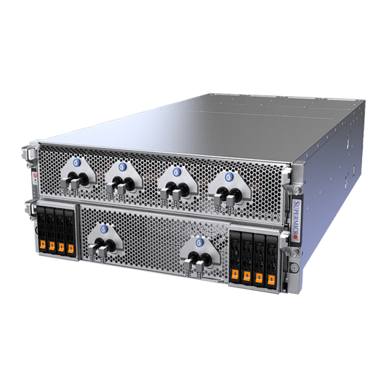
Chapter 1: Introduction 1.2 System Features The following views of the system display the main features. Please refer to Appendix B additional specifications. Front View Liquid Cooling Ports Control Panel Service Tag Eight 2.5" Hot-swap NVMe/SATA3 Drive Bays Figure 1-1. Front View Front Features Feature Description... -
Page 11: Control Panel
Chapter 1: Introduction Control Panel The switches and LEDs located on the control panel are described below. Power Button Universal Information LED Power LED Drive Activity LED NIC1 LED NIC2 LED Information LED Power Fail LED Figure 1-2. Control Panel Control Panel Features Features Description... -
Page 12: Nvme Ssd Drive Indicators
Chapter 1: Introduction Information LED Color, Status Description An overheat condition has occurred. Continuously on and red (This may be caused by cable congestion.) Blinking red (1 Hz) Fan failure, check for an inoperative fan. Solid blue UID has been activated locally to locate the server in a rack environment. UID has been activated remotely using IPMI to locate the server in a rack Blinking blue (300 msec) environment. -
Page 13: Rear View
Chapter 1: Introduction Rear View Power Supply Modules PCIe Slots (FHHL) PCIe Slots (LP) I/O Panel PCIe Slots (FHHL, optional) Figure 1-3. System: Rear View System Features: Rear Feature Description Power Supply Modules Four 5250 W (2+2) power supplies PCIe Slots (FHHL) Two FHHL (full-height, half-length) PCIe 5.0 x16 slots PCIe Slots (HHLP) Eight HH (half-height or "low profile") PCIe 5.0 x16 slots... -
Page 14: Power Supply Indicator
Chapter 1: Introduction Power Supply Indicator Power Supply Status Indicator LED Color and State Power Supply Condition Solid Green Indicates that the power supply is on and working Blinking Green Indicates the system is off Solid Amber Indicates failure or needs attention No AC power to module Input/Output Panel VGA Port... -
Page 15: Top View, Motherboard Tray And Switch Modules
Chapter 1: Introduction Top View, Motherboard Tray and Switch Modules PCIe Switches Processors DIMM Slots M.2 Slots System Fans Figure 1-5. Motherboard Tray: Top View System Features: Top Feature Description PCIe Switches Four PCIe switches M.2 Slots Two slots for PCIe 3.0 x2 M.2 NVMe (from PCH) DIMM Slots 32 DIMM ECC DDR5 designed for up to 4800 MT/s (1DPC) / 4400MT/s (2DPC) Processors... -
Page 16: Top View: Gpu Tray
Chapter 1: Introduction Top View: GPU Tray GPUs NVIDIA NVSwitches Figure 1-6. Motherboard Tray: Top View System Features: Top Feature Description NVIDIA NVSwitches Four NVIDIA NVSwitches GPUs Eight NVIDIA HGX H100 GPUs... -
Page 17: System Block Diagram
Chapter 1: Introduction 1.3 System Block Diagram Figure 1-7. System Block Diagram... - Page 18 Chapter 1: Introduction Note: The GPU numbering is based on BMC interface numbering. See the below GPU mapping table for more information. GPU Mapping Table GPU Socket BMC Interface Linux OS Numbering Linux OS Address Numbering Numbering GPU 1 GPU 1 GPU 2 4C:00.0 GPU 2...
-
Page 19: Motherboard Layout
Chapter 1: Introduction 1.4 Motherboard Layout Below is a layout of the X13DEG-M motherboard with jumper, connector and LED locations shown. See the table on the following page for descriptions. For detailed descriptions, pinout information and jumper settings, refer to Chapter 4 or the Motherboard Manual. -
Page 20: Quick Reference Table
Chapter 1: Introduction Quick Reference Table Jumper Description Default Setting JBT1 CMOS Clear Open (Normal) JDBG1, JDBG2 For manufacturing use only Open (Normal) PSUs and redundant PSUs support JSWID1 and JSWID2: Pins 1-2 (Closed) JSWID1, JSWID2 (For manufacturing use only) Two PSUs and two redundant PSUs JVRM1, JVRM2 For manufacturing use only... - Page 21 Trusted Platform Module/Port 80 Connector P54V_JPWR1 54 V Power Output Connector Note: For details on how to configure Network Interface Card (NIC) settings, please refer to the Network Interface Card Configuration User's Guide posted on our website under the link: http://www.supermicro.com/support/manuals/.
-
Page 22: Motherboard Block Diagram
Chapter 1: Introduction Motherboard Block Diagram X13DEG-M CPU2-A1 CPU2-B1 CPU2-C1 CPU2-D1 CPU1-D1 CPU1-C1 CPU1-B1 CPU1-A1 MC0 = A & B VR14 VR14 MC1 = C & D 550A Iccmax 8 PHASE 8 PHASE MC2 = E & F 185A IccTDC 350W 350W SPR:16GT/19.2GT... -
Page 23: Chapter 2 Server Installation
Chapter 2: Server Installation Chapter 2 Server Installation 2.1 Overview This chapter provides advice and instructions for mounting your system in a server rack. If your system is not already fully integrated with processors, system memory etc., refer to Chapter 4 for details on installing those specific components. -
Page 24: Rack Precautions
Chapter 2: Server Installation Rack Precautions • Ensure that the leveling jacks on the bottom of the rack are extended to the floor so that the full weight of the rack rests on them. • In single rack installations, stabilizers should be attached to the rack. In multiple rack installations, the racks should be coupled together. -
Page 25: Mechanical Loading
Chapter 2: Server Installation Mechanical Loading Equipment should be mounted into a rack so that a hazardous condition does not arise due to uneven mechanical loading. Circuit Overloading Consideration should be given to the connection of the equipment to the power supply circuitry and the effect that any possible overloading of circuits might have on overcurrent protection and power supply wiring. -
Page 26: Installing The Mounting Rails On The Rack
Chapter 2: Server Installation Installing the Mounting Rails on the Rack Installing the Mounting Rails 1. Confirm that the left and right outer rails have been correctly identified. 2. Install the rails using the screws that come with kit as shown in the illustration below. 3. -
Page 27: Rack-Mounting The Chassis
Chapter 2: Server Installation Rack-Mounting the Chassis After the rails are installed on the rack, the chassis can now be mounted. Note that it is heavy and requires two to three people to lift. Installing the Chassis into a Rack 1. -
Page 28: Unmounting The Chassis From The Rack
Chapter 2: Server Installation Unmounting the Chassis from the Rack Caution: The chassis is heavy and requires two to three people to lift it out. Removing the Chassis 1. Remove all screws that are securing the chassis from its sides. 2. -
Page 29: Connecting To A Coolant Distribution Unit (Cdu)
Chapter 2: Server Installation Connecting to a Coolant Distribution Unit (CDU) Caution: The chassis is heavy and requires two to three people to lift it out. The CSE-GP401 chassis uses a liquid-cooling solution to maintain operational temperature. The coolant from the chassis is circulated out to an external Coolant Distribution Unit (CDU) using specialized pipes and tubes, where it is cooled through a cooling tower or cooling unit, and circulated back to the CDU and back to the chassis. -
Page 30: Chapter 3 Maintenance And Component Installation
Chapter 3: Maintenance and Component Installation Chapter 3 Maintenance and Component Installation This chapter provides instructions on installing and replacing main system components. To prevent compatibility issues, only use components that match the specifications and/or part numbers given. Installation or replacement of most components require that power first be removed from the system. - Page 31 Chapter 3: Maintenance and Component Installation Lift the cover Remove Screws Figure 3-1. Removing the Chassis Cover Caution: Except for short periods of time, do not operate the server without the cover in place. The chassis cover must be in place to allow proper airflow and prevent overheating.
-
Page 32: Memory Support And Installation
Chapter 3: Maintenance and Component Installation 3.3 Memory Support and Installation Note: Check the Supermicro website for recommended memory modules and updates on possible memory support. Important: Exercise extreme care when installing or removing DIMM modules to prevent any possible damage. - Page 33 Chapter 3: Maintenance and Component Installation DDR5 Memory Support for the 5 Gen. Intel Xeon Scalable Processors Speed (MT/s); Voltage (V); DIMM Per Channel (DPC) DIMM Density and DIMM Ranks Per DIMM Capacity Type & Data Width 1DPC (Note) 2DPC (Stack) 16 Gb 24 Gb...
-
Page 34: Memory Population For The X13Deg-M Motherboard (With 32 Dimm Slots)
CPU2: P2-DIMMA1 / P2-DIMMA2 / P2-DIMMB1 / P2-DIMMB2 / P2-DIMMC1 / P2-DIMMC2 / P2-DIMMD1 / P2-DIMMD2 / P2-DIMME1 / P2-DIMME2 / P2-DIMMF1 / P2-DIMMF2 / P2-DIMMG1 / P2-DIMMG2 / P2-DIMMH1 / P2-DIMMH2 Note: This memory configuration is recommended by Supermicro for optimal memory performance. Please use this configuration to maximize your memory performance. - Page 35 Chapter 3: Maintenance and Component Installation DDR5 Memory Population Table for HMB CPU 32-DIMM Motherboards 1 CPU: Memory Population Sequence 1 CPU & 1 DIMM P1-DIMMA1 or P1-DIMME1 P1-DIMMA1 / P1-DIMMG1 1 CPU & 2 DIMMs or P1-DIMMC1 / P1-DIMME1 1 CPU &...
-
Page 36: Memory Slots
Chapter 3: Maintenance and Component Installation Memory Slots This motherboard supports up to 8 TB of DDR5 memory in 32 slots. Please refer to the layout drawing below for the locations of the DIMM slots: DIMM Slots Supported by CPU1 DIMM Slots Supported by CPU2 P1-DIMMA1 P2-DIMMA1... - Page 37 Chapter 3: Maintenance and Component Installation EJSW_7 EJSW_8 EJSW_9 EJSW_10 JSW1 EJSW_3 EJSW_4 EJSW_5 EJSW_6 EJNIC1 EJNIC2 EJNIC3 EJSW_PWR2 EJNIC4 EJNIC5 EJNIC6 P54V_JPWR1 JPWR3 Switch 1 Switch 2 Switch 3 Switch 4 LEDBMC JSSW2 JSWID2 JSWID1 JMCIO1A JMCIO1B JMCIO2A JMCIO2B JTPM1 EJNVME3 EJNVME1...
-
Page 38: Dimm Installation
Chapter 3: Maintenance and Component Installation DIMM Installation Note: The DDR5 DIMM module is NOT hot-swap EJSW_7 EJSW_8 EJSW_9 EJSW_10 JSW1 EJSW_3 EJSW_4 EJSW_5 EJSW_6 EJNIC1 EJNIC2 EJNIC3 EJSW_PWR2 EJNIC4 EJNIC5 EJNIC6 and be sure to disconnect power for a minimum P54V_JPWR1 JPWR3 of 20 seconds before inserting or removing it. -
Page 39: Dimm Removal
Chapter 3: Maintenance and Component Installation DIMM Removal Press both release tabs on the ends of the memory module to unlock it. Once the memory module has been loosened, remove it from the memory slot. Note: Removing a DDR5 DIMM module at a slant angle will cause module damages. It is strongly recommended that you lift the module straight up out of the slot. -
Page 40: Motherboard Battery
Chapter 3: Maintenance and Component Installation Motherboard Battery The motherboard uses non-volatile memory to retain system information when system power is removed. This memory is powered by a lithium battery residing on the motherboard. Replacing the Battery Begin by removing power from the system as described in Section 3.1. -
Page 41: Cpu Tray Components
SSD Storage Modules The CSE-GP401 chassis supports up to eight 2.5" SSD drives using mounting trays or carriers. Note: Enterprise-level storage modules are recommended for use in Supermicro servers. For information on recommended drives, visit the Supermicro website. Tray/Carrier The storage modules are mounted in trays/carriers to simplify their installation and removal from the chassis. -
Page 42: Modular Components
Chapter 3: Maintenance and Component Installation Modular Components The CSE-GP401 chassis has three system trays that can be removed for service or maintenance. These are the CPU tray, GPU tray, and the I/O tray. These are subsystems that are designed to be pulled out from the chassis easily. All of the components in these trays have been pre-installed at the factory and there is no need to perform hardware setup on any the components. -
Page 43: I/O Tray
Chapter 3: Maintenance and Component Installation I/O Tray The I/O tray is located at the bottom back of the chassis. It houses the system's I/O ports, PCIe expansion slots, and other supporting devices. The I/O tray is accessible from the back of the unit by sliding the bottom I/O tray out after disengaging a lever on the left and right side of the chassis. -
Page 44: Installing Gpu/Pcie Cards
Chapter 3: Maintenance and Component Installation Installing GPU/PCIe Cards The CSE-GP401 chassis provides two removable GPU/PCIe expansion bays located in the I/O tray. Each bay has a pull-out module where up to three full-height, half-length (FHHL) GPU/PCIe cards may be installed. Removal of the pull-out module is shown below. There is also a non-removable bay located in the middle of the I/O tray, this supports up to eight half-height, low-profile PCIe slots. -
Page 45: Installing Cpu Tray System Fans
Chapter 3: Maintenance and Component Installation Installing CPU Tray System Fans Up to four heavy-duty fans provide cooling for the system. They can be replaced by first powering down the system and following the instructions below. Replacing a System Fan 1. - Page 46 Chapter 3: Maintenance and Component Installation Removing/Replacing the Air Shroud 1. Attach the air shroud onto the fan bracket by grasping both of the shroud's air tunnels, setting it downward while letting the front hooks latch onto the fan bracket. Lock 2.
-
Page 47: Power Supply
The standard CSE-GP401 chassis configuration features four redundant 5250 W CRPS power supplies. Each power supply can be changed without powering down the system. New units can be ordered directly from Supermicro or authorized distributors. These power supplies are auto-switching capable. This feature enables them to automatically sense the input voltage and operate at a 100-120 v or 180-240 v. -
Page 48: Chapter 4 Motherboard Connections
Chapter 4: Motherboard Connections Chapter 4 Motherboard Connections This section describes the connections on the motherboard and provides pinout definitions. Note that depending on how the system is configured, not all connections are required. The LEDs on the motherboard are also described here. A motherboard layout indicating component locations may be found in Chapter Please review the Safety Precautions in... - Page 49 Chapter 4: Motherboard Connections Power Connectors There are five 8-pin 12 V DC power connectors (JPWR1 – 5) on the motherboard to provide adequate power to the onboard devices. Refer to the table below for pin definitions. 8-pin 12 V Power Pin Definitions Pin# Definition...
-
Page 50: Headers And Connectors
The JTPM1 header is used to connect a TPM Module for Trust Platform Module/Port 80 support. The TPM module, which is optional and available from Supermicro, is a security device that supports encryption and authentication in hard drives. It allows the motherboard to deny access if the TPM associated with the hard drive is not installed in the system. - Page 51 JRK1. Note: For detailed instructions on how to configure VROC RAID settings, please refer to the VROC RAID Configuration User's Guide posted on the web page under the link: https://www.supermicro.com/support/manuals/. Intel VROC Key VROC Key...
- Page 52 BMC (Baseboard Controller) to communicate with a network. Note: For detailed instructions on how to configure Network Interface Card (NIC) settings, please refer to the Network Interface Card Configuration User's Guide posted at: https://www. supermicro.com/support/manuals/. Side Switch Board I C Headers Two I C headers for side switch boards are located at JSSW1 and JSSW2 on the motherboard.
- Page 53 The NVMe SMBus (I C) header (JNVI2C1) provides hot-plug support via a dedicated SMBus interface. This feature is only available for a Supermicro complete system with an Supermicro proprietary NVMe add-on card and a proper cable installed. See the table below for pin definitions.
- Page 54 Chapter 4: Motherboard Connections PCIe 3.0 NVMe M.2 Slots Two PCIe 3.0 x2 NVMe M.2 slots supported by Intel PCH are located at JM2_D on the motherboard. These M.2 slots support M.2 NVMe SSDs in the 2280 and 22110 form factors. M.2 allows for a variety of card sizes, increased functionality, and spatial efficiency.
-
Page 55: Input/Output Ports
Chapter 4: Motherboard Connections 4.3 Input/Output Ports I/O Module Connectors There are two connectors on the motherboard that can be used for I/O modules connections. An ExaMAX connector, located at JSW1, supports the rear I/O module connection via the midplane. Another connector, located at JFP2, provides connection to an I/O module for front access. -
Page 56: Jumpers
Chapter 4: Motherboard Connections 4.4 Jumpers How Jumpers Work To modify the operation of the motherboard, jumpers can be used to choose between optional settings. Jumpers create shorts between two pins to change the function of the connector. Pin #1 is identified with a square solder pad on the printed circuit board. See the diagram below for an example of jumping pins 1 and 2. -
Page 57: Led Indicators
Chapter 4: Motherboard Connections 4.5 LED Indicators Onboard Power LED The Onboard Power LED is located at LEDPWR on the motherboard. When this LED is on, the system power is on. Be sure to turn off the system power and unplug the power cords before removing or installing components. -
Page 58: Solid State Drive Installation
Chapter 4: Motherboard Connections 4.6 M.2 Solid State Drive Installation Installing Dual M.2 SSDs 1. Disconnect power from the motherboard or system. 2. Refer to the motherboard layout and locate the M.2 dual slot (J18). 3. Insert lower M.2 sideways into the connector so that it lays flat, then follow the instructions below from 4. -
Page 59: Chapter 5 Software
1. Create a method to access the Microsoft Windows installation ISO file. That can be a USB flash or media drive. 2. Retrieve the proper RST/RSTe driver. Go to the Supermicro web page for your motherboard and click on "Download the Latest Drivers and Utilities", select the proper driver, and copy it to a USB flash drive. - Page 60 Chapter 5: Software 4. During Windows Setup, continue to the dialog where you select the drives on which to install Windows. If the disk you want to use is not listed, click on “Load driver” link at the bottom left corner. Figure 5-2.
-
Page 61: Driver Installation
The Supermicro website contains drivers and utilities for your system at https://www. supermicro.com/wdl/. Some of these must be installed, such as the chipset driver. After accessing the website, go into the CDR_Images (in the parent directory of the above link) and locate the ISO file for your motherboard. Download this file to a USB flash or media drive. -
Page 62: Bmc
When logging in to the BMC for the first time, please use the unique password provided by Supermicro to log in. After logging in, you can change the administrator password to protect your security. When logging in as an administrator, you can also create a user account and set the password of your choice for subsequent logins. -
Page 63: Chapter 6 Optional Components
Chapter 6: Optional Components Chapter 6 Optional Components This chapter describes alternate configurations and optional system components. Optional Parts Storage Protocols PCIe Options Power Options TPM security module 6.1 Storage Protocols Supported The storage drive bays can be configured to support either SATA, SAS, or NVMe drives by adding optional parts to the system. -
Page 64: Power Supply Configurations
It enables the motherboard to deny access if the TPM associated with the hard drive is not installed in the system. Details and installation procedures are at: http://www.supermicro.com/manuals/other/TPM.pdf. • AOM-TPM-9670V •... -
Page 65: Chapter 7 Troubleshooting And Support
Chapter 7 Troubleshooting and Support 7.1 Information Resources Website A great deal of information is available on the Supermicro website, supermicro.com. Figure 7-1. Supermicro Website • Specifications for servers and other hardware are available by clicking the Products option. •... -
Page 66: Bmc Interface
Security Center for recent security notices Supermicro Phone and Addresses 7.2 BMC Interface The system supports a Baseboard Management Controller (BMC) interface. It provides remote access, monitoring and management. There are several BIOS settings related to the BMC. -
Page 67: Troubleshooting Procedures
Chapter 7: Troubleshooting and Support 7.3 Troubleshooting Procedures Use the following procedures to troubleshoot your system. If you have followed all of the procedures below and still need assistance, refer to the Technical Support Procedures Returning Merchandise for Service sections in this chapter. Always disconnect the AC power cord before adding, changing, or installing any non hot-swap hardware components. -
Page 68: System Boot Failure
Chapter 7: Troubleshooting and Support System Boot Failure If the system does not display Power-On-Self-Test (POST) or does not respond after the power is turned on, try the following: 1. Remove all components from the motherboard, especially the DIMM modules. Power on the system and check if the power-on LED (LEDPWR) and the BMC Heartbeat LED (LEDBMC) are on, and system fans are spinning. -
Page 69: When The System Becomes Unstable
5. Adequate power supply: Make sure that the power supply provides adequate power to the system. Make sure that all power connectors are connected. Refer to the Supermicro website for the minimum power requirements. 6. Proper software support: Make sure that the correct drivers are used. -
Page 70: Issues With Nvme Storage Devices
Chapter 7: Troubleshooting and Support 5. Check and change one component at a time of changing several items at the same time. This will help isolate and identify the problem. 6. To find out if a component is good, swap this component with a new one to see if the system will work properly. -
Page 71: Bios Post Codes
Before contacting Technical Support, please take the following steps. Also, please note that as a motherboard manufacturer, Supermicro also sells motherboards through its channels, so it is best to first check with your distributor or reseller for troubleshooting services. They should know of any possible problems with the specific system configuration that was sold to you. -
Page 72: Frequently Asked Questions
Note 1: The SPI BIOS chip used on this motherboard cannot be removed. Send your motherboard back to our RMA Department at Supermicro for repair. Note 2: For BIOS Update and Recovery instructions, please refer to the Firmware Update and Recovery Instructions for Supermicro's X13 Motherboards User's Guide posted at https://www.supermicro.com/support/manuals/. -
Page 73: Battery Removal And Installation
Chapter 7: Troubleshooting and Support 7.7 Battery Removal and Installation Battery Removal To remove the onboard battery, follow the steps below: 1. Power off your system and unplug your power cable. 2. Locate the onboard battery as shown below. 3. Using a tool such as a pen or a small screwdriver, push the battery lock outwards to unlock it. -
Page 74: Where To Get Replacement Components
During the warranty period, contact your distributor first for any product problems. 7.10 Feedback Supermicro values your feedback as we strive to improve our customer experience in all facets of our business. To provide feedback on our manuals, please email us at techwriterteam@ supermicro.com. -
Page 75: Contacting Supermicro
San Jose, CA 95131 U.S.A. Tel: +1 (408) 503-8000 Fax: +1 (408) 503-8008 Email: marketing@supermicro.com (General Information) Sales-USA@supermicro.com (Sales Inquiries) Government_Sales-USA@supermicro.com (Gov. Sales Inquiries) support@supermicro.com (Technical Support) RMA@supermicro.com (RMA Support) Webmaster@supermicro.com (Webmaster) Website: www.supermicro.com Europe Address: Super Micro Computer B.V. -
Page 76: Appendix A Standardized Warning Statements For Ac Systems
Supermicro's Technical Support department for assistance. Only certified technicians should attempt to install or configure components. Read this appendix in its entirety before installing or configuring components in the Supermicro chassis. These warnings may also be found on our website at http://www.supermicro.com/about/... - Page 77 Appendix A: Warning Statements Warnung WICHTIGE SICHERHEITSHINWEISE Dieses Warnsymbol bedeutet Gefahr. Sie befinden sich in einer Situation, die zu Verletzungen führen kann. Machen Sie sich vor der Arbeit mit Geräten mit den Gefahren elektrischer Schaltungen und den üblichen Verfahren zur Vorbeugung vor Unfällen vertraut. Suchen Sie mit der am Ende jeder Warnung angegebenen Anweisungsnummer nach der jeweiligen Übersetzung in den übersetzten Sicherheitshinweisen, die zusammen mit diesem Gerät ausgeliefert wurden.
- Page 78 Appendix A: Warning Statements . ٌ ا ك ً ف حالة و ٌ يك أى تتسبب ف اصابة جسذ ة ٌ هذا الزهز ع ٌ خطز !تحذ ز قبل أى تعول عىل أي هعذات،يك عىل علن بالوخاطز ال ا ٌجوة عي الذوائز ٍ...
- Page 79 Appendix A: Warning Statements Warnung Vor dem Anschließen des Systems an die Stromquelle die Installationsanweisungen lesen. ¡Advertencia! Lea las instrucciones de instalación antes de conectar el sistema a la red de alimentación. Attention Avant de brancher le système sur la source d'alimentation, consulter les directives d'installation. .יש...
- Page 80 Appendix A: Warning Statements Warnung Dieses Produkt ist darauf angewiesen, dass im Gebäude ein Kurzschluss- bzw. Überstromschutz installiert ist. Stellen Sie sicher, dass der Nennwert der Schutzvorrichtung nicht mehr als: 250 V, 20 A beträgt. ¡Advertencia! Este equipo utiliza el sistema de protección contra cortocircuitos (o sobrecorrientes) del edificio.
- Page 81 Appendix A: Warning Statements Power Disconnection Warning Warning! The system must be disconnected from all sources of power and the power cord removed from the power supply module(s) before accessing the chassis interior to install or remove system components (except for hot-swap components). 電源切断の警告...
- Page 82 Appendix A: Warning Statements אזהרה מפני ניתוק חשמלי !אזהרה יש לנתק את המערכת מכל מקורות החשמל ויש להסיר את כבל החשמלי מהספק .לפני גישה לחלק הפנימי של המארז לצורך התקנת או הסרת רכיבים يجب فصم اننظاو من جميع مصادر انطاقت وإ ز انت سهك انكهرباء من وحدة امداد انطاقت...
- Page 83 Appendix A: Warning Statements Attention Seul le personnel autorisé et le personnel de maintenance qualifié doivent être autorisés à installer, remplacer ou entretenir cet équipement.. !אזהרה .יש לאפשר רק צוות מורשה ואנשי שירות מוסמכים להתקין, להחליף או לטפל בציוד זה .ينبغي...
- Page 84 Appendix A: Warning Statements Warnung Diese Einheit ist zur Installation in Bereichen mit beschränktem Zutritt vorgesehen. Der Zutritt zu derartigen Bereichen ist nur mit einem Spezialwerkzeug, Schloss und Schlüssel oder einer sonstigen Sicherheitsvorkehrung möglich. ¡Advertencia! Esta unidad ha sido diseñada para instalación en áreas de acceso restringido. Sólo puede obtenerse acceso a una de estas áreas mediante la utilización de una herramienta especial, cerradura con llave u otro medio de seguridad.
- Page 85 Appendix A: Warning Statements Battery Handling CAUTION: There is risk of explosion if the battery is replaced by an incorrect type. Replace the battery only with the same or equivalent type recommended by the manu- facturer. Dispose of used batteries according to the manufacturer's instructions 電池の取り扱い...
- Page 86 Appendix A: Warning Statements .هناك خطر االنفجار إذا تم استبدال البطارية بنوع غري صحيح اسحبذال البطارية فقط بنفس النىع أو ما يعادلها مام أوصث به الرشمة املصنعة جخلص من البطاريات املسحعملة وفقا لحعليامت الرشمة الصانعة 경고! 배터리를 잘못된 종류로 교체하면 폭발의 위험이 있습니다. 기존 배터리와 동일하거나 제조 사에서...
- Page 87 Appendix A: Warning Statements ¡Advertencia! Puede que esta unidad tenga más de una conexión para fuentes de alimentación. Para cortar por completo el suministro de energía, deben desconectarse todas las conexiones. Attention Cette unité peut avoir plus d'une connexion d'alimentation. Pour supprimer toute tension et tout courant électrique de l'unité, toutes les connexions d'alimentation doivent être débranchées.
- Page 88 Appendix A: Warning Statements Backplane Voltage Warning! Hazardous voltage or energy is present on the backplane when the system is operating. Use caution when servicing. バックプレーンの電圧 システムの稼働中は危険な電圧または電力が、 バックプレーン上にかかっています。 修理する際には注意く ださい。 警告 当系统正在进行时,背板上有很危险的电压或能量,进行维修时务必小心。 警告 當系統正在進行時,背板上有危險的電壓或能量,進行維修時務必小心。 Warnung Wenn das System in Betrieb ist, treten auf der Rückwandplatine gefährliche Spannungen oder Energien auf.
- Page 89 Appendix A: Warning Statements هناك خطز مه التيار الكهزبايئ أوالطاقة املىجىدة عىل اللىحة عندما يكىن النظام يعمل كه حذ ر ا عند خدمة هذا الجهاس 경고! 시스템이 동작 중일 때 후면판 (Backplane)에는 위험한 전압이나 에너지가 발생 합니다. 서비스 작업 시 주의하십시오. Waarschuwing Een gevaarlijke spanning of energie is aanwezig op de backplane wanneer het systeem in gebruik is.
- Page 90 Appendix A: Warning Statements תיאום חוקי החשמל הארצי !אזהרה .התקנת הציוד חייבת להיות תואמת לחוקי החשמל המקומיים והארציים تركيب املعدات الكهربائية يجب أن ميتثل للقىاويه املحلية والىطىية املتعلقة بالكهرباء 경고! 현 지역 및 국가의 전기 규정에 따라 장비를 설치해야 합니다. Waarschuwing Bij installatie van de apparatuur moet worden voldaan aan de lokale en nationale elektriciteitsvoorschriften.
- Page 91 Appendix A: Warning Statements Attention La mise au rebut ou le recyclage de ce produit sont généralement soumis à des lois et/ou directives de respect de l'environnement. Renseignez-vous auprès de l'organisme compétent. סילוק המוצר !אזהרה .סילוק סופי של מוצר זה חייב להיות בהתאם להנחיות וחוקי המדינה التخلص...
- Page 92 Appendix A: Warning Statements Warnung Gefährlich Bewegende Teile. Von den bewegenden Lüfterblätter fern halten. Die Lüfter drehen sich u. U. noch, wenn die Lüfterbaugruppe aus dem Chassis genommen wird. Halten Sie Finger, Schraubendreher und andere Gegenstände von den Öffnungen des Lüftergehäuses entfernt.
- Page 93 Verbindungskabeln, Stromkabeln und/oder Adapater, die Ihre örtlichen Sicherheitsstandards einhalten. Der Gebrauch von anderen Kabeln und Adapter können Fehlfunktionen oder Feuer verursachen. Die Richtlinien untersagen das Nutzen von UL oder CAS zertifizierten Kabeln (mit UL/CSA gekennzeichnet), an Geräten oder Produkten die nicht mit Supermicro gekennzeichnet sind.
- Page 94 .قيرح وأ لطع يف ببستي دق ىرخأ تالوحمو تالباك يأ مادختسا .ميلسلا سباقلاو لصوملا مجح لبق نم ةدمتعملا تالباكلا مادختسا تادعملاو ةيئابرهكلا ةزهجألل ةمالسلا نوناق رظحيUL وأCSA ( ةمالع لمحت يتلاوUL/CSA) لبق نم ةددحملاو ةينعملا تاجتنملا ريغ ىرخأ تادعم يأ عمSupermicro.
- Page 95 사항을 준수하여 제공되거나 지정된 연결 혹은 구매 케이블, 전원 케이블 및 AC 어댑터를 사용하십시오. 다른 케이블이나 어댑터를 사용하면 오작동이나 화재가 발생할 수 있습니다. 전기 용품 안전법은 UL 또는 CSA 인증 케이블 (코드에 UL / CSA가 표시된 케이블)을 Supermicro 가 지정한 제품 이외의 전기 장치에 사용하는 것을 금지합니다. Stroomkabel en AC-Adapter...
-
Page 96: Appendix B System Specifications
Appendix B: System Specifications Appendix B System Specifications Processor Supports dual 5 Gen. Intel Xeon Scalable/ Xeon Max Series processors (in Socket E LGA 4677) with four UPIs (20/16 GT/s max.) with up to 64/60 CPU cores and a thermal design power (TDP) of up to 350 W Note: SP XCC, SP MCC, and Max Series (HBM) SKUs are supported. - Page 97 Appendix B: System Specifications Regulatory Compliance FCC, ICES, CE, VCCI, RCM, UKCA, NRTL, CB Applied Directives, Standards EMC/EMI: 2014/30/EU (EMC Directive) Electromagnetic Compatibility Regulations 2016 FCC Part 15 Subpart B ICES-003 VCCI CISPR 32 AS/NZS CISPR 32 BS/EN55032 BS/EN55035 CISPR 32 CISPR 35 BS/EN 61000-3-2 BS/EN 61000-3-3...
Need help?
Do you have a question about the SuperServer SYS-421GE-TNHR2-LCC and is the answer not in the manual?
Questions and answers