Table of Contents
Advertisement
Quick Links
Advertisement
Table of Contents

Related Manuals for Supermicro SAS-836A


Summary of Contents for Supermicro SAS-836A
- Page 1 SAS-836A Backplane USER'S GUIDE Rev. 1.0a...
- Page 2 State of California, USA. The State of California, County of Santa Clara shall be the exclusive venue for the resolution of any such disputes. Supermicro's total liability for all claims will not exceed the price paid for the hardware product.
-
Page 3: Table Of Contents
ESD Safety Guidelines ................... 1-1 General Safety Guidelines ................1-1 An Important Note to Users ................1-2 Introduction to the SAS-836A Backplane ............1-2 Chapter 2 Jumper Settings and Pin Definitions Front Connectors and Jumpers ..............2-1 Front Connectors .................... 2-1 Front Connector and Pin Definitions ............... -
Page 4: Contacting Supermicro
SAS-836A Backplane User's Guide Contacting Supermicro Headquarters Address: Super Micro Computer, Inc. 980 Rock Ave. San Jose, CA 95131 U.S.A. Tel: +1 (408) 503-8000 Fax: +1 (408) 503-8008 Email: marketing@supermicro.com (General Information) support@supermicro.com (Technical Support) Web Site: www.supermicro.com Europe Address: Super Micro Computer B.V. -
Page 5: Returning Merchandise For Service
(http://www.super- micro.com/support/rma/). Whenever possible, repack the backplane in the original Supermicro box, using the original packaging materials. If these are no longer available, be sure to pack the backplane in an anti-static bag and inside the box. Make sure that there is enough packaging material surrounding the backplane so that it does not become damaged during shipping. - Page 6 SAS-836A Backplane User's Guide Notes...
-
Page 7: Chapter 1 Safety Guidelines
Chapter 1: Safety Guidelines Chapter 1 Safety Guidelines To avoid personal injury and property damage, carefully follow all the safety steps listed below when accessing your system or handling the components. ESD Safety Guidelines Electrostatic Discharge (ESD) can damage electronic com ponents. To prevent dam- age to your system, it is important to handle it very carefully. -
Page 8: An Important Note To Users
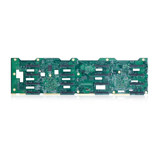
Introduction to the SAS-836A Backplane The SAS-836A backplane has been designed to utilize the most up-to-date technol- ogy available, providing your system with reliable, high-quality performance. -
Page 9: Chapter 2 Jumper Settings And Pin Definitions
Chapter 2: Jumper Settings and Pin Definitions Chapter 2 Jumper Settings and Pin Definitions Front Connectors and Jumpers Figure 2-1. Front Connectors Front Connectors 1. Activity LED Header ACT_IN#0- 7. I C Connector#3 JP52 7: JP26 8. I C Connector#4 JP96 2. -
Page 10: Front Connector And Pin Definitions
SAS-836A Backplane User's Guide Front Connector and Pin Definitions #1 - #2. Activity LED Header SAS Activity LED Header Pin Definitions (JP26) The activity LED headers, designated JP26 Pin # Definition Pin # Definition and JP47, are used to indicate the activity... - Page 11 Chapter 2: Jumper Settings and Pin Definitions #5., #6., #7., #8. I C Connectors C Y-Cable Connector The I C connectors, designated JP37, JP52, Pin Definitions (JP37, JP52, JP95, JP95, and JP96, are for enclosure manage- and JP96) ment of the I C mode connection.
-
Page 12: Front Jumper Locations And Pin Definitions
SAS-836A Backplane User's Guide Front Jumper Locations and Pin Definitions JP84 JP35 JP50 JP100 JP99 JP61 JP62 JP63 JP98 JP97 JP64 Figure 2-2. Front Jumpers Explanation of Jumpers Connector Pins To modify the operation of the backplane, jumpers can be used to choose between optional settings. -
Page 13: Fan Jumper Settings
Chapter 2: Jumper Settings and Pin Definitions Fan Jumper Settings The SAS-836A backplane can use up to four fans. To utilize each fan, both jumpers must be configured as instructed below. Fan Jumper Settings Jumper Jumper Settings Note Closed: With fan (default) -
Page 14: Front Led Indicators
SAS-836A Backplane User's Guide Front LED Indicators POWER LEDS FAN FAILURE LEDS ALARM LEDS Figure 2-3. Front LEDs Front LEDs State Specification Fan #1 Fail Failure in Fan #1 Fan #2 Fail Failure in Fan #2 Fan #3 Fail Failure in Fan #3... -
Page 15: Rear Connectors And Led Indicators
Chapter 2: Jumper Settings and Pin Definitions Rear Connectors and LED Indicators SAS #11 SAS #15 SAS #7 SAS #3 R158 R345 R105 R395 R346 R190 R301 R141 R347 R456 R102 R108 R310 SAS #10 SAS #6 SAS #14 SAS #2 R385 Q44 Q43 R157... - Page 16 SAS-836A Backplane User's Guide Disclaimer (cont.) The products sold by Supermicro are not intended for and will not be used in life sup- port systems, medical equipment, nuclear facilities or systems, aircraft, aircraft devices, aircraft/emergency communication devices or other critical systems whose failure to per- form be reasonably expected to result in significant injury or loss of life or catastrophic property damage.
Need help?
Do you have a question about the SAS-836A and is the answer not in the manual?
Questions and answers