Table of Contents
Advertisement
Quick Links
Manufactured under license from Dolby Laboratories Licens-
ing Corporation.
DOLBY, the double-D symbol
and "PRO LOGIC" are
trademarks of Dolby Laboratories Licensing Corporation.
SAFETY PRECAUTION FOR SERVICE MANUAL ........................................................................................................... 2
IMPORTANT SERVICE NOTES (FOR U.K. ONLY) .......................................................................................................... 3
SPECIFICATIONS ............................................................................................................................................................. 4
NAMES OF PARTS ........................................................................................................................................................... 5
WIRING OF PRIMARILY SUPPLY LEADS (FOR U.K. ONLY) .......................................................................................... 7
OPERATION MANUAL ...................................................................................................................................................... 8
DISASSEMBLY ................................................................................................................................................................ 11
REMOVING AND REINSTALLING THE MAIN PARTS ................................................................................................... 14
ADJUSTMENT ................................................................................................................................................................. 15
TEST MODE .................................................................................................................................................................... 18
RDS OPERATION ........................................................................................................................................................... 18
NOTES ON SCHEMATIC DIAGRAM .............................................................................................................................. 22
BLOCK DIAGRAM ........................................................................................................................................................... 23
SCHEMATIC DIAGRAM / WIRING SIDE OF P.W.BOARD .............................................................................................. 26
VOLTAGE ........................................................................................................................................................................ 46
WAVEFORMS OF CD CIRCUIT ...................................................................................................................................... 47
TROUBLESHOOTING (CD SECTION) ........................................................................................................................... 48
FUNCTION TABLE OF IC ................................................................................................................................................ 52
FL DISPLAY ...................................................................................................................................................................... 58
REPLACEMENT PARTS LIST/EXPLODED VIEW
PACKING OF THE SET (FOR U.K. ONLY)
SERVICE MANUAL
CONTENTS
SHARP CORPORATION
CD-DP2500H
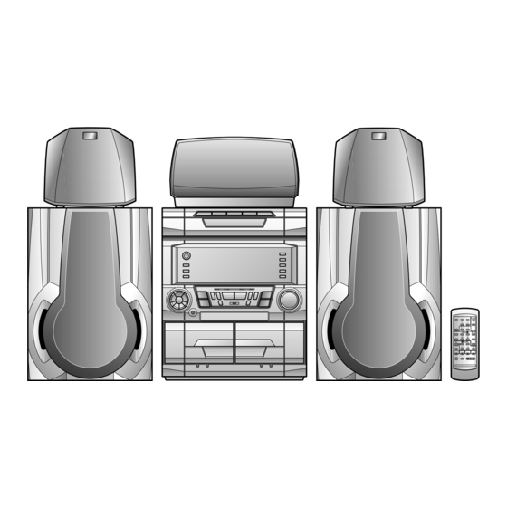
CD-DP2500H Mini Component System consisting of CD-
DP2500H (main unit), CP-DP2500H (front speakers),
GBOXS0038AWM1 (centre speaker) and GBOXS0039AWM1
(surround speakers).
• In the interests of user-safety the set should be restored to its
original condition and only parts identical to those specified be
used.
• Note for users in UK
Recording and playback of any material may require consent which SHARP
is unable to give. Please refer particularly to the provisions of Copyright Act
1956, the Dramatic and Musical Prefomers Protection Act 1956, the
Preformers Protection Acts 1963 and 1972 and to any subsequent statutory
enactments and orders.
This document has been published to be used
for after sales service only.
The contents are subject to change without notice.
CD-DP2500H
No. S4035CDP2500H
Page
Advertisement
Table of Contents

Related Manuals for Sharp CD-DP2500H


Summary of Contents for Sharp CD-DP2500H
-
Page 1: Table Of Contents
• Note for users in UK Recording and playback of any material may require consent which SHARP is unable to give. Please refer particularly to the provisions of Copyright Act 1956, the Dramatic and Musical Prefomers Protection Act 1956, the... -
Page 2: Safety Precaution For Service Manual
CD-DP2500H SAFETY PRECAUTION FOR SERVICE MANUAL (FOR U.K.) Precaution to be taken when replacing and servicing the Laser Pickup. The AEL (Accessible Emission Level) of Laser Power Output for this model is specified to be lower than Class I Requirements. -
Page 3: Important Service Notes (For U.k. Only)
CD-DP2500H (FOR AUSTRALIA/NEW ZEALAND) CAUTION Laser Diode Properties Material: GaAIAs Wavelength: 780 nm Emission Duration: continuous Laser Output: max. 0.6 mW This Mini Component System is classified as a CLASS 1 LASER product. The CLASS 1 LASER PRODUCT label is located on the rear cover. -
Page 4: Specifications
CD-DP2500H FOR A COMPLETE DESCRIPTION OF THE OPERATION OF THIS UNIT, PLEASE REFER TO THE OPERATION MANUAL. SPECIFICATIONS Output terminals: Front speakers; 6 ohms General Centre speaker; 6 ohms Power source: AC 230-240 V, 50 Hz Surround speakers; 12 ohms Power consumption: 155 W Headphones;... -
Page 5: Names Of Parts
CD-DP2500H NAMES OF PARTS Front panel 1. (CD) Disc Tray 2. (CD) Disc Skip Button 3. (CD) Disc Number Select Buttons 4. (CD) Open/Close Button 5. Extra Bass Indicator 6. Spectrum Analyzer/Volume Level Indicator 7. (CD) Disc Number Indicators 8. (CD/TUNER) Memory Indicator 9. - Page 6 CD-DP2500H Rear panel 1. AC Power Lead 2. CD Digital Output Socket 3. FM 75 Ohms Aerial Socket 4. AM Loop Aerial Socket 5. Video/Auxiliary (Audio Signal) Input Sockets 6. Front Speaker Terminals 7. Centre Speaker Terminals 8. Surround Speaker Terminals Front speaker 1.
-
Page 7: Wiring Of Primarily Supply Leads (For U.k. Only)
CD-DP2500H Remote control 1. Remote Control Transmitter LED 2. Surround Level Buttons 3. Centre Level Buttons 4. Dolby Pro Logic Surround Mode Button 5. Test Tone Button 6. Balance Control Buttons Tuner control section 7. Preset Up/Down Buttons CD control section 8. -
Page 8: Operation Manual
CD-DP2500H OPERATION MANUAL – 8 –... - Page 9 CD-DP2500H – 9 –...
- Page 10 CD-DP2500H – 10 –...
-
Page 11: Disassembly
CD-DP2500H DISASSEMBLY Note 1: Caution on Disassembly How to open the changer manually. (Fig. 12-1) Follow the below-mentioned notes when disassembling 1. In this state, turn fully the lock lever in the arrow direction the unit and reassembling it, to keep it safe and ensure through the hole on the loading chassis bottom. - Page 12 CD-DP2500H Bracket (K2)x1 Switch PWB LOCK LEVER (H1)x1 (K1)x2 ø3x10mm (K1)x4 ø3x10mm Display PWB (H3)x1 (F3)x1 Volume Move Unit Headphones Figure 12-1 (H2)x4 ø3x12mm Open (L1)x5 Cassette ø3x10mm CLAMP LEVER Holder Bracket (K1)x1 Lug Wire Tape ø3x10mm Mechanism Figure 12-4...
- Page 13 CD-DP2500H (M2) x1 (P1)x1 CD Player CD Servo ø3x8mm Base (P3) x2 Turntable (P2) x2 Disc Tray (P3) x2 (M1) x2 Figure 13-3 (Q2) x3 Mechanism CD Player Unit Loading Figure 13-1 Motor (Q1) x1 (Q1) x1 (N1) x3 (R1) x5...
-
Page 14: Removing And Reinstalling The Main Parts
CD-DP2500H REMOVING AND REINSTALLING THE MAIN PARTS TAPE MECHANISM SECTION TAPE 2 Perform steps 1 to 7 and 11 of the disassembly method to Record/Playback remove the tape mechanism. Head How to remove the record/playback and erase heads (TAPE 2) (See Fig. 14-1) 1. -
Page 15: Adjustment
CD-DP2500H CD MECHANISM SECTION Perform steps 1, 2, 3, and 13 to 15 of the disassembly method to remove the CD mechanism. How to remove the loading motor Loading Motor (See Fig. 15-1) 1. Bend the hooks (A1) x 5 pcs., to remove the loading motor. - Page 16 CD-DP2500H TUNER SECTION fL: Low-range frequency fH: High-renge frequency MAIN PWB • AM IF/RF Signal generator: 400 Hz, 30%, AM modulated Test Stage Frequency Frequency Setting/ Instrument CF301 Display Adjusting Connection Parts IC302 AM IF 450 kHz 1,620 kHz T351 AM Band —...
- Page 17 CD-DP2500H EXPLANATION OF DOLBY SURROUND PRO LOGIC AND EVALUATION METHOD Outline • Namely, two speakers are connected in parallel to one • In the normal mode of Pro Logic ON mode the amplifiers for amplifier. C-ch and S-ch are in operative state, so that the SP output •...
-
Page 18: Test Mode
CD-DP2500H TEST MODE During POWER OFF mode,push below each 2 keys [ON/STAND-BY] key. Then go to each TEST MODE. TEST MODE CONTENTS [ON/STAND-BY] [TUNER] + [X-BASS] TEST 1 TUNER PRESET MEMORY CLEAR [ON/STAND-BY] [MEMORY/SET] + [X-BASS] TEST 2 TUNER PRESET FOR PRODUCTION [ON/STAND-BY] [>>] + [X-BASS]... - Page 19 Can select and stand-by EON—PTY and EON—TI are basically stand-by → receive the desired program of ON station. 2. The difference point from current CD-C75H RDS. (CD-C75H — CD-DP2500H) 1. PTY item: added TA. (TTL 18 kind.) 2. Each “TP”, “TA” ind. light up or go out individually.
- Page 20 CD-DP2500H EON summary notice for reference 1. EON-TI/PTY EON stand-by can be set, only when EON ind. lights up. While EON ind. goes out (NO EON STATION), EON stand-by can't be set. If the EON button is pressed, then “NO EON” is indication the display.
- Page 21 CD-DP2500H – 21 –...
-
Page 22: Notes On Schematic Diagram
CD-DP2500H NOTES ON SCHEMATIC DIAGRAM • The indicated voltage in each section is the one measured • Resistor: by Digital Multimeter between such a section and the chas- To differentiate the units of resistors, such symbol as K and sis with no signal given. -
Page 23: Block Diagram
CD-DP2500H CLAMP DISC OPEN/ CLOSE NUMBER CD DIGITAL OUT UP/DOWN MOTOR IC99 TO MAIN SECTION TO DISPLAY SECTION (TO IC601) 9 10 45 46 47 48 32 31 30 LC78641E SERVO/SIGNAL CONTROL CONT5 SLD0 XOUT SPD0 16.9344MHz VDD5V 5 18 36 44 49 50... - Page 24 CD-DP2500H AM LOOP FM IF FM IF ANTENNA Q301 CF302 CF301 T303 CNP301 LOW PASS AM IF FILTER L341 BALUN L354 T351 CF352 MONO/ST COIL FM IF IN FM+B AM MIX AM IF GND VCC MO/ST T306 IC303 LA1832 FM/AM IF MPX.
- Page 25 CD-DP2500H FL701 DISPLAY 1 2 3 15 16 24 54 55 56 LED711~LED714 Q701 IC702 Q702 BU2092F Q703 Q710 Q711 Q712 Q751 Q753 VOLUME JOG701 M701 MOVE MOTOR TAPE MECHANISM IC703 BU2092F LED701~LED703 IC701 RESET IC704 IX0333AW KIA7042P SYSTEM MICROCOMPUTER...
-
Page 26: Schematic Diagram / Wiring Side Of P.w.board
CD-DP2500H CD SERVO PWB-C Vref TIN1 FIN1 0.047 FIN2 TIN2 LA9235M SERVO AMP. 47/6.3 2.2/50 FIN1 100P ODRV 0.022 FIN2 RFSW 120K 6.8K AGCON TIN1 (CH) 0.01 47/10 TIN2 100/10 REF1 0.01 0.0047 10/35 VREF 0.022 0.33 ODRV RFEV PH/BH... - Page 27 CD-DP2500H CD SIGNAL 100P 0.01 100P 100P 100P 100P 100P 100P DIGITAL OUT PWB-A5 0.022 2.2µH EFMO VDD5V 80 79 78 77 76 75 74 72 71 70 69 68 67 66 65 0.022 0.047 PD01 COMMAND 0.022 GENERAL INTERFACE 1.5M...
- Page 28 CD-DP2500H PLAYBACK SIGNAL R174 RECORD SIGNAL Q110 C153 R113 R114 KRC104 M 100/16 R115 4.7K Q109 Q111 KTA1266 GR KRC104 M TAPE MECHANISM ASS'Y(210) R112 R120 TAPE1 R102 PLAYBACK HEAD C116 C120 C102 R-CH 47/25 560P TAPE1_R 0.001 A_GND TAPE1_L...
- Page 29 CD-DP2500H TAPE_R CHASSIS T1/T2 REC_PLAY REC_R R182 100K R181 REC_L 100K Q121 Q122 KTC3199 GR KTC3199 GR TAPE_L R132 BIAS 5.6K R154 R153 D102 DS1SS133 D_GND R120 A_10V D101 C120 C122 DS1SS133 560P A_GND 47/25 R126 M_GND 5.6K R122 100K...
- Page 30 CD-DP2500H TO TUNE FM SIGNAL CD SIGNAL VIDEO SIGNAL PLAYBACK SIGNAL R507 RECORD SIGNAL R511 150K 150K C542 0.01 C523 0.68 R506 R508 150K C520 1/50 64 63 62 61 60 59 58 57 56 55 54 53 52 51 50 49 48 47 46 45 44 43...
- Page 31 CD-DP2500H P34 2-E CNP701 TO DISPLAY PWB FC701 TO DECK SECTION TO TUNER SECTION P29 12-B P33 10-H 11 12 13 14 15 16 17 18 19 20 21 CNP602 TAPE_R R421 IC601 KIA4558P OPA AMP. C422 1/50 C601 R406...
- Page 32 CD-DP2500H C302 0.001 CHASSIS AM ANT. T303 C331 C330 0.047 15P(UJ) C323 0.022 C332 C338 0.022 CHASSIS 0.001 AM TRACKING fL D301 C342 DS1SS133 AM LOOP 0.022 ANTENN AM BAND D302 R350 VD301 L341 DS1SS133 2.7K COVERAGE fL C335 SVC348S...
- Page 33 CD-DP2500H TP302 C373 0.018 R350 2.7K C371 R361 1/50 1.2K L354 LOW PASS C367 FILTER 1/50 R362 C372 1.2K 1/50 2 0 1 9 1 8 1 5 1 4 LT21 2.2µH IC303 LA1832S RT32 RT33 FM IF DET/FM MPX/AM IF...
- Page 34 CD-DP2500H FL701 BJ744GNK FL DISPLAY R701 R703 100K 100K R702 100K R706 C702 47/50 Q703 VLOAD R707 KTC3199 GR RM710 RM712 RM711 100K 100K 100K CNS702 M _10V SW_5V RM714 IC701 VLOAD DIST0/P15 P36 1 - G Q712 CNP804 DIST1/P16...
- Page 35 CD-DP2500H CNP12 CD SERVO PWB P27 12-F CNS701 BI701 DISPLAY PWB-A2 C723 RS757 47/25 C724 0.022 DATA CLOCK RS730 RS708 RS701 M– LCK_0 C720 LED711 47/50 LED712 RS731 RS709 RS702 C721 LED713 RS703 0.022 R774 LED714 RS732 RS710 RS704 SLI325YCx4...
- Page 36 CD-DP2500H FM SIGNAL IC902 IC901 STK40203 STK40271 Front_R Center POWER AMP. Front_L Rear POWER AMP. Ch 1 Ch 2 Ch 1 Ch 2 C911 2 3 4 5 6 7 10 11 2 3 4 R988 R906 5 6 7...
- Page 37 CD-DP2500H HEADPHONES PWB-A4 L601 100µH Rear Ch 2 C698 0.022 R971 CNS806 4.7(1/2) CNP806 C943 C960 10 11 220P 47/50 R941 D909 R973 R946 M901 C941 (1/4) DS1SS133 FAN MOTOR 100/50 Q910 R948 R947 KTC3203 Y R972 C961 R942 R974 10/50 0.1(1W)
- Page 38 CD-DP2500H RDS PWB-G MAIN PWB-A1 CT28 CT29 CT27 24 23 22 21 20 19 18 17 16 15 14 13 D304 D303 C348 CHASSIS C302 ICT21 XT21 R349 R378 R374 R372 1 2 3 4 5 6 7 8 9 10 11 12...
- Page 39 CD-DP2500H P41 12 - D CNP701 TO DISPLAY PWB FC701 P44 4 - A TO CD PWB CNP11 C603 CNS401 R604 5 6 7 8 IC601 R608 D602 R607 R603 D603 D601 R220 C606 R421 R605 R610 R601 C616 C395...
- Page 40 CD-DP2500H SW732 OPEN/CLOSE P44 5 - A TO CD SERVO PWB CNP12 CNS701 COLOR TABLE BROWN RD(R) ORANGE YELLOW BI701 GREEN C720 BLUE CNS701A SW723 Q703 VIOLET R703 PTY TI SERCH GRAY Q702 RD21 R702 WH(W) WHITE Q701 SW724 BLACK...
- Page 41 CD-DP2500H SW732 SW730 SW729 SW731 SW728 OPEN/CLOSE DISC 3 DISC 2 DISC SKIP DISC 1 RD29 RD25 RD27 RD26 RD28 SWITCH PWB-A3 C701 FL701 D704 D701 SW720 R726 R711 STAND-BY CNP701 R794 SW721 C713 IC701 R790 CLOCK Q709 RD19 XL701...
- Page 42 CD-DP2500H P39 10 - D TO MAIN PWB CNP501 CNP805 R971 RL901 R955 R954 C802 C801 D909 C936 R973 Q910 C961 C914 C937 C903 C917 R940 R922 C915 R902 R937 C945 R903 C949 R933 C933 R921 C910 C931 R901 R939...
- Page 43 CD-DP2500H CHASSIS CNP601 R985 C984 C985 SO901 C698 R986 SPEAKER TERMINAL R981 C974 – C699 REAR L904 L-CH RL902 R982 – REAR R-CH R983 L903 JK601 – C979 C978 HEADPHONES CENTER L902 Q911 C987 – FRONT L-CH Q909 HEADPHONES –...
- Page 44 CD-DP2500H P39 9 - A P40 4 - B TO MAIN PWB TO DISPLAY PWB CNS401 CNS701 CD SERVO PWB-C 9 10 CNP12 CNP11 CNP5 E C B ZD61 B C E CNP1 40 41 1 2 3 CNP3 CNP4...
- Page 45 CD-DP2500H P40 5 - G TAPE MECHANISM TO DISPLAY PWB ASSEMBLY(210) CNP702 FC702 TAPE MECHANISM PWB-E SOLM SOLM SOLENOIDE SOLENOIDE TAPE MOTOR TAPE 2 TAPE 1 ERASE HEAD RECORD/PLAYBACK PLAYBACK HEAD HEAD CNS101 CNS102 1 2 3 4 5 6 7...
-
Page 46: Voltage
CD-DP2500H VOLTAGE IC701 IC902 IC501 IC101 IC303 PIN VOLTAGE NO. VOLTAGE NO. VOLTAGE NO. VOLTAGE NO. VOLTAGE VOLTAGE NO. VOLTAGE NO. VOLTAGE 1.6V 0.7V 0V (0V) 2.1V (2.1V) 4.6V 4.9V 4.9V 1.6V 0V (0V) 4.5V (4.5V) 4.6V 4.9V 1.6V 4.6V 3.9V... -
Page 47: Waveforms Of Cd Circuit
CD-DP2500H WAVEFORMS OF CD CIRCUIT Stopped Stopped 1999/04/05 17:33:17 CH1=500mV CH3=500mV 500ms/div CH1=500mV CH3=1V CH4=1V 500ms/div DC 10:1 DC 10:1 (500ms/div) DC 10:1 DC 10:1 DC 10:1 (500ms/div) NORM:20kS/s NORM:20kS/s PDO1 IC2 1 IC2 24 PDO2 IC2 2 IC2 23... -
Page 48: Troubleshooting (Cd Section)
CD-DP2500H TROUBLE SHOOTING When the CD does not function When the CD section does not operate when the objective lens of the optical pickup is dirty, this section may not operate. Clean the objective lens, and check the playback operation. When this section does not operate even after the above step is taken, check the following items. - Page 49 CD-DP2500H (1) Focus-HF system check Stopped CH1=500mV CH3=500mV 500ms/div Although a CD is inserted and the cover is closed, "NO DC 10:1 DC 10:1 (500ms/div) NORM:20kS/s DISC" is displayed. Press the OPEN/CLOSE switch (SW1) without inserting a disc, and try starting the playback operation.
- Page 50 CD-DP2500H (2) Tracking system check Check the TE waveform at pin 18 on IC1. The tracking servo is not activated. If the waveform shown in Figure 50-1 appears and soon after Check the peripheral circuits at pins 18 and 19 on IC1, pin 23 on NO DISC appears.
- Page 51 CD-DP2500H (4) PLL system check Stopped 1999/04/05 17:33:17 CH1=500mV CH3=1V CH4=1V 500ms/div (500ms/div) DC 10:1 DC 10:1 DC 10:1 NORM:20kS/s When a disc is loaded, start play operation. PDO1 The HF waveform is normal, but the TOC data cannot be PDO2 read.
-
Page 52: Function Table Of Ic
CD-DP2500H FUNCTION TABLE OF IC IC1 VHiLA9235M/-1: Servo Amp. (LA9235M) ODRV FIN1 LA9235M RFSW FIN2 AGCON 28 RF- FIN3 FIN4 26 N/C 25 PH 24 BH REF1 ODRV 23 N/C PH/BH 22 RFEV VREF 21 FE- 20 FE LDOF 19 TE-... - Page 53 CD-DP2500H IC2 VHiLC78641E-1: Servo/Signal Control (LC78641E) (1/2) Terminal Name Input/Output Setting in Reset Function Pin No. PDO1 Output – For PULL Phase-comparison output terminal for built-in VOC control. PDO2 Output – Phase-comparison output terminal for built-in VOC control. Rough servo : OFF, phase servo : ON.
- Page 54 CD-DP2500H IC2 VHiLC78641E-1: Servo/Signal Control (LC78641E) (2/2) Terminal Name Input/Output Setting in Reset Function Pin No. LVDD – – L channel Power terminal for L channel. LCHO Output 1/2VDD D/A converter L channel output terminal. LVSS – – Ground terminal for L channel. Surely connected to 0V.
- Page 55 CD-DP2500H IC701 RH-iX0333AWZZ: System Microcomputer (IX0333AW) (1/2) Pin No. Port Name Terminal Name Input/Output Function — (+) POWER SUPPLY -20dBATT Output -20dB ATTENUATOR S-BUSY Output Not used LCK1 Output LED DRIVER LCK (BU2092-2) LCK0 Output LED DRIVER LCK (BU2092-1) DP REQ...
- Page 56 CD-DP2500H IC701 RH-iX0333AWZZ: System Microcomputer (IX0333AW) (2/2) Pin No. Port Name Terminal Name Input/Output Function P120 PLAY SW_B Input PLAY SWITCH FOR T2 P119 Input TAPE2 A-SIDE FULL PROOF P118 Input TAPE2 B-SIDE FULL PROOF P117 MIC SW Input MIC SWITCH...
- Page 57 CD-DP2500H IC401 VHiLC75341/-1: Audio Processor (LC75341) ROUT LOUT LBASS RBASS 0.1uF 0.1uF LTRE RTRE LSEL0 RSEL0 R1 R2 24 23 22 21 20 19 18 17 16 15 14 13 LC75341 10 11 12 Figure 57 BLOCK DIAGRAM OF IC...
-
Page 58: Fl Display
CD-DP2500H FL701 VVKBJ744GNK-1: FL Display (1G~8G) PIN CONNECTION PIN NO. 20 19 18 17 16 15 14 13 12 11 10 CONNECTION 9G 8G 7G 6G 5G 4G 3G 2G NP NP F1 F1 F1 30 29 28 27 26 25 24 23 22 21 PIN NO. - Page 59 CD-DP2500H PARTS GUIDE CD-DP2500H MODEL CD-DP2500H Mini Component System consisting of CD- DP2500H (main unit), CP-DP2500H (front speakers), GBOXS0038AWM1 (centre speaker) and GBOXS0039AWM1 (surround speakers). “HOW TO ORDER REPLACEMENT PARTS” To have your order filled promptly and correctly, please furnish the For U.S.A.
- Page 60 VHIKIA7810AP1 AF Voltage Regulator,KIA7810AP PT801 RTRNP0298AWZZ J BH Power (Main)with connector (NS801,802,803) IC804 VHIAN78L05/-1 AE Constant Voltage Regulator, PT802 RTRNP0313AWZZ J AN Power (Sub) [CD-DP2500H] AN78L05 IC901 VHISTK40271-1 AZ Power Amp,STK40271 T303 RCILA0052AWZZ AE AM Antenna T306 RCILB0058AWZZ AC OSC,AM...
- Page 61 CD-DP2500H PRICE PRICE DESCRIPTION PARTS CODE PARTS CODE DESCRIPTION RANK RANK AB 100 µF,6.3V,Electrolytic AB 1 µF,50V,Electrolytic VCEAZA0JW107M J C370~372 VCEAEA1HW105M J AA 0.018 µF,16V VCCCTV1HH680J AA 68 pF,50V C373,374 VCTYPA1CX183K AA 0.0015 µF,50V AA 0.001 µF,50V VCKYTV1HB152K C375 VCKYBT1HB102K AB 0.022 µF,25V...
- Page 62 DESCRIPTION PARTS CODE RANK RANK AA 0.022 µF,25V AB 10 µF,50V,Electrolytic C610~612 VCTYMN1EF223Z C961 VCEAZA1HW106M J 0.0027 µF,16V AA 0.022 µF,50V [CD-DP2500H] C613~616 VCTYMN1CX272Z J C962~969 VCKZPA1HF223Z AB 2.2 µF,50V,Electrolytic AA 0.001 µF,50V C617,618 VCEAEA1HW225M J C970,971 VCKYPA1HB102K AB 47 µF,25V,Electrolytic AA 0.022 µF,50V...
- Page 63 CD-DP2500H PRICE PRICE DESCRIPTION PARTS CODE PARTS CODE DESCRIPTION RANK RANK R137,138 VRD-MN2BD682J AA 6.8 kohms,1/8W R512 VRD-MN2BD334J AA 330 kohms,1/8W R139,140 VRD-MN2BD152J AA 1.5 kohms,1/8W R513 VRD-ST2CD331J AA 330 ohms,1/6W R141,142 VRD-MN2BD101J AA 100 ohm,1/8W R516 VRD-MN2BD222J AA 2.2 kohms,1/8W...
- Page 64 CD-DP2500H PRICE PRICE DESCRIPTION PARTS CODE DESCRIPTION PARTS CODE RANK RANK R788 VRD-MN2BD472J AA 4.7 kohms,1/8W RD10 VRD-MN2BD153J AA 15 kohms,1/8W R790 VRD-MN2BD473J AA 47 kohms,1/8W RD11 VRD-MN2BD333J AA 33 kohms,1/8W R793 VRD-MN2BD104J AA 100 kohm,1/8W RD12 VRD-MN2BD104J AA 100 kohm,1/8W...
- Page 65 CD-DP2500H PRICE PRICE DESCRIPTION PARTS CODE PARTS CODE DESCRIPTION RANK RANK CNP804 92LCONE9P53253 J AC Plug,9Pin 92LHPC1LXASY BD Pickup Unit Ass’y CNP805 QCNCW010NAWZZ J Socket,13Pin 306- 1 ———— — Pickup Unit CNP806 92LCONE2P53253 J AB Plug,2Pin (Not Replacement Item) CNS1A/B QCNWN1537AWZZ J AG Connector Ass’y,7/7Pin...
- Page 66 CD-DP2500H PRICE PRICE PARTS CODE DESCRIPTION PARTS CODE DESCRIPTION RANK RANK LHLDZ1257AWZZ Holder,Volume Move 92LP5876-1 AC Label,Specification MLOKC0003AWZZ J AD Lock Lever,Casette,Tape1 92LJ9774A AC Cushion,Foot MLOKC0004AWZZ J AD Lock Lever,Casette,Tape2 92LJ9777P AD Port Cushion MSPRD0109AWFJ J AB Spring,Casette Lock Lever,...
- Page 67 CD-DP2500H PRICE PRICE PARTS CODE DESCRIPTION PARTS CODE DESCRIPTION RANK RANK P.W.B. ASSEMBLY (Not Replacement Item) PWB-A1~5 92LPWB3308MANS J — Main/Display/Switch/Head- phones/Digital Output (Combined Ass’y) PWB-B 92LPWB3308PWRS J — Power Supply PWB-C 92LPWB3306CDUS J — CD Servo PWB-D QPWBF0027AWZZ J...
- Page 68 CD-DP2500H 306-2 306-1 306-3 703x2 305x2 PWB-D Figure 9 CD MECHANISM EXPLODED VIEW – 8 – – 9 –...
- Page 69 CD-DP2500H PWB-A2 605x5 It is contained FL701 in the volume PWB-H1 Washer 605x2 PWB-A3 M701 PWB-A4 PWB-H2 615x2 604x2 201-6 201-19 201-1 201-23 201-11 201-16 201-17 201-24 604x2 201-5 201-7 201-22 201-20 201-12 201-18 201-4 201-21 201-15 605x5 201-8 CNS100...
- Page 70 CD-DP2500H 608x14 202-1 PWB-A5 202-2 PWB-B 608x4 608x2 PWB-G 256x2 (K801,K802) Silicon Grease IC901 248x10 614x2 Silicon CNS100 609x4 Grease IC802 IC902 Silicon Grease 604x4 Q823 IC801 609x3 614x2 M901 613x4 237 254 PT801 PWB-A1 601x2 203-1 203-2 608x2 Figure 11 CABINET EXPLODED VIEW (2/3) –...
- Page 71 CD-DP2500H 604x2 604x2 MECHANISM PWB-F 272x4 261x3 204-1 204-2 PWB-C Figure 12 CABINET EXPLODED VIEW (3/3) – 12 – – 11 –...
- Page 72 CD-DP2500H FRONT SPEAKER SUPER TWEETER TWEETER SP3(L-CH) SP1(L-CH) SP4(R-CH) SP2(R-CH) C1,2 Capacitor WOOFER SP5(L-CH) SP6(R-CH) 912x2 (with Capacitor C1,2) 912x4 909x2 SP1,2 914x2 SP5,6 SP3,4 914x2 913x4 SUPER 909x2 TWEETER SP1(L-CH) SP2(R-CH) TWEETER C1,2 SP3(L-CH) Capacitor 2.2 µF,100V, SP4(R-CH) Electrolytic (N.P.)
- Page 73 CD-DP2500H 904x4 CENTER SPEAKER 904x4 906x4 904x6 SURROUND SPEAKER SP1,2 SP1,2 Figure 14 SPEAKER EXPLODED VIEW (2/2) – 13 – – 14 –...
- Page 74 REAR SIDE OF MAIN SET REAR SIDE OF FRONT SPEAKER © COPYRIGHT 2000 BY SHARP CORPORATION ALL RIGHTS RESERVED. SHARP CORPORATION Communication Systems Group Quality & Reliability Control Center No part of this publication may be reproduced, Higashihiroshima, Hiroshima 739-0192, Japan...
Need help?
Do you have a question about the CD-DP2500H and is the answer not in the manual?
Questions and answers