Table of Contents
Advertisement
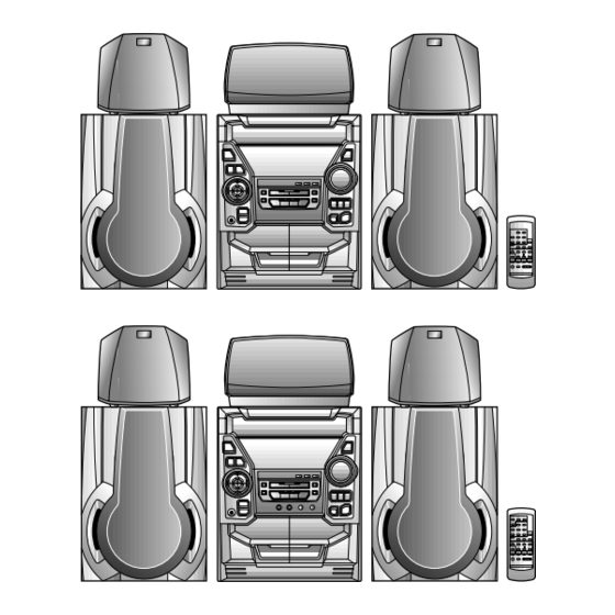
CD-DP2500W
CD-DK2500W
Manufactured under license from Dolby Laboratories Licens-
ing Corporation.
DOLBY, the double-D symbol
and "PRO LOGIC" are
trademarks of Dolby Laboratories Licensing Corporation.
Safety Precaution For Service Manual ........................................................................................................... 2
Voltage Selection ..................................................................................................................................................... 2
Specifications ............................................................................................................................................................. 3
Names Of Parts ........................................................................................................................................................... 4
Operation Manual ...................................................................................................................................................... 8
Disassembly .................................................................................................................................................................. 9
Removing And Reinstalling The Main Parts ................................................................................................... 12
Test Mode .................................................................................................................................................................... 13
Adjustment ................................................................................................................................................................. 14
Notes On Schematic Diagram .............................................................................................................................. 16
Block Diagram ........................................................................................................................................................... 17
Schematic Diagram / Wiring Side Of P.w.board .............................................................................................. 20
Voltage ........................................................................................................................................................................ 42
Waveforms Of Cd Circuit ...................................................................................................................................... 43
Troubleshooting (Cd Section) ........................................................................................................................... 44
Function Table Of Ic ................................................................................................................................................ 48
FL DISPLAY ...................................................................................................................................................................... 54
REPLACEMENT PARTS LIST/EXPLODED VIEW
SERVICE MANUAL
CONTENTS
SHARP CORPORATION
CD-DP2500W/DK2500W
CD-DP2500W
CD-DP2500W Mini Component System consisting of CD-
DP2500W (main unit), CP-DP2500 (front speakers),
GBOXS0038AWM1 (centre speaker) and GBOXS0039AWM1
(surround speakers).
CD-DK2500W
CD-DK2500W Mini Component System consisting of CD-
DK2500W (main unit), CP-DP2500 (front speakers),
GBOXS0038AWM1 (centre speaker) and GBOXS0039AWM1
(surround speakers).
DIFFERENCE BETWEEN CD-DP2500W AND CD-DK2500W
SECTION
CD-DP2500W
KARAOKE
Non
• In the interests of user-safety the set should be restored to its
original condition and only parts identical to those specified be
used.
This document has been published to be used
for after sales service only.
The contents are subject to change without notice.
No. S4034CDDP2500
CD-DK2500W
Used
Page
Advertisement
Table of Contents

Related Manuals for Sharp CD-DP2500W


Summary of Contents for Sharp CD-DP2500W
-
Page 1: Sharp Corporation
CD-DP2500W/DK2500W SERVICE MANUAL No. S4034CDDP2500 CD-DP2500W CD-DP2500W Mini Component System consisting of CD- DP2500W (main unit), CP-DP2500 (front speakers), GBOXS0038AWM1 (centre speaker) and GBOXS0039AWM1 (surround speakers). CD-DP2500W CD-DK2500W CD-DK2500W Mini Component System consisting of CD- DK2500W (main unit), CP-DP2500 (front speakers), GBOXS0038AWM1 (centre speaker) and GBOXS0039AWM1 (surround speakers). -
Page 2: Safety Precaution For Service Manual
CD-DP2500W/DK2500W SAFETY PRECAUTION FOR CAUTION SERVICE MANUAL Precaution to be taken when replacing and servicing the Laser Pickup. The AEL (Accessible Emission Level) of Laser Power Output This Mini Component System is classified as a CLASS 1 for this model is specified to be lower than Class I Requirements. -
Page 3: Specifications
CD-DP2500W/DK2500W FOR A COMPLETE DESCRIPTION OF THE OPERATION OF THIS UNIT, PLEASE REFER TO THE OPERATION MANUAL. SPECIFICATIONS General Tuner section Power source: AC 110/127/220/230-240 V, 50/60 Hz Frequency range: FM; 88-108 MHz Power consumption: 155 W AM; 531-1,602 kHz Dimensions: Width;... -
Page 4: Names Of Parts
CD-DP2500W/DK2500W NAMES OF PARTS Front panel [CD-DP2500W] 1. (CD) Disc Tray 2. Extra Bass Indicator 3. Spectrum Analyzer/Volume Level Indicator 4. (CD) Disc Number Indicators 5. (CD/TUNER) Memory Indicator 6. (CD) Pause Indicator 7. (TAPE 2) Record Indicator 8. (CD) Play Indicator 9. - Page 5 CD-DP2500W/DK2500W Front panel [CD-DK2500W] 1. (CD) Disc Tray 2. Extra Bass Indicator 3. Spectrum Analyzer/Volume Level Indicator 4. (CD) Disc Number Indicators 5. Karaoke Maker Indicator 6. (CD/TUNER) Memory Indicator 7. (CD) Pause Indicator 8. (TAPE 2) Record Indicator 9. (CD) Play Indicator...
- Page 6 CD-DP2500W/DK2500W Rear panel 1. AC Voltage Selector 2. AC Power Lead 3. CD Digital Output Socket 4. FM 75 Ohms Aerial Terminal 5. FM Aerial Earth Terminal 6. AM Loop Aerial Input Socket 7. Span Selector Switch 8. Video/Auxiliary (Audio Signal) Input Sockets 9.
- Page 7 CD-DP2500W/DK2500W Remote control [CD-DP2500W] 1. Remote Control Transmitter LED 2. Dolby Pro Logic Surround Mode Button 3. Test Tone Button 4. Centre Level Buttons 5. Surround Level Buttons 6. Balance Control Buttons 7. (CD) Disc Skip Button 8. (CD) Clear Button 9.
-
Page 8: Operation Manual
CD-DP2500W/DK2500W OPERATION MANUAL – 8 –... -
Page 9: Disassembly
CD-DP2500W/DK2500W DISASSEMBLY Note 1: Caution on Disassembly How to open the changer manually. (Fig. 10-1) Follow the below-mentioned notes when disassembling 1. In this state, turn fully the lock lever in the arrow direction the unit and reassembling it, to keep it safe and ensure through the hole on the loading chassis bottom. - Page 10 CD-DP2500W/DK2500W LOCK LEVER (J2)x1 Display PWB (J1)x14 (F3)x1 ø3x10mm Tape Mechanism Headphones (K1)x5 ø3x10mm Open Figure 10-1 Karaoke Cassette Holder (J1)x1 CLAMP LEVER ø3x10mm (H1)x1 ø3x10mm CD-DK2500W ONLY Figure 10-4 (L2) x1 Turntable CAM GEAR RIB Figure 10-2 Disc Tray...
- Page 11 CD-DP2500W/DK2500W (P2) x3 (N1)x1 CD Player CD Servo Mechanism ø3x8mm Base (N3) x2 (N2) x2 Loading Motor (P1) x1 (P1) x1 (N3) x2 (Q1) x5 Figure 11-1 Figure 11-2 CP-DP2500 STEP REMOVAL PROCEDURE FIGURE Front Panel 1. Front Panel .... (A1) x1...
-
Page 12: Removing And Reinstalling The Main Parts
CD-DP2500W/DK2500W REMOVING AND REINSTALLING THE MAIN PARTS TAPE MECHANISM SECTION TAPE 2 Perform steps 1 to 7 and 10 of the disassembly method to Record/Playback remove the tape mechanism. Head How to remove the record/playback and erase heads (TAPE 2) (See Fig. 12-1) 1. -
Page 13: Cd Mechanism Section
CD-DP2500W/DK2500W CD MECHANISM SECTION Perform steps 1, 2, 3, and 11 to 14 of the disassembly method to remove the CD mechanism. How to remove the loading motor Loading Motor (See Fig. 13-1) 1. Bend the hooks (A1) x 5 pcs., to remove the loading motor. -
Page 14: Adjustment
CD-DP2500W/DK2500W ADJUSTMENT • Tape Speed MECHANISM SECTION • Driving Force Check Adjusting Specified Instrument Test Tape Value Connection Point Torque Meter Specified Value 3,000 ± Normal MTT-111 Variable Speaker Play: TW-2111 Tape 1: Over 80 g speed Resistor in 30 Hz... - Page 15 CD-DP2500W/DK2500W EXPLANATION OF DOLBY SURROUND PRO LOGIC AND EVALUATION METHOD Outline • Namely, two speakers are connected in parallel to one • In the normal mode of Pro Logic ON mode the amplifiers for C-ch and S-ch are in operative state, so that the SP output amplifier.
-
Page 16: Notes On Schematic Diagram
CD-DP2500W/DK2500W NOTES ON SCHEMATIC DIAGRAM • The indicated voltage in each section is the one measured • Resistor: by Digital Multimeter between such a section and the chas- To differentiate the units of resistors, such symbol as K and sis with no signal given. -
Page 17: Block Diagram
CD-DP2500W/DK2500W OPEN/ CLAMP DISC CLOSE NUMBER CD DIGITAL OUT UP/DOWN MOTOR IC99 TO MAIN SECTION TO DISPLAY SECTION (TO IC601) 9 10 45 46 47 48 32 31 30 LC78641E SERVO/SIGNAL CONTROL CONT5 SLD0 XOUT SPD0 16.9344MHz VDD5V 5 18 36 44 49 50... - Page 18 CD-DP2500W/DK2500W IC301 FM FRONT END SO301 FM ANTENNA FM IF FM IF BF301 CF303 FM 75Ω T302 FM B.P.F. AM IF Q302 T351 CF352 MONO/ST FM IF IN FM RF FM OSC OSC BUFFER FM+B L312 T301 AM MIX AM IF...
- Page 19 CD-DP2500W/DK2500W FL701 DISPLAY 1 2 3 15 16 24 54 55 56 LED711~LED717 Q701 IC702 Q702 BU2092F Q703 Q710 Q711 Q712 VOLUME VR701 TAPE MECHANISM IC703 BU2092F LED701~LED710 LED718 IC701 RESET IC704 IX0334AW KIA7042P SYSTEM MICROCOMPUTER LATCH AVDD MIC IN...
- Page 20 CD-DP2500W/DK2500W CD SERVO PWB-C Vref TIN1 FIN1 0.047 FIN2 TIN2 1.5M LA9235M SERVO AMP. 47/6.3 2.2/50 FIN1 100P ODRV 0.022 FIN2 RFSW 120K 6.8K AGCON TIN1 (CH) 0.01 47/10 TIN2 100/10 REF1 0.01 0.0047 10/35 VREF 0.022 0.33 ODRV RFEV...
-
Page 21: Figure
CD-DP2500W/DK2500W CD SIGNAL 100P 0.01 100P 100P 100P 100P 100P 100P DIGITAL OUT PWB-A5 2.2µH 0.022 EFMO VDD5V 80 79 78 77 76 75 74 72 71 70 69 68 67 66 65 0.022 0.047 PD01 COMMAND 0.022 GENERAL INTERFACE 1.5M... - Page 22 CD-DP2500W/DK2500W MIC SIGNAL PLAYBACK SIGNAL R174 RECORD SIGNAL Q110 C109 C153 KRC104 M 0.047 100/16 R113 R115 4.7K Q109 Q111 KTA1266 GR KRC104 M TAPE MECHANISM ASS'Y(210) R112 R120 TAPE1 R102 PLAYBACK HEAD C116 47/25 CNP101 C102 R-CH TAPE1_R 0.001...
- Page 23 CD-DP2500W/DK2500W TAPE_R R174 T1/T2 REC_MUTE R182 REC_R 100K R181 REC_L 100K Q121 Q122 KTC3199 GR KTC3199 GR TAPE_L BIAS R154 R153 D102 1SS133 D_GND A_10V C116 D101 47/25 1SS133 A_GND R126 C118 C120 C122 M_GND 5.6K 0.033 560P 47/25 R124 3.9K...
- Page 24 CD-DP2500W/DK2500W CD-DK2500W TO TUNER CNSK1 ONLY P32 5-A P27 1 TO KARAOKE PWB 10 11 CNP401 MIC IN KARAOKE LATCH R507 R511 150K 150K C542 0.01 C523 0.68 R506 R508 150K C520 1/50 R503 64 63 62 61 60 59 58 57 56 55 54 53 52 51 50 49 48 47 46 45 44 43...
- Page 25 CD-DP2500W/DK2500W FC701 CNP701 P28 1-E CD-DP2500W:23Pin TO DISPLAY PWB CD-DK2500W:25Pin TO DECK SECTION TO TUNER SECTION CNP602 SPAN P23 12-B P27 11-H SELECTOR SW799 23 24 25 11 12 13 14 15 16 17 18 19 20 21 100/10 50/9...
- Page 26 CD-DP2500W/DK2500W AM ANT. T303 C331 0.047 C330 C323 0.022 (UJ) C338 0.001 C332 0.022 D301 1SS133 AM TRACKING fL CHASSIS C342 R365 D302 1SS133 0.022 VD301 AM BAND AM LOOP SVC348S COVERAGE fL C335 ANTENNA R358 BF301 560P(SL) T306 3.9K B.P.F.
- Page 27 CD-DP2500W/DK2500W MAIN PWB-A1(3/3) TP302 R364 C373 R363 R365 3.9K 0.015 3.9K C371 R358 R361 1/50 3.9K R350 2.7K R362 C372 C367 1/50 1/50 20 19 18 15 14 13 IC303 LA1832 FM IF DET/FM MPX/AM IF C358 1/50 R352 R353...
- Page 28 CD-DP2500W/DK2500W FL701 BJ744GNK R701 R703 100K 100K R702 100K R706 C702 47/50 Q703 VLOAD KTC3199 GR R707 RM710 RM712 RM711 100K 100K 100K CNS702 BI702 M _10V SW_5V RM714 IC701 VLOAD DIST0/P15 P30 1 - G Q712 DIST1/P16 CNP804 IX0334AW...
- Page 29 CD-DP2500W/DK2500W CNP12 CD SERVO PWB P21 12-F CNS701 BI701 DISPLAY PWB-A2 C723 47/16 C724 0.022 IC702 BU2092F EXPANDER DATA CLOCK RS701 RS708 LCK_0 C720 LED711 47/50 LED712 RS709 RS702 C721 RS710 LED713 RS703 0.022(CH) R774 LED714 RS704 RS711 LED717 LED715...
- Page 30 CD-DP2500W/DK2500W FM SIGNAL IC902 IC901 STK40203 STK40271 Front_R Center POWER AMP. Rear Front_L POWER AMP. Ch 1 Ch 2 Ch 1 Ch 2 C911 2 3 4 5 6 7 10 11 2 3 4 R988 C908 R906 5 6 7...
- Page 31 CD-DP2500W/DK2500W HEADPHONES PWB-A3 CNS907 L601 100µH Rear Ch 2 C698 0.022 R971 CNP806 CNS806 4.7(1/2) C943 10 11 C960 220P 47/50 R941 D909 R973 R946 M901 C941 (1/4) DS1SS133 FAN MOTOR 100/50 Q910 R948 R947 KTC3203 Y R972 R942 C961...
- Page 32 CD-DP2500W/DK2500W CD-DK2500W ONLY P24 5-A TO MAIN PWB CNP401 2 3 4 5 7 8 9 CNSK1 2 3 4 5 7 8 9 BIK1 KARAOKE PWB-G MIC SIGNAL CK73 RK36 2.2/50 RK47 RK41 1.5K KTC3199GR RK45 RK42 CK74 1.5K 2.2/25...
- Page 33 CD-DP2500W/DK2500W CD-DK2500W ONLY VRK2 VRK1 MIC 2 MIC 1 LEVEL MIC 1 LEVEL MIC 2 PINK1 CK17 ICK1 TO CHASSIS CK23 RK12 ZDK1 CK43 RK13 RK48 RK36 RK44 RK40 RK42 RK46 BIK1 RK37 CK74 RK43 RK41 RK38 E C B...
- Page 34 CD-DP2500W/DK2500W P33 2-G TO KALAOKE PWB CD-DK2500W ONLY TO CD CNSK1 MAIN PWB-A1 CHASSIS C384 R378 R374 R372 X352 R388 R373 C382 R359 1 2 3 4 5 6 7 8 9 10 11 C395 R376 C381 IC302 R379 R360...
- Page 35 CD-DP2500W/DK2500W P37 10-G TO DISPLAY PWB FC701 CNP701 CD-DP-2500W:23Pin P33 2-G ALAOKE PWB P40 4 - A CD-DK-2500W:25Pin K2500W ONLY TO CD PWB C604 CNSK1 CNP11 R604 C603 CNS401 D602 5 6 7 8 R608 R603 CNP602 R607 CD-DP-2500W:23Pin CD-DK-2500W:25Pin...
- Page 36 CD-DP2500W/DK2500W DISPLAY PWB-A2 C720 C701 SW714 DIMMER Q702 Q701 Q712 Q711 Q710 C702 Q703 C723 RS726 RS720 C724 RS716 LED708 RS724 RS714 RS715 LED709 R767 LED710 CNS702 VR701 LED703 LED702 LED701 VOLUME JOG SW71 RS708 SW717 RS723 BYPAS NORMAL C726...
- Page 37 CD-DP2500W/DK2500W P40 5 - A TO CD SERVO PWB CNP12 CNS701 BI701 R726 FL701 IC704 LED700 D704 R709 D712 C716 D711 D702 R796 R710 D705 D701 SW720 POWER C711 D709 RX701 REMOTE SENSOR IC701 D706 D710 R748 C714 R790 R793...
- Page 38 CD-DP2500W/DK2500W P35 10 - D TO MAIN PWB CNS501 CNP805 R971 RL901 R955 R954 C802 C801 D909 C936 R973 Q910 C961 C937 C914 C903 C917 R940 R922 C915 R902 R937 C945 R903 C949 R933 C933 R921 C910 C931 R901 R939...
- Page 39 CD-DP2500W/DK2500W CHASSIS 5 4 3 2 1 CNP601 SO901 C986 SPEAKER R981 TERMINAL – REAR L904 L-CH RL902 C698 R982 – REAR R-CH R983 L903 C699 – CENTER L902 C987 Q911 – FRONT L-CH JK601 Q909 HEADPHONES – R959 FRONT...
- Page 40 CD-DP2500W/DK2500W P37 11 - A P35 8 - A TO DISPLAY PWB TO MAIN PWB CNS401 CNS701 CD SERVO PWB-C 9 10 CNP11 CNP12 CNP5 E C B ZD61 B C E CNP1 40 41 1 2 3 CNP3 CNP4...
- Page 41 CD-DP2500W/DK2500W P36 3 - G TAPE MECHANISM TO DISPLAY PWB ASSEMBLY(210) CNP702 FC702 TAPE MECHANISM PWB-E SOLM SOLM SOLENOIDE SOLENOIDE TAPE MOTOR TAPE 2 TAPE 1 ERASE HEAD RECORD/PLAYBACK PLAYBACK HEAD HEAD CNS101 6 5 4 3 2 1 CNS102...
- Page 42 CD-DP2500W/DK2500W VOLTAGE IC101 IC303 IC701 IC902 IC501 PIN VOLTAGE NO. VOLTAGE NO. VOLTAGE NO. VOLTAGE NO. VOLTAGE VOLTAGE NO. VOLTAGE NO. VOLTAGE 1.6V 0.7V 0V (0V) 2.1V (2.1V) 4.6V 4.9V 4.9V 1.6V 0V (0V) 4.5V (4.5V) 4.6V 4.9V 1.6V 4.6V 3.9V...
-
Page 43: Waveforms Of Cd Circuit
CD-DP2500W/DK2500W WAVEFORMS OF CD CIRCUIT Stopped Stopped 1999/04/05 17:33:17 CH1=500mV CH3=500mV 500ms/div CH1=500mV CH3=1V CH4=1V 500ms/div DC 10:1 DC 10:1 (500ms/div) DC 10:1 DC 10:1 DC 10:1 (500ms/div) NORM:20kS/s NORM:20kS/s PDO1 IC2 1 IC2 24 PDO2 IC2 2 IC2 23... -
Page 44: Trouble Shooting
CD-DP2500W/DK2500W TROUBLE SHOOTING When the CD does not function When the CD section does not operate when the objective lens of the optical pickup is dirty, this section may not operate. Clean the objective lens, and check the playback operation. When this section does not operate even after the above step is taken, check the following items. - Page 45 CD-DP2500W/DK2500W (1) Focus-HF system check Stopped CH1=500mV CH3=500mV 500ms/div Although a CD is inserted and the cover is closed, "NO DC 10:1 DC 10:1 (500ms/div) NORM:20kS/s DISC" is displayed. Press the OPEN/CLOSE switch (SW1) without inserting a disc, and try starting the playback operation.
- Page 46 CD-DP2500W/DK2500W (2) Tracking system check Check the TE waveform at pin 18 on IC1. The tracking servo is not activated. If the waveform shown in Figure 46-1 appears and soon after Check the peripheral circuits at pins 18 and 19 on IC1, pin 23 on NO DISC appears.
- Page 47 CD-DP2500W/DK2500W (4) PLL system check Stopped 1999/04/05 17:33:17 CH1=500mV CH3=1V CH4=1V 500ms/div DC 10:1 DC 10:1 DC 10:1 (500ms/div) NORM:20kS/s When a disc is loaded, start play operation. PDO1 The HF waveform is normal, but the TOC data cannot be PDO2 read.
-
Page 48: Function Table Of Ic
CD-DP2500W/DK2500W FUNCTION TABLE OF IC IC1 VHiLA9235M/-1: Servo Amp. (LA9235M) ODRV FIN1 LA9235M RFSW FIN2 AGCON 28 RF- FIN3 FIN4 26 N/C 25 PH 24 BH REF1 ODRV 23 N/C PH/BH 22 RFEV VREF 21 FE- 20 FE LDOF 19 TE-... - Page 49 CD-DP2500W/DK2500W IC2 VHiLC78641E-1: Servo/Signal Control (LC78641E) (1/2) Terminal Name Input/Output Setting in Reset Function Pin No. PDO1 Output – For PULL Phase-comparison output terminal for built-in VOC control. PDO2 Output – Phase-comparison output terminal for built-in VOC control. Rough servo : OFF, phase servo : ON.
- Page 50 CD-DP2500W/DK2500W IC2 VHiLC78641E-1: Servo/Signal Control (LC78641E) (2/2) Terminal Name Input/Output Setting in Reset Function Pin No. LVDD – – L channel Power terminal for L channel. LCHO Output 1/2VDD D/A converter L channel output terminal. LVSS – – Ground terminal for L channel. Surely connected to 0V.
- Page 51 CD-DP2500W/DK2500W IC701 RH-iX0334AWZZ: System Microcomputer (IX0334AW) (1/2) Pin No. Port Name Terminal Name Input/Output Function — (+) POWER SUPPLY -20dBATT Output -20dB ATTENUATOR S-BUSY Output Not used LCK1 Output LED DRIVER LCK (BU2092-2) LCK0 Output LED DRIVER LCK (BU2092-1) DP REQ...
-
Page 52: Fl Display
CD-DP2500W/DK2500W IC701 RH-iX0334AWZZ: System Microcomputer (IX0334AW) (2/2) Pin No. Port Name Terminal Name Input/Output Function P120 PLAY SW_B Input PLAY SWITCH FOR T2 P119 Input TAPE2 A-SIDE FULL PROOF P118 Input TAPE2 B-SIDE FULL PROOF P117 MIC SW Input MIC SWITCH... - Page 53 CD-DP2500W/DK2500W IC401 VHiLC75341/-1: Audio Processor (LC75341/) ROUT LOUT LBASS RBASS 0.1uF 0.1uF LTRE RTRE LSEL0 RSEL0 R1 R2 24 23 22 21 20 19 18 17 16 15 14 13 LC75341 10 11 12 Figure 53 BLOCK DIAGRAM OF IC...
- Page 54 CD-DP2500W/DK2500W FL701 VVKBJ744GNK-1: FL Display (1G~8G) PIN CONNECTION PIN NO. 20 19 18 17 16 15 14 13 12 11 10 CONNECTION 9G 8G 7G 6G 5G 4G 3G 2G NP NP F1 F1 F1 30 29 28 27 26 25 24 23 22 21 PIN NO.
-
Page 55: Parts Guide
CD-DP2500W/DK2500W PARTS GUIDE CD-DP2500W MODEL CD-DP2500W Mini Component System consisting of CD- DP2500W (main unit), CP-DP2500 (front speakers), GBOXS0038AWM1 (centre speaker) and GBOXS0039AWM1 (surround speakers). CD-DK2500W MODEL CD-DK2500W Mini Component System consisting of CD- DK2500W (main unit), CP-DP2500 (front speakers), GBOXS0038AWM1 (centre speaker) and GBOXS0039AWM1 (surround speakers). - Page 56 CD-DP2500W/DK2500W PRICE PRICE PARTS CODE DESCRIPTION PARTS CODE DESCRIPTION RANK RANK INTEGRATED CIRCUITS D810~813 VHDDS1SS133-1 AB Silicon,DS1SS133 D814~818 VHD1N4004S/-1 AB Silicon,1N4004S D901~909 VHDDS1SS133-1 AB Silicon,DS1SS133 VHILA9235M/-1 AQ Servo Amp.,LA9235M DK1,2 VHD1SS133//-1 AA Silicon,1SS133 [CD-DK2500W] VHILC78641E-1 AV Servo/Signal Control,LC78641E LED700 VHP4204SRT7-1...
- Page 57 CD-DP2500W/DK2500W PRICE PRICE DESCRIPTION PARTS CODE DESCRIPTION PARTS CODE RANK RANK AB 47 µF,10V,Electrolytic 0.047 µF,50V VCEAZA1AW476M J C331 VCKYPA1HF473J AA 0.022 µF,25V AA 0.022 µF,25V C29,30 VCKYTV1EF223Z C332 VCTYMN1EF223Z AC 100 µF,10V,Electrolytic VCEAZA0JW107M J C334 VCCUMN1HJ270J AA 27 pF (UJ),50V AA 0.022 µF,50V...
- Page 58 CD-DP2500W/DK2500W PRICE PRICE DESCRIPTION PARTS CODE DESCRIPTION PARTS CODE RANK RANK AB 0.1 µF,50V,Mylar C537 VCQYKA1HM104K J C915 VCCSPA1HL221J AA 220 pF,50V AB 1 µF,50V,Electrolytic C538 VCKYMN1HB681K J AA 680 pF,50V C916 VCEAEA1HW105M J AA 0.01 µF,50V,Mylar C539,540 VCQYKA1HM103K J...
- Page 59 CD-DP2500W/DK2500W PRICE PRICE DESCRIPTION PARTS CODE DESCRIPTION PARTS CODE RANK RANK VRS-TV2AB103J AA 10 kohm,1/10W R313 VRD-MN2BD333J AA 33 kohms,1/8W VRS-TV2AB393J AA 39 kohms,1/10W R314 VRD-ST2CD220J AA 22 ohms,1/6W VRS-TV2AB273J AA 27 kohms,1/10W R316 VRD-MN2BD472J AA 4.7 kohms,1/8W VRS-TV2AB682J AA 6.8 kohms,1/10W...
- Page 60 CD-DP2500W/DK2500W PRICE PRICE DESCRIPTION PARTS CODE DESCRIPTION PARTS CODE RANK RANK R619,620 VRD-ST2CD474J AA 470 kohms,1/6W R906 VRD-ST2CD223J AA 22 kohms,1/6W R621 VRD-MN2BD683J AA 68 kohms,1/8W R907 VRN-VV3AAR10J 0.1 ohm,1W R622 VRD-ST2CD123J AA 12 kohms,1/6W R908 VRD-ST2CD102J AA 1 kohm,1/6W...
- Page 61 92LMTR1854BASY J AP Motor with Gear [Sled] F805 92LFUSET202E Fuse,T2A L 250V QSW-F9001AW01 AD Switch,Leaf Type [Pickup In] FC701 QCNWN1564AWZZ J AG Flat Cable,23Pin [CD-DP2500W] CABINET PARTS FC701 QCNWN1568AWZZ J AG Flat Cable,25Pin [CD-DK2500W] FC702 QCNWN1417AWZZ J Flat Cable,13Pin FL701...
- Page 62 GCAB-1184AWSA AP Cabinet,Top 92LSP0304306 AG Spring,Lock Gear GCOVA1264AWZZ J AC Cover,Volume Knob TSPC-0706AWZZ Label,Specification GITAR0592AWSA Rear Panel [CD-DK2500W] [CD-DP2500W for Central & GITAR0593AWSA Rear Panel [CD-DP2500W] South America/Mexico] JKNBK0012AWSG J AK Knob,Mic Level [CD-DK2500W] TSPC-0707AWZZ Label,Specification JKNBK0072AWSA J AE Knob,VOLUME...
-
Page 63: Center Speaker
[CD-DK2500W for Union of UDSKA0004AFZZ AZ CD Optical Pickup Lens Cleaner Arab Emirates Only] Disc TLABE0377AWZZ Label,Bar Code [CD-DK2500W] TLABE0378AWZZ Label,Bar Code [CD-DP2500W Union of Arab Emirates Only] TLABE0379AWZZ Label,Bar Code [CD-DP2500W] TLABG0002AWZZ AB Label,HongKong TLABH0056AWSA J AF Sheet,E/C Comparison TLABH0057AWSA J... - Page 64 CD-DP2500W/DK2500W 306-2 306-1 306-3 703x2 305x2 PWB-D Figure 9 CD MECHANISM EXPLODED VIEW – 9 –...
- Page 65 CD-DP2500W/DK2500W 605x13 PWB-A2 614x2 PWB-G CD-DK2500W 208x2 ONLY FL701 201-29 201-24 201-1 PWB-A3 201-23 201-5 201-22 201-4 201-7 201-26 201-34 201-13 201-8 201-35 201-28 201-20 201-9 201-2 201-10 201-6 201-33 201-27 201-25 201-30 201-12 201-11 201-21 201-19 201-30 CNS100 PWB-E...
- Page 66 CD-DP2500W/DK2500W 608x13 PWB-A4 202-1 PWB-B 608x4 608x2 202-2 256x2 (K801,K802) Silicon Grease IC901 248x10 Silicon Grease 609x4 CNS100 IC802 614x2 IC902 Silicon Grease 604x4 Q823 IC801 609x3 614x2 M901 613x4 237 254 PT801 PWB-A1 601x2 203-1 203-2 608x2 Figure 11 CABINET EXPLODED VIEW (2/3)
- Page 67 CD-DP2500W/DK2500W 604x2 604x2 MECHANISM PWB-F 272x4 261x3 204-2 PWB-C 204-1 204-3 Figure 12 CABINET EXPLODED VIEW (3/3) – 12 –...
- Page 68 CD-DP2500W/DK2500W FRONT SPEAKER SUPER TWEETER TWEETER SP3(L-CH) SP1(L-CH) SP4(R-CH) SP2(R-CH) C1,2 Capacitor WOOFER SP5(L-CH) SP6(R-CH) 912x2 (with Capacitor C1,2) 912x4 909x2 SP1,2 914x2 SP5,6 SP3,4 914x2 913x4 SUPER 909x2 TWEETER SP1(L-CH) SP2(R-CH) TWEETER C1,2 SP3(L-CH) Capacitor 2.2 µF,100V, SP4(R-CH) Electrolytic (N.P.)
- Page 69 CD-DP2500W/DK2500W 904x4 CENTER SPEAKER 904x4 906x4 904x6 SURROUND SPEAKER SP1,2 SP1,2 Figure 14 SPEAKER EXPLODED VIEW (2/2) – 14 –...
- Page 70 CD-DP2500W/DK2500W – MEMO – – 15 –...
- Page 71 CD-DP2500W/DK2500W – MEMO – – 16 –...
- Page 72 CD-DP2500W/DK2500W © COPYRIGHT 2000 BY SHARP CORPORATION ALL RIGHTS RESERVED. No part of this publication may be reproduced, stored in a retrieval system, or transmitted in any form or by any means, electronic, mechanical, photocopying, recording, or otherwise, without prior written permission of the publisher.
Need help?
Do you have a question about the CD-DP2500W and is the answer not in the manual?
Questions and answers