Table of Contents
Advertisement
Quick Links
Ningbo AUX Solar Technology Co., Ltd.
No.17 Fenglin Road, Cicheng Town, Jiangbei District, Ningbo City,
Zhejiang Province, China
86-574-8765-2201
www.auxsol.com
info@auxsol.com
INSTALLATION
OPERATION MANUAL
ASG series
ASG - 3.6SL - ZH
ASG - 4SL - ZH
ASG - 4.6SL - ZH
ASG - 5SL - ZH
ASG - 6SL - ZH
Ningbo AUX Solar Technology Co., Ltd.
Advertisement
Table of Contents

Related Manuals for AUXSOL ASG Series


Summary of Contents for AUXSOL ASG Series
- Page 1 INSTALLATION OPERATION MANUAL ASG series ASG - 3.6SL - ZH ASG - 4SL - ZH ASG - 4.6SL - ZH ASG - 5SL - ZH ASG - 6SL - ZH Ningbo AUX Solar Technology Co., Ltd. No.17 Fenglin Road, Cicheng Town, Jiangbei District, Ningbo City, Zhejiang Province, China Ningbo AUX Solar Technology Co., Ltd.
-
Page 2: Table Of Contents
CONTENT PREFACE Summary Applicable Products Applicable Staff Symbol Definition 1 OPEN THE CARTON TO CHECK 1.1 Inspection before acceptance 1.2 Packing list 1.3 storage 2 SAFETY PRECAUTIONS 2.1 General safety 2.2 PV string safety 2.3 Inverter Safety 2.4 Battery Safety 2.5 Personnel requirements 3 INTRODUCTION 3.1 Products Introduction... -
Page 3: Preface
4.3 Function characteristics Applicable products 5 INSTALLATION This document is applicable to the following 5 types of AUX ASG series single-phase hybrid inverter: ASG-3.6SL-ZH ASG-4SL-ZH ASG-4.6SL-ZH... -
Page 4: Open The Carton To Check
1 OPEN THE CARTON TO CHECK Description Model Unit Remark Inverter ASG-3.6~6SL-ZH User’s manual ASG-3.6~6SL-ZH 1.1 Inspection before acceptance Quick Installation Manual ASG-3.6~6SL-ZH Before signing for the product, please carefully check the following contents: Combination Screw M5×12 Check the outer packaging for any damage, such as deformation, holes, cracks, or other signs that •... -
Page 5: Safety Precautions
2 SAFETY PRECAUTIONS Warning: PV modules used with inverters must have IEC 61730 class A rating or other equivalent • standard class. The safety precautions contained in this document must always be observed when operating the • Make sure good grounding of component frame and support system. equipment. -
Page 6: Battery Safety
Before the inverter is powered on, it must voltage. The AUX ASG series single-phase hybrid inverter integrates an energy management system in the PV be ensured that the inverter has been well grounded system, controls and optimizes energy flow, and can adapt to the requirements of the smart grid. The... -
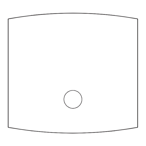
Page 7: Dimension
3.3 Dimension Indicator diagram Status Description BMS No communication 455mm BMS diagram Flashing There is battery voltage, but BMS communication is 213mm abnormal Always on BMS establishes communication 34.5mm 100.8mm Battery not connected (battery voltage not detected) 13.5mm 30mm 105mm 105mm Battery diagram Flashing... -
Page 8: Application
PV string consists of PV modules connected in series range of the equipment manufacturer. Inverter ASG Series Hybrid Inverter • The battery current may be affected by some factors, such as temperature, humidity, weather conditions, etc., which may lead to battery current limiting and affect the... -
Page 9: Application Mode
4.2 Application mode 4.2.2 UPS mode 4.2.1 Self-Use Watch out: • It is applicable to areas with important load and unstable power grid. Watch out: • All energy priorities are to ensure that the battery reserves energy as much as possible to It is applicable to regions with high electricity cost, low electricity sales revenue and ensure that off-grid output loads can be powered in case of grid abnormality. -
Page 10: Function Characteristics
4.3 Function characteristics 4.2.3 peak load shifting 4.3.1 Power derating Watch out: The economic mode can only be selected if the local laws and regulations are met. • In order to make the inverter operate safely, the inverter will automatically reduce the output power when For example, if the power grid is prohibited to charge the battery, do not use this the operating environment is not ideal. -
Page 11: Installation
5 INSTALLATION 5.1.2 Carrier Requirements Installation carriers must not be flammable and must be fire resistant. • • Please make sure that the mounting carrier is solid and reliable and can bear the weight of inverter. 5.1 Installation Requirements The equipment will vibrate during operation, so do not install it on the carrier with poor sound 5.1.1 Environmental requirements insulation, so as to avoid disturbance to residents in the living area caused by the noise generated by •... -
Page 12: Installation Of Inverter
5.2 Installation of inverter 5.1.4 Installation tool requirements The following installation tools are recommended for installation. Other auxiliary tools can be used on 5.2.1 Handling inverter site if necessary. Watch out: • Transportation, turnover, installation and other operations must meet the requirements of national and regional laws and regulations and relevant standards. -
Page 13: Electrical Connection
5.3 Electrical connection 5.3.2 Connecting protective earth wire 5.3.1 Safety precautions Warning: • The protective grounding of the crate shell cannot replace the protective grounding wire of the AC output port. When wiring, ensure that the protective grounding wires at Danger: the two places are reliably connected. - Page 14 5.3.3 Connect PV input line Danger: Do not connect the same PV string to multiple inverters, or the inverter may be • damaged. • Please make sure that the maximum short circuit current and maximum input voltage of each MPPT are within the allowable range of the inverter. 7-10 mm 7-10 mm 22100...
- Page 15 5.3.4 Connect the battery input line Danger: The inverter manufacturer shall approve the battery used with inverter, and the approved battery • list can be obtained through the official website. Short-circuit of battery may cause personal injury. Instantaneous large current caused by short •...
- Page 16 5.3.5 Connecting AC line 7-9mm 7-9mm Danger: • In order to ensure that the inverter and the grid can be safely disconnected from the grid in case of abnormal conditions, please connect the AC switch on the AC side of 20-25mm :13-18mm 20-25mm...
- Page 17 5.3.6 Smart meter (optional) Function Function Watch out: 485A When connecting communication lines, please ensure that the definition of the wiring • port matches the device perfectly, and the cable routing should avoid interference 485B sources, power lines, etc. to avoid affecting signal reception. 485A The electrical meter and CT are shipped with the inverter, and the relevant •...
- Page 18 5.3.7 BMS communication 5.3.8 DRM Control (optional) Watch out: Watch out: • When connecting the communication line, please ensure that the wiring port When connecting the communication line, please ensure that the wiring port • definition is completely matched with the equipment, and the cable route shall avoid definition is completely matched with the equipment, and the cable route shall avoid the interference source, power line, etc.
-
Page 19: Equipment Commissioning And Maintenance
6.3 Set inverter parameters via App Watch out: To ensure that the inverter works properly, please use the AUXSOL application program to complete the inverter parameter setting. Scan the QR code below to download the AUXSOL application or log in https://www.auxsolcloud.com Download this application. -
Page 20: Equipment Removal
6.5 Equipment removal Defect Defect name Solutions codes 1.Restart inverter Danger: Bus over voltage 2.If it still fails after restarting, contact the installer. • Make sure inverter is power off. Off-grid mode: • Wear personal protective equipment when operating the inverter. 1. - Page 21 Defect Defect Defect name Solutions Defect name Solutions codes codes 1. Restart inverter 1. Restart inverter Inverter high voltage 1601 DC current out of limits 2. If it still fails after restarting, contact the installer. 2. If it still fails after restarting, contact the installer. Disconnect the off-grid load and restart the inverter.
-
Page 22: Regular Maintenance
6.8 Regular maintenance Defect Defect name Solutions codes Danger: 3101 Auxiliary source anomaly The machine must be kept power off state during maintenance. Contact the installer. 3202 Control panel wiring abnormality Watch out: 1. Restart inverter 3303 Relay failure Regular maintenance can maintain the stability of inverter performance. 2. -
Page 23: Technical Parameter
7 TECHNICAL PARAMETER Output AC (Grid side) Model ASG-3.6SL-ZH ASG-4SL-ZH ASG-4.6SL-ZH ASG-5SL-ZH ASG-6SL-ZH Rated output power 3.6kW 4.6kW Input DC Max. apparent 3.96kVA 4.4kVA 4.96kVA 5.5kVA 6.6kVA Max.input voltage 550V output power Rated voltage Rated grid voltage 220 V / 230 V 360V MPPT voltage range 90-520V... - Page 24 Efficiency General Data Max.effciency Dimensions (W*H*D) 455 x 462 x 214mm 98.10% EU efficiency Weight 19kg 97.30% BAT charged by PV Max. efficiency 98.50% Self consumption(night) ≤13W -30...+60℃ BAT charged/discharged to AC Max. efficiency 97.60% Operating temperature range Cooling concept Natural Cooling MPPT Efficiency 99.80%...
Need help?
Do you have a question about the ASG Series and is the answer not in the manual?
Questions and answers