AUXSOL ASN Series Installation & Operation Manual
Hide thumbs
Also See for ASN Series:
- Installation & operation manual (24 pages) ,
- Installation and operation manual (28 pages)
Table of Contents
Advertisement
Quick Links
Ningbo AUX Solar Technology Co., Ltd.
No.17 Fenglin Road, Cicheng Town, Jiangbei District, Ningbo City,
Zhejiang Province, China
86-574-8765-2201
www.auxsol.com
info@auxsol.com
INSTALLATION
OPERATION MANUAL
ASN series
ASN - 5TL
ASN - 6TL
ASN - 8TL
ASN - 10TL
ASN - 12TL
Ningbo AUX Solar Technology Co., Ltd.
ASN - 15TL
ASN - 17TL
ASN - 20TL
ASN - 23TL
ASN - 25TL
Advertisement
Table of Contents

Related Manuals for AUXSOL ASN Series


Summary of Contents for AUXSOL ASN Series
- Page 1 INSTALLATION OPERATION MANUAL ASN series ASN - 5TL ASN - 15TL ASN - 6TL ASN - 17TL ASN - 8TL ASN - 20TL ASN - 10TL ASN - 23TL ASN - 12TL ASN - 25TL Ningbo AUX Solar Technology Co., Ltd.
-
Page 2: Table Of Contents
CONTENT PREFACE Summary Applicable products Applicable staff Symbol definition 1 OPEN THE CARTON TO CHECK 1.1 Inspection before acceptance 1.2 Packing list 1.3 Storage 2 SAFETY PRECAUTIONS 2.1 General safety 2.2 PV string safety 2.3 Inverter safety 2.4 Personnel requirements 3 INTRODUCTION 3.1 Products introduction 3.2 Outlook introduction... -
Page 3: Preface
Please obtain the latest version of the information and other product information from the official website. 4.3 Application mode 4.4 Function characteristics Applicable products This document is applicable to the following 10 types of AUX ASN series three-phase on grid inverter: 5 INSTALLATION ASN - 5TL ASN - 6TL ASN - 8TL... -
Page 4: Open The Carton To Check
1 OPEN THE CARTON TO CHECK Description Model Unit Remark Inverter ASN-5~25TL User manual ASN-5~25TL 1.1 Inspection before acceptance Quick installation manual ASN-5~25TL Before signing for the product, please carefully check the following contents: PV terminals (+, -) pair • Check the outer packaging for any damage, such as deformation, holes, cracks, or other signs that Wall-mounting bracket ASN-5~25TL... -
Page 5: Safety Precautions
2 SAFETY PRECAUTIONS 2.3 Inverter safety Danger: The safety precautions contained in this document must always be observed when operating the equipment. • Please connect the inverter AC cable with the AC wiring terminals provided with the box. If other types of DC wiring terminals are used, serious consequences may be caused, and the equipment Watch out: damage caused thereby is not within the scope of the equipment manufacturer. -
Page 6: Introduction
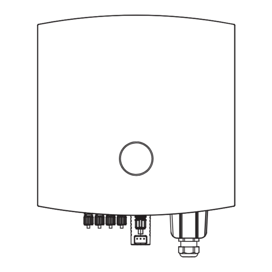
214mm 3.1 Products introduction 100mm The AUX ASN series three-phase on grid inverter integrates the energy management system in the PV 30mm 13.5mm system to control and optimize the energy flow, adapt to the requirements of the smart grid and output... -
Page 7: Application
Transformer Component Description PV string assembly PV string consists of PV modules connected in series Inverter ASN series on grid inverter Used for inverter and load protection and for interrupting AC supply AC circuit breaker during maintenance Smart meter Optional... -
Page 8: Application Mode
5 INSTALLATION 4.3 Application mode 4.3.1 Full grid connection 5.1 Installation requirements If no load is required, all energy of the inverter can be supplied to the utility/national grid to realize full grid connection of power generation. 5.1.1 Environmental requirements •... - Page 9 5.1.2 Carrier requirements 5.1.4 Installation tool requirements The following installation tools are recommended for installation. Other auxiliary tools can be used on • Installation carriers must not be flammable and must be fire resistant. site if necessary. • Please make sure that the mounting carrier is solid and reliable and can bear the weight of inverter. •...
-
Page 10: Installation Of Inverter
5.2 Installation of inverter 5.3 Electrical connection 5.2.1 Handling inverter 5.3.1 Safety precautions Watch out: Danger: • Transportation, turnover, installation and other operations must meet the requirements of national • Specifications of all operation, cables and components used in electrical connection shall comply and regional laws and regulations and relevant standards. - Page 11 5.3.3 Connect PV input cable Danger: • Do not connect the same PV string to multiple inverters, otherwise the inverter may be damaged. • Please make sure that the maximum short circuit current and maximum input voltage of each MPPT are within the allowable range of the inverter. •...
- Page 12 5.3.4 Connecting AC cable Danger: • In order to ensure that the inverter and the grid can be safely disconnected from the grid in case of abnormal conditions, please connect the AC switch on the AC side of the inverter. Multiple inverters cannot be connected to one AC switch at the same time.
- Page 13 5.3.5 Smart meter (optional) ASN three-phase inverter can meet the requirements of zero power export through one intelligent Watch out: • When connecting communication cables, please ensure that the definition of the wiring port meter and three CTs. It can be set as separate phase control and three-phase sum control as required. matches the device perfectly, and the cable routing should avoid interference sources, power Taking 12kW model as an example: cables, etc.
- Page 14 5.3.6 CT anti-reflow (optional) Watch out: ≤100m • When connecting the communication cable, please ensure that the wiring port definition is completely matched with the equipment, and the cable route shall avoid the interference source, power cable, etc. to avoid affecting the signal receiving. Ø10 •...
-
Page 15: Equipment Commissioning And Maintenance
To ensure that the inverter works properly, please use the AUXSOL application program to complete the inverter parameter setting. 6.1 Check before power-on Scan the QR code below to download the AUXSOL application or log in following website to download this application: https://www.auxsolcloud.com Items Checking items... -
Page 16: Equipment Removal
6.5 Equipment removal Defect Defect name Solutions codes Danger: S-phase inverter overcurrent • Make sure inverter is power off. • Wear personal protective equipment when operating the inverter. Check whether the voltage frequency of the T-phase inverter overcurrent power grid is stable. If the power grid Step 1: Successively remove all electrical connections of inverter, including DC cable, AC cable, communication fluctuates greatly, restart the inverter. -
Page 17: Regular Maintenance
Defect Defect Defect name Solutions Defect name Solutions codes codes 1. Confirm whether the insulation of PV input wiring is normal. 1801 PV1 Overvoltage 2901 ISO Fault 2. Wait for the inverter to automatically recover, otherwise Check the configuration of the solar panel to contact the installer. -
Page 18: Technical Parameter
7 TECHNICAL PARAMETER model model ASN - 5TL ASN - 6TL ASN - 8TL ASN - 10TL ASN - 12TL ASN - 15TL ASN - 17TL ASN - 20TL ASN - 23TL ASN - 25TL Input DC Input DC 7.5kW 12kW 15kW 18kW... - Page 19 Protection General Data Integrated DC switch Dimensions (W x H x D) 455 x 462 x 214mm DC rever-polarity protection Weight 25Kg Anti-islanding protection Self consumption(night) <1W Short circuit protection Operating temperature range –30 ... +60°C Output over currentprotection Cooling concept fan-cooling DC Surge protection Type II...
- Page 21 (此页不打印) 打印说明: 1、页面按页码调整为中缝装订,对折后成品页面尺寸:142.5x210mm; 2、封面封底157g 铜版纸彩色打印; 3、正文内容80g双胶纸,双面黑白打印,字体颜色为PANTONE Black C; 4、图面、字体印刷清晰,无乱码、无偏移、无毛边、不起边、油墨不脱落; 5、符合RoHs.
Need help?
Do you have a question about the ASN Series and is the answer not in the manual?
Questions and answers