AUXSOL ASN Series Installation & Operation Manual
Hide thumbs
Also See for ASN Series:
- Installation & operation manual (21 pages) ,
- Installation and operation manual (28 pages)
Table of Contents
Advertisement
Quick Links
Ningbo AUX Solar Technology Co., Ltd.
Ningbo AUX Solar Technology Co., Ltd.
No.17 Fenglin Road, Cicheng Town,
Jiangbei District, Ningbo City, Zhejiang Province, China
info@auxsol.com
www.auxsol.com
+86 0574-8765 2201
INSTALLATION
OPERATION MANUAL
ASN series
ASN - (6~10) SL
Ningbo AUX Solar Technology Co., Ltd.
Advertisement
Table of Contents

Related Manuals for AUXSOL ASN Series


Summary of Contents for AUXSOL ASN Series
- Page 1 INSTALLATION OPERATION MANUAL ASN series ASN - (6~10) SL Ningbo AUX Solar Technology Co., Ltd. Ningbo AUX Solar Technology Co., Ltd. No.17 Fenglin Road, Cicheng Town, Jiangbei District, Ningbo City, Zhejiang Province, China info@auxsol.com www.auxsol.com +86 0574-8765 2201 Ningbo AUX Solar Technology Co., Ltd.
-
Page 2: Table Of Contents
CONTENT PREFACE Summary Applicable products Applicable staff Symbol definition 1 OPEN THE CARTON TO CHECK 1.1 Inspection before acceptance 1.2 Packing list 1.3 Storage 2 SAFETY PRECAUTIONS 2.1 General safety 2.2 PV string safety 2.3 Inverter safety 2.4 Personnel requirements 3 INTRODUCTION 3.1 Products Introduction 3.2 Outlook Introduction... -
Page 3: Preface
Please obtain the latest version of the information and other product information from the official website. 4.3 Function characteristics Applicable products This document is applicable to the following 5 types of AUX ASN series single-phase on grid inverter: 5 INSTALLATION ASN - 6SL ASN - 7SL... -
Page 4: Open The Carton To Check
1 OPEN THE CARTON TO CHECK Description Model Unit Remark Inverter ASN-6~10SL User manual ASN-6~10SL 1.1 Inspection before acceptance Quick installation manual ASN-6~10SL Before signing for the product, please carefully check the following contents: PV terminals (+, -) black • Check the outer packaging for any damage, such as deformation, holes, cracks, or other signs that Wall-mounting bracket ASN-6~10SL... -
Page 5: Safety Precautions
2 SAFETY PRECAUTIONS 2.3 Inverter safety Danger: The safety precautions contained in this document must always be observed when operating the equipment. • Please connect the inverter AC cable with the AC wiring terminals provided with the box. If other types of AC wiring terminals are used, serious consequences may be caused, and the equipment Watch out: damage caused thereby is not within the scope of the equipment manufacturer. -
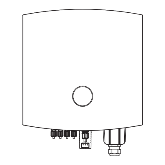
Page 6: Introduction
3.1 Products introduction 105mm 105mm 82mm The AUX ASN series single-phase on grid inverter integrates the energy management system in the PV 13.5mm 30mm system to control and optimize the energy flow, adapt to the requirements of the smart grid and output 94mm the power generated in the PV system to the utility/national grid. - Page 7 3.4.1 LCD (Optional) 3.4.2 LCD Operation Menu YELLOW LED 3.4.2.1 Button The LCD screen display module has two touch buttons. Touch buttons are as follows: GREEN LED RED LED ALARM FAULT Button mode Meaning Touch button 1 LCD SCREEN Touch button 2 DOWN Press and hold button 1 for 2s BACK...
- Page 8 The LCD is located on the front panel of the inverter, which shows the following information: The AUX ASN series single-phase inverter main menu provides access to operating data and information. Select Current Data from the menu to display the information and scroll up or down.
- Page 9 "01" to "10". Only fully qualified and approved technicians shall enter the area. Password is required to enter the The default address number of AUX ASN series single-phase inverter is "01". 1.Comm Addr menu "Contrl Param". Select "Contrl Param" on the Main Menu.The screen will require the Press the UP/ DOWN buttons to set the address.
- Page 10 3.4.9.2 Clear his.error Display Description This function is used to clear the fault record. GridOverVolt_1 Display the primary over voltage protection value of His Elec Clear? 110% Press and hold button 2 for 2s to save the setting , Press and hold button 1 for 2s power grid Cancel affirm...
- Page 11 Press UP/DOWN to manually scroll the screen. Press and hold button 2 for 2s to enter the parameter Display Description modification interface, than press DOWN to move the cursor, press UP to select numbers, press and hold button 2 for 2s to save the settings, press and hold button 1 for 2s to cancel the change and return GridOverVFreq_T1 Display the primary over-frequency protection time of to the previous menu.
-
Page 12: Application
Component Description PV string assembly PV string consists of PV modules connected in series Inverter ASN series on grid inverter 4.3 Function characteristics Used for inverter and load protection and for interrupting AC supply AC circuit breaker during maintenance 4.3.1 Power derating... -
Page 13: Installation
5 INSTALLATION 5.1.2 Carrier requirements • Installation carriers must not be flammable and must be fire resistant. • Please make sure that the mounting carrier is solid and reliable and can bear the weight of inverter. 5.1 Installation requirements • The equipment will vibrate during operation, so do not install it on the carrier with poor sound insulation, 5.1.1 Environmental requirements so as to avoid disturbance to residents in the living area caused by the noise generated by the... -
Page 14: Installation Of Inverter
5.2 Installation of inverter 5.1.4 Installation tool requirements The following installation tools are recommended for installation. Other auxiliary tools can be used on 5.2.1 Handling inverter site if necessary. Watch out: • Transportation, turnover, installation and other operations must meet the requirements of national and regional laws and regulations and relevant standards. -
Page 15: Electrical Connection
5.3 Electrical connection 5.3.2 Connecting protective earth wire Warning: 5.3.1 Safety precautions • The protective grounding of the crate shell cannot replace the protective grounding wire of the AC output port. When wiring, ensure that the protective grounding wires Danger: at the two places are reliably connected. - Page 16 5.3.3 Connect PV input cable Danger: • Do not connect the same PV string to multiple inverters, otherwise the inverter may be damaged. • Please make sure that the maximum short circuit current and maximum input voltage 7-10 mm 7-10 mm crimping pliers of each MPPT are within the allowable range of the inverter.
- Page 17 5.3.4 Connecting AC cable Note: 1. Single core wire, no terminal pressing operation required. 2. For multi-core wires, cold-pressed terminal crimping pliers shall be used for crimping terminals. Danger: • In order to ensure that the inverter and the grid can be safely disconnected from the grid in case of abnormal conditions, please connect the AC switch on the AC side of the inverter.
- Page 18 5.3.5 CT Anti-reflow (optional) 5.3.6 Smart meter (optional) Watch out: Watch out: • When connecting signal cables, the cable route shall avoid interference sources, power cables, When connecting communication cables, please ensure that the definition of the • etc. to avoid affecting signal reception. •...
- Page 19 5.3.7 DRM Control (optional) Watch out: • When connecting communication cables, please ensure that the definition of the wiring port matches the device perfectly, and the cable routing should avoid interference sources, power cables, etc. to avoid affecting signal reception. •...
-
Page 20: Equipment Commissioning And Maintenance
To ensure that the inverter works properly, please use the AUXSOL application program to complete the inverter parameter setting. 6.1 Check before power-on Scan the QR code below to download the AUXSOL application or log in following website to download this application: https://www.auxsolcloud.com Items Checking items... -
Page 21: Equipment Removal
6.5 Equipment removal Defect Defect name Solutions codes Danger: Bus over voltage • Make sure inverter is power off. • Wear personal protective equipment when operating the inverter. Bus under voltage 1. Restart inverter. Step 1: Successively remove all electrical connections of inverter, including DC cable, AC cable, 2. -
Page 22: Regular Maintenance
Defect Defect Defect name Solutions Defect name Solutions codes codes 2101 PV Input arc protection 3101 Auxiliary source anomaly Contact the installer. Disconnect the inverter PV/grid input and check whether the wiring from the solar panel to the inverter input terminal is damaged/in poor 1. -
Page 23: Technical Parameter
7 TECHNICAL PARAMETER Model ASN - 6SL ASN - 7SL ASN - 8SL ASN - 9SL ASN - 10SL Model ASN - 6SL ASN - 7SL ASN - 8SL ASN - 9SL ASN - 10SL input DC Efiiciency Max.input power 10.5kW 12kW 18kW... - Page 24 Modelo ASN - 6SL ASN - 7SL ASN - 8SL ASN - 9SL ASN - 10SL General Data Dimensions (W*H*D) 400 x 383 x 177mm Weight 15.6kg 15.6kg 15.6kg 15.6kg 15.6kg Self consumption(night) ≤0.3W ≤0.3W ≤0.3W ≤1W ≤1W Operating temperature range -30...+60°C -30...+60°C -30...+60°C...
Need help?
Do you have a question about the ASN Series and is the answer not in the manual?
Questions and answers