
Subscribe to Our Youtube Channel
Related Manuals for Lincoln Electric PRESTO 275


Summary of Contents for Lincoln Electric PRESTO 275
- Page 1 SVM 3137 Rev.00 04-2022 PRESTO ® For use with machines having code numbers: 50537 LINCOLN ELECTRIC EUROPE www.lincolnelectric.eu...
-
Page 2: Table Of Contents
INDEX OF CONTENTS INDEX OF CONTENTS ............................2 TECHNICAL SPECIFICATIONS ........................3 ELECTROMAGNETIC COMPATIBILITY (EMC) ....................4 SAFETY ................................5 MAINTENANCE ..............................2 MAJOR COMPONENTS LOCATION ........................ 3 THEORY OF OPERATION ..........................4 INPUT SECTION ..............................5 INVERTER AND OUTPUT SECTIONS ......................6 CONTROL BOARD –... -
Page 3: Technical Specifications
Technical Specifications NAME INDEX PRESTO 275 W100000001 INPUT Input Voltage U EMC Class 400V +/- 15% 3 phases PRESTO 275 1eff 1max 9.8A 15,3A Input Power at Rated Cycle Input Amperes I PF (400V) 1max 7,1 kVA (@100%) 10,1A 0,79... -
Page 4: Electromagnetic Compatibility (Emc)
Provided that the public low voltage system impedance at the point of common coupling is lower than: 64,8mΩ for the PRESTO 275 This equipment is compliant with IEC 61000-3-11 and IEC 61000-3-12 and can be connected to public low voltage systems. -
Page 5: Safety
Failure to follow the instructions in this manual could cause serious personal injury, loss of life, or equipment damage. Read and understand the following explanations of the warning symbols. Lincoln Electric is not responsible for damages caused by improper installation, improper care or abnormal operation. - Page 6 WELDING SPARKS CAN CAUSE FIRE OR EXPLOSION: Remove fire hazards from the welding area and have a fire extinguisher easily accessible. Welding sparks and hot materials from the welding process can easily go through small cracks and openings to adjacent areas. Do not weld on any tanks, drums, containers, or material until the proper steps have been taken to insure that no flammable or toxic vapors will be present.
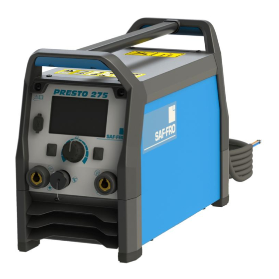
- Page 7 Introduction PRESTO 275 is a SMAW and GTAW power source Recommended equipment, which can be bought by user, was mentioned in the "Accessories" chapter. The complete package contains: Power source USB with operator’s manual. Installation and Operator Instructions...
- Page 8 Controls and Operational User Interface Features Front panel PRESTO 275 Figure 3 2. Display: 5” TFT display shows welding processes parameters. 3. Left button: Home & Back 4. Central Knob: Parameter access and validation by pushing knob 5. Right Button: Access to specific parameter of the current selected page.
- Page 9 Home menu Home Menu description Primary settings Status Bar Voltage Preset current Secondary settings Contextual Buttons / Encoders Labels Figure 6 Figure 5 1. “Main Menu” access, push this button to go back. 1. In “Primary Settings” area, the type of process and corresponding information will be indicated like 2.
- Page 10 Remote control Welding SMAW process Figure 9 Figure 10 In GTAW mode, 2 accessories can be selected: To select, stick mode process, select the SMAW icon Hand remote control and push the knob button. Pedal Remote control. Home menu See “Accessories”...
- Page 11 Figure 13 Figure 15 The machine allow the user the use 4 stick mode: Anti-Sticking Soft: For a welding with a low spatter presence. Hot This feature cannot be modified by user. Start and Arc Force are pre-defined and can not be modified This is a function that decreases the output current of the ...
- Page 12 Accessories Accessories can be accessed in GTAW and SMAW by pushing knob button and selecting “Remote Control” icon and push knob again. Figure 19 Figure 17 When activated, a new icon appears on the right of “Remote Control” icon named “Remote range”. Figure 18 Hand Remote Usable for GTAW and SMAW process.
- Page 13 Memories Guided Setup Welding process and all parameters which belongs to Guide Setup is a feature for SMAW which configures cycle can be saved in a memory slot in order to be automatically the power source according to a set of recalled after.
- Page 14 Current range ribbon The machine automatically configures the best current value. It is also possible to adjust the current around this value. As soon as the current remains in proper welding current range for the application, If the current exceed the proposer welding range, the ribbon turned into red indicating to the user the current selectin is not the best one.
- Page 15 For any repair operations, modifications or maintenances, it is recommended to contact the Advanced Settings System Information. nearest Technical Service Center or Lincoln Electric. The software revision are displayed in this section. Repairs and modifications performed by unauthorized service or personnel will cause, that the manufacturer’s Factory Reset allows to reset the power source warranty will be lost.
- Page 16 Error Codes and troubleshooting When the error occurs and remains, the Error messages Error is displayed in Red. code Type of error When the error vanished, it is now possible to acknowledge the error by pushing the knob. The background error message becomes white By pushing the knob button, the Error code number is “Done”, displayed.
-
Page 17: Maintenance
MAINTENANCE WARNING DC BUS CAPACITORS DISCHARGE PROCEDURE ® 1. Remove input power to the PRESTO ELECTRIC SHOCK can kill 2. Remove the side panels following the instruction available in this Service Manual. Have an electrician install and service this equipment 3. -
Page 18: Major Components Location
MAJOR COMPONENTS LOCATION ® PRESTO 1. Main Switch (S1) 9. Output Transformer (T2) 2. EMC Filter Board 10. Output Current Transducer 3. Fans 11. Control Board 4. Input Rectifier 12. TFT UI Board 5. Preload PCB 6. Inverter 7. Aux. Power Supply Board 8. -
Page 19: Theory Of Operation
THEORY OF OPERATION 275 – WIRING DIAGRAM ® PRESTO GENERAL DESCRIPTION ® The PRESTO 275 is an inverter based welding power Thanks to their IP23 rating and potted boards this source that offer multi-mode (STICK and LIFT TIG) power source can be used in both factory or field constant current welding. -
Page 20: Input Section
INPUT SECTION INPUT SECTION When the three phase input voltage 400Vac is applied monitors the input voltage and if all is correct provides ® to the PRESTO 275 and the input switch S1 is closed the command to the relay on the Preload board to the voltage is applied to the Input EMI filter board. -
Page 21: Inverter And Output Sections
INVERTER AND OUTPUT SECTIONS INVERTER AND OUTPUT CIRCUITS, MAIN TRANSFORMER AND OUTPUT SECTIONS The inverter board receives the rectified primary power The output choke provides filtering to enhance the arc from the Preload Board (565Vdc) and it converts this performance and accurate waveform response. power from DC to AC high frequency that is applied to the primary windings of the main welding transformer The current transducer provides an accurate feedback... -
Page 22: Control Board - Tft Ui Board
CONTROL BOARD – TFT UI BOARD CONTROL BOARD AND TFT UI BOARD The Control Board managing all the functions of the machine, a microprocessor is present on it to make the correct operations. The Control Board receives signals from different area of the machine, power supply from Aux. - Page 23 duty cycle and output rating. If excessive operating OVERLOAD PROTECTION temperature should occur, the Thermal LED indicator on the front panel, will turn ON and the thermostat will ® PRESTO 275 is electrically protected from producing prevent output current. higher output currents. An electronic protection circuit limits the current to within the capabilities of the The thermal protections are self-resetting once the machine.
- Page 24 INSULATED GATE BIPOLAR TRANSISTOR (IGBT) OPERATION Drawing B shows the IGBT in an active mode. An IGBT is a type of transistor. IGBTs are When the gate signal, a positive DC voltage semicon-ductors well suited for high frequency relative to the source, is applied to the gate switching and high current applications.
-
Page 25: Troubleshooting And Repair Section
TROUBLESHOOTING AND REPAIR SECTION How to use troubleshooting Guide Troubleshooting Guide Case cover removal and capacitor discharge procedure EMI filter board resistance test Input rectifier resistance test Inverter board and output diodes resistance test ... -
Page 26: How To Use Troubleshooting Guide
HOW TO USE TROUBLESHOOTING GUIDE Service and repair should be performed by only Lincoln Electric Factory Trained Personnel. Unauthorized repairs performed on this equipment may result in danger to the technician and machine operator and will invalidate your factory warranty. For your safety and to avoid Electrical Shock, please observe all safety notes and precautions detailed throughout this manual. - Page 27 WARNING NOTE: Allow the machine to heat up so that all electrical components can reach their operating temperature. 5. Remove the replacement PC board and ELECTRIC SHOCK can kill substitute it with the original PC board to recreate the original problem. ...
- Page 28 PERFORM THE FANS TEST These tests and repair should only be performed by Lincoln Electric Factory Trained Personnel. Unauthorized repairs performed on this equipment may result in danger to the technician and machine operator and will invalidate your factory warranty. For your safety and to avoid Electrical Shock, please...
-
Page 29: Case Cover Removal And Dc Bus Capacitor Discharge Procedure
DISCHARGE PROCEDURE WARNING Service and repair should be performed only by Lincoln Electric factory trained personnel.Unauthorized repairs performed on this equipment may result in danger to the technician or machine operator and will invalidate your factory warranty. For your safety and to avoid electrical shock, please observe all safety notes and precautions detailed throughout this manual. -
Page 30: Presto ® 275 - Side Panels Removal
® PRESTO 275 - SIDE PANELS REMOVAL Bottom view Procedure: 1. Turn ON/OFF switch to OFF position. 2. Disconnect Input Power from the machine ! 3. Using the TORX wrench TX-25 driver, remove the 4 screws (A) on the bottom of machine 4. -
Page 31: Dc Bus Capacitors Discharge Procedure
DC BUS CAPACITORS DISCHARGE PROCEDURE DC BUS CAPACITORS DISCHARGE WARNING PROCEDURE ® 1. Remove input power to the PRESTO 2. Remove the side panels following the instruction available in this Service manual. ELECTRIC SHOCK can kill 3. Obtain a high resistance and high wattage resistor (25-1000 ohms and 25 watts minimum). -
Page 32: Emi Filter Board Resistance Test
EMI FILTER BOARD RESISTANCE TEST WARNING Service and repair should be performed by only Lincoln Electric factory trained personnel. Unauthorized repairs performed on this equipment may result in danger to the technician or machine operator and will invalidate your factory warranty. For your safety and to avoid electrical shock, please observe all safety notes and precautions detailed throughout this manual. - Page 33 EMI FILTER BOARD RESISTANCE TEST (continued) Figure 2 EMI FILTER BOARD Figure 2a TEST PROCEDURE Use always electrically insulate gloves during this test procedure ® 1. Remove main input power to the PRESTO 2. Perform the Side Panels removal and Discharge procedure 3.
-
Page 34: Input Rectifier Resistance Test
INPUT RECTIFIER RESISTANCE TEST WARNING Service and repair should be performed by only Lincoln Electric factory trained personnel. Unauthorized repairs performed on this equipment may result in danger to the technician or machine operator and will invalidate your factory warranty. For your safety and to avoid electrical shock, please observe all safety notes and precautions detailed throughout this manual. - Page 35 INPUT RECTIFIER RESISTANCE TEST (continued) DC - DC + Figure 3 – Input Rectifier Bridge location and Test Points TEST PROCEDURE Use always electrically insulate gloves during this test procedure ® 1. Remove main input power to the PRESTO 275. 2.
-
Page 36: Inverter Board And Output Diodes Resistance Test
INVERTER BOARD AND OUTPUT DIODES RESISTANCE TEST WARNING Service and repair should be performed by only Lincoln Electric factory trained personnel. Unauthorized repairs performed on this equipment may result in danger to the technician or machine operator and will invalidate your factory warranty. - Page 37 INVERTER BOARD AND OUTPUT DIODES RESISTANCE TEST (continued) Figure 4 – Inverter Board location and Test Points TEST PROCEDURE Use always electrically insulate gloves during this test procedure ® 1. Remove main input power to the PRESTO 275. 2. Perform the Side Panels removal and Discharge procedure 3.
- Page 38 INVERTER BOARD AND OUTPUT DIODES RESISTANCE TEST (continued) Figure 5 – Output Diodes location and Test Points TEST PROCEDURE Use always electrically insulate gloves during this test procedure 1. Remove main input power to the PRESTO ® 275. 2. Perform the Side Panels removal and Discharge procedure 3.
-
Page 39: Thermal Protection Resistance Test
THERMAL PROTECTION RESISTANCE TEST WARNING Service and repair should be performed by only Lincoln Electric factory trained personnel. Unauthorized repairs performed on this equipment may result in danger to the technician or machine operator and will invalidate your factory warranty. For your safety and to avoid electrical shock, please observe all safety notes and precautions detailed throughout this manual. - Page 40 THERMAL PROTECTION RESISTANCE TEST (continued) (NTC1) (NTC2) Figure 7 – NTC Thermal sensors connectors location TEST PROCEDURE Use always electrically insulate gloves during this test procedure ® 1. Remove main input power to the PRESTO 275. 2. Perform the Side Panels removal and Discharge procedure 3.
-
Page 41: Output Studs Resistance Test
OUTPUT STUDS RESISTANCE TEST WARNING Service and repair should be performed by only Lincoln Electric factory trained personnel. Unauthorized repairs performed on this equipment may result in danger to the technician or machine operator and will invalidate your factory warranty. For your safety and to avoid electrical shock, please observe all safety notes and precautions detailed throughout this manual. - Page 42 OUTPUT STUDS RESISTANCE TEST (continued) Positive Stud Negative Stud Figure 8 – Output studs location TEST PROCEDURE Use always electrically insulate gloves during this test procedure ® 1. Remove main input power to the PRESTO 275. 2. Perform the Side Panels removal and Discharge procedure 3.
-
Page 43: Emi Filter Board Voltage Test
EMI FILTER BOARD VOLTAGE TEST WARNING Service and repair should be performed by only Lincoln Electric factory trained personnel. Unauthorized repairs performed on this equipment may result in danger to the technician or machine operator and will invalidate your factory warranty. For your safety and to avoid electrical shock, please observe all safety notes and precautions detailed throughout this manual. - Page 44 EMI FILTER BOARD VOLTAGE TEST (continued) Figure 9 EMI FILTER BOARD Figure 9a TEST PROCEDURE Use always electrically insulate gloves during this test procedure 1. Remove main input power to the PRESTO ® 275. 2. Perform the Side Panels removal and Discharge procedure available in this Service Manual ®...
-
Page 45: Input Rectifier Voltage Test
INPUT RECTIFIER VOLTAGE TEST WARNING Service and repair should be performed by only Lincoln Electric factory trained personnel. Unauthorized repairs performed on this equipment may result in danger to the technician or machine operator and will invalidate your factory warranty. For your safety and to avoid electrical shock, please observe all safety notes and precautions detailed throughout this manual. - Page 46 INPUT RECTIFIER VOLTAGE TEST (continue) DC - DC + Figure 10 – Input Rectifier Bridge location and Test Points TEST PROCEDURE Use always electrically insulate gloves during this test procedure ® 1. Remove main input power to the PRESTO 275. 2.
-
Page 47: Preload Board Voltage Test
PRELOAD BOARD VOLTAGE TEST WARNING Service and repair should be performed by only Lincoln Electric factory trained personnel. Unauthorized repairs performed on this equipment may result in danger to the technician or machine operator and will invalidate your factory warranty. For your safety and to avoid electrical shock, please observe all safety notes and precautions detailed throughout this manual. - Page 48 PRELOAD BOARD VOLTAGE TEST (continued) Figure 11 – Preload Board location and Test Points TEST PROCEDURE Use always electrically insulate gloves during this test procedure ® 1. Remove main input power to the PRESTO 275. 2. Perform the Side Panels removal and Discharge procedure available in this Service Manual ®...
-
Page 49: Aux. Power Supply Board Voltage Test
AUX. POWER SUPPLY BOARD VOLTAGE TEST WARNING Service and repair should be performed by only Lincoln Electric factory trained personnel. Unauthorized repairs performed on this equipment may result in danger to the technician or machine operator and will invalidate your factory warranty. - Page 50 AUX. POWER SUPPLY BOARD VOLTAGE TEST (continue) LED5 LED2 LED1 LED3 LED4 Figure 12 – AUX. Power Supply Board location and Test Points TEST PROCEDURE WARNING: Black heatsink in on primary side: Do not touch it. Use always electrically insulate gloves during this test procedure ®...
-
Page 51: Inverter And Output Board Voltage Test
INVERTER AND OUTPUT BOARD VOLTAGE TEST WARNING Service and repair should be performed by only Lincoln Electric factory trained personnel. Unauthorized repairs performed on this equipment may result in danger to the technician or machine operator and will invalidate your factory warranty. - Page 52 INVERTER AND OUTPUT BOARD VOLTAGE TEST (continue) Figure 13 – Inverter Board location and Test Points TEST PROCEDURE Use always electrically insulate gloves during this test procedure 1. Remove main input power to the PRESTO ® 275. 2. Perform the Side Panels removal and Discharge procedure available in this Service Manual ®...
-
Page 53: Control Board Voltage Test
CONTROL BOARD VOLTAGE TEST WARNING Service and repair should be performed by only Lincoln Electric factory trained personnel. Unauthorized repairs performed on this equipment may result in danger to the technician or machine operator and will invalidate your factory warranty. For your safety and to avoid electrical shock, please observe all safety notes and precautions detailed throughout this manual. - Page 54 CONTROL BOARD VOLTAGE TEST (continue) Figure 14 – Control Board location and Test Points LED1 LED6 LED5 LED2 LED7 LED8 LED4 LED9 LED3 TEST PROCEDURE Use always electrically insulate gloves during this test procedure 1. Remove main input power to the PRESTO ®...
- Page 55 CONTROL BOARD VOLTAGE TEST (continue) Figure 15 – Control Board location and Test Points TEST PROCEDURE Use always electrically insulate gloves during this test procedure 1. Remove main input power to the PRESTO ® 275. 2. Perform the Side Panels removal and Discharge procedure available in this Service Manual ®...
-
Page 56: Disassembly Operations
DISASSEMBLY OPERATIONS UPPER AND REAR PLASTIC PANEL REMOVAL PROCEDURE WARNING Disconnect input power before servicing. Do not operate with covers removed. Do not touch electrically live parts. Only qualified persons should install, use ELECTRIC SHOCK or service this equipment. CAN KILL Figure 16 Figure 17 Figure 18... - Page 57 DISASSEMBLY OPERATIONS EMI FILTER REMOVAL AND REPLACEMENT PROCEDURE WARNING B4, B5, B6 Disconnect input power before servicing. (OUTPUT) Do not operate with covers removed. Do not touch electrically live parts. Only qualified persons should install, use ELECTRIC SHOCK or service this equipment. CAN KILL Figure 19 B1, B2,...
- Page 58 DISASSEMBLY OPERATIONS PRELOAD BOARD REMOVAL AND REPLACEMENT PROCEDURE Figure 21 Figure 22 REMOVAL PROCEDURE Necessary tools: Screwdriver PH02 Socket wrench 7mm ® 1. Remove main input power to the PRESTO 275. 2. Perform the Discharge procedure. 3. Locate the Preload Board. See Figure 21 4.
- Page 59 DISASSEMBLY OPERATIONS INPUT RECTIFIER BRIDGE REMOVAL AND REPLACEMENT PROCEDURE Figure 24 Figure 23 REMOVAL PROCEDURE Necessary tools: Screwdriver PH02 ® 1. Remove main input power to the PRESTO 275. 2. Perform the Discharge procedure. 3. Locate the Input Rectifier Bridge. See Figure 23 4.
- Page 60 DISASSEMBLY OPERATIONS INVERTER AND OUTPUT BOARD REMOVAL AND REPLACEMENT PROCEDURE WARNING Disconnect input power before servicing. Do not operate with covers removed. Do not touch electrically live parts. Only qualified persons should install, use ELECTRIC SHOCK or service this equipment. CAN KILL Figure 26 Figure 27...
- Page 61 DISASSEMBLY OPERATIONS AUXILIARY POWER BOARD REMOVAL AND REPLACEMENT PROCEDURE WARNING Disconnect input power before servicing. Do not operate with covers removed. Do not touch electrically live parts. Only qualified persons should install, use ELECTRIC SHOCK or service this equipment. CAN KILL Figure 29 Figure 30 REMOVAL PROCEDURE...
- Page 62 DISASSEMBLY OPERATIONS CONTROL BOARD REMOVAL AND REPLACEMENT PROCEDURE Figure 31 REMOVAL PROCEDURE Necessary tools: Socket wrench 7mm ® 1. Remove main input power to the PRESTO 275. 2. Perform the Discharge procedure. 3. Locate the Control Board. See Figure 31 4.
- Page 63 DISASSEMBLY OPERATIONS UI-TFT BOARD REMOVAL AND REPLACEMENT PROCEDURE Figure 32 Figure 33 Figure 34 REMOVAL PROCEDURE Necessary tools: 5,5mm wrench 2mm allen wrench 10mm wrench ® 1. Remove main input power to the PRESTO 275. 2. Perform the Discharge procedure. 3.
- Page 64 DISASSEMBLY OPERATIONS ON/OFF SWITCH REMOVAL AND REPLACEMENT PROCEDURE Figure 38 Figure 37 Figure 39 REMOVAL PROCEDURE Necessary tools: Screwdriver PH02 ® 1. Remove main input power to the PRESTO 275. 2. Perform the Discharge procedure. 3. Locate the ON/OFF switch on the backside of the machine. See Figure 37 4.
- Page 65 DISASSEMBLY OPERATIONS FANS REMOVAL AND REPLACEMENT PROCEDURE Figure 43 Figure 42 Figure 44 Figure 45 Figure 46 REMOVAL PROCEDURE Necessary tools: PH02 screwdriver TX25 wrench 7mm wrench ® 1. Remove main input power to the PRESTO 275. 2. Perform the Discharge procedure. 3.
- Page 66 DISASSEMBLY OPERATIONS FANS REMOVAL AND REPLACEMENT PROCEDURE (CONTINUE) Figure 47 Figure 48 Figure 49 Figure 50 10. Using the TX25 wrench remove the 2 screws (F) on the bottom of the machine, See Figure 47 11. Using the PH02 scredriver remove the screw (G). See Figure 48 12.
-
Page 67: Retest After Repair
RETEST AFTER REPAIR Should a machine under test be rejected for any reason requiring the removal of any mechanical part that could affect the machine’s electrical characteristics, or if any electrical components are repaired or replaced, the machine must be retested. -
Page 68: Electrical Schematics
ELECTRICAL SCHEMATICS ® Schematic Diagram: PRESTO... -
Page 69: Error Codes
ERROR CODES Security Description Manufacturer specific Error code Primary Over Current =331 Secondary Over Current (short average) Secondary current probe failure Power Supply Over Voltage =341 Power Supply Under Voltage =342 Preload Time Out =337 Primary Over Power =338 Primary Thermal Secondary Thermal Cooler =266... -
Page 70: Note
NOTE...
Need help?
Do you have a question about the PRESTO 275 and is the answer not in the manual?
Questions and answers