Table of Contents
Advertisement
Quick Links
Operator's Manual
Prism 4
®
Register your machine:
www.lincolnelectric.com/register
Authorized Service and Distributor Locator:
www.lincolnelectric.com/locator
Save for future reference
Date Purchased
Code: (ex: 10859)
Serial: (ex: U1060512345)
IM10635
| Issue D ate Mar - 22
© Lincoln Global, Inc. All Rights Reserved.
For use with machines having Code Numbers:
13308, 13309, 13311, 13312,
13313, 13314
Need Help? Call 1.888.935.3877
to talk to a Service Representative
Hours of Operation:
8:00 AM to 6:00 PM (ET) Mon. thru Fri.
After hours?
Use "Ask the Experts" at lincolnelectric.com
A Lincoln Service Representative will contact you
no later than the following business day.
For Service outside the USA:
Email: globalservice@lincolnelectric.com
Advertisement
Table of Contents
Troubleshooting

Related Manuals for Lincoln Electric Prism 4


Summary of Contents for Lincoln Electric Prism 4
- Page 1 Operator’s Manual Prism 4 ® For use with machines having Code Numbers: 13308, 13309, 13311, 13312, 13313, 13314 Need Help? Call 1.888.935.3877 Register your machine: to talk to a Service Representative www.lincolnelectric.com/register Authorized Service and Distributor Locator: Hours of Operation: www.lincolnelectric.com/locator...
- Page 2 THANK YOU FOR SELECTING A QUALITY PRODUCT BY KEEP YOUR HEAD OUT OF THE FUMES. DON’T get too close to the arc. LINCOLN ELEC TRIC. Use corrective lenses if necessary to stay a reasonable distance away from the arc. READ and obey the Safety Data PLEASE EXAMINE CARTON AND EQUIPMENT FOR Sheet (SDS) and the warning label DAMAGE IMMEDIATELY...
- Page 3 P.O. Box 351040, Miami, Florida 33135 or CSA Standard W117.2. A Free copy of “Arc Welding Safety” booklet E205 2.a. Electric current owing through any conductor is available from the Lincoln Electric Company, 22801 causes localized Electric and Magnetic Fields (EMF). St. Clair Avenue, Cleveland, Ohio 44117-1199.
- Page 4 SAFETY ELECTRIC SHOCK ARC RAYS CAN BURN. CAN KILL. 3.a. The electrode and work (or ground) circuits are 4.a. Use a shield with the proper filter and cover plates to protect your electrically “hot” when the welder is on. Do eyes from sparks and the rays of the arc when welding or not touch these “hot”...
- Page 5 SAFETY WELDING AND CUTTING CYLINDER MAY EXPLODE IF SPARKS CAN CAUSE DAMAGED. FIRE OR EXPLOSION. 7.a. Use only compressed gas cylinders containing the correct shielding gas for the process used 6.a. Remove fire hazards from the welding area. If and properly operating regulators designed for this is not possible, cover them to prevent the welding sparks the gas and pressure used.
- Page 6 SAFETY PRISM® 4 As a rule of thumb, for many mild steel electrode, if the air is (Permissible Exposure Limit), and the recommended guideline, the visibly clear and you are comfortable, then the ventilation is ACGIH TLV (Threshold Limit Value), for many compounds found in generally adequate for your work.
- Page 7 TLV and PEL values are as of October 2013. Always check Safety and 313 of the Emergency Planning and Community Right- Data Sheet (SDS) with product or on the Lincoln Electric website at to-Know Act of 1986 and of 40CFR 370 and 372.
-
Page 8: Table Of Contents
PRISM® 4 TABLE OF CONTENTS INSTALLATION .............................SECTION A TECHNICAL SPECIFICATIONS .............................A-1 GENERAL DESCRIPTION.............................A-2 THE INTENDED PURPOSE............................A-2 TRANSPORT AND ERECTION ............................A-2 SELECT SUITABLE LOCATION.............................A-2 ENVIRONMENTAL AREA .............................A-2 INSTALLATION OF PRISM® 4.............................A-3 ELECTRICAL CONNECTIONS............................A-7 RELOCATE CONTROL PANEL TO RIGHT SIDE......................A-7 OPERATION ..............................SECTION B USERS ................................B-1 INTENDED USE ................................B-1... -
Page 9: Technical Specifications
AND QUALITY clean, dry and oil free MAXIMUM RELATIVE HUMIDITY PRISM® 4 AIR CONSUMPTION PRISM® 4: AD1326-17 & AD1326-20 INPUT VOLTAGE NOMINAL 6 BAR / 87 PSI Prism 4 380-480V/3~/50-60Hz +/- 10% Recommended (1 valve per pulse) MAXIMUM CURRENT 7.5 A... -
Page 10: General Description
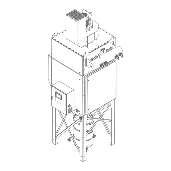
INSTALLATION PRISM® 4 INSTALLATION WARNING Excluded Uses! GENERAL DESCRIPTION • Welding fumes containing oil • Aluminium dust Prism® 4 is a reduced-footprint fan/ ltration unit combination designed with robotic welding and plasma cutting systems in • Burning or incandescent materials mind. -
Page 11: Installation Of Prism® 4
INSTALLATION PRISM® 4 Step 2 – Lift Main Body Into Vertical Position INSTALLATION OF PRISM® 4 FIGURE A.2 Rest unit on 4 x 4 TOOLS NEEDED blocks to protect Lift unit control wires vertical by • 5/16" Nutdriver strapping 4 x 4 wood •... - Page 12 INSTALLATION PRISM® 4 Step 3 – Install Main Module On Leg Base/Hopper Lift main module on top of leg base. FIGURE A.5 FIGURE A.4 Place leg base hopper assembly in desired position, then apply strip foam gasket (supplied in hopper carton) completely around top of hopper ange as shown.
- Page 13 INSTALLATION PRISM® 4 Step 4 – Install Fan Silencer STEP 6 – COMPRESSED AIR CONNECTIONS FIGURE A.6 FIGURE A.8 Apply strip foam gasket on inside of bolt holes and overlap in corners. Install silencer using 3/8 bolts and nuts. AD1326-17: (8 BOLTS; 7 NUTS) Control AD1326-18: (10 BOLTS;...
- Page 14 INSTALLATION PRISM® 4 c. Install new lters. FIGURE A.12 Step 8 - Install Filters (See section D for filter 1. Slide lters replacement instructions) into unit as shown, WARNING making sure they are pushed Before opening door, unit must be off and the power against rear switch on the side of the control panel turned to the off of unit.
-
Page 15: Electrical Connections
INSTALLATION PRISM® 4 ELECTRICAL CONNECTIONS 4. Move the control panel and smart wire module to the right side. The module bracket should be next to the door and the Make all electrical connections compatible to your local city / state module must be rotated 180°... -
Page 16: Operation
WARNING RESTRICTIONS Only use the product for the welding The Lincoln Electric ”BANK” system may only be used for ltration processes described in the General of fumes and dust generated by some dry processing industries. Description. Avoid using the product for Max 80°C (176°F) gas temperature. -
Page 17: Control
OPERATION PRISM® 4 CONTROL The Eaton 2DD Smartwire I/O pack produces both an input and an output when connected to a robotic welding cell. When the unit is powered on and operating, the remote output will produce a 24VDC "running" signal. If dry contact is made between the input and 24V source line the System Start button on the HMI will change to REM RUNNING. - Page 18 OPERATION PRISM® 4 • The Prism® HMI controller has an embedded Programmable Logic Controller with easy to use visual interface and touchscreen control. • Touchscreen interface • Multi-level password security (Admin, Service, Maintenance) • Easy to understand System & Cleaning con guration with built-in limits. •...
- Page 19 OPERATION PRISM® 4 Accessible by All users 01 Jan 2022 2:16 pm Touch the Menu button to raise the System Menu. The menu will displayed on the left edge of the screen. System Messages Are Displayed Here Admin Active Touch the icon in the bottom left of the screen to raise the system menu. •...
- Page 20 OPERATION PRISM® 4 Main Screen • Accessible by All users 01 Jan 2022 2:16 pm Admin Active When the Run Schedule is NOT enabled, the system is started and stopped from this screen. It displays the pressure within the Prism unit as well as the pressure in the return duct and VFD Data. A user can touch the left meter to change the display to either Fan Speed, Motor Torque, Motor Power, or Bus Voltage.
- Page 21 OPERATION PRISM® 4 • Accessible by All users 01 Jan 2022 2:16 pm When the Run Schedule is enabled, the system starts and stops automatically based on the Run Schedule. Start and stop with buttons is no longer possible until you de-activate the Run Schedule. System Setup Screen •...
- Page 22 OPERATION PRISM® 4 Cleaning Setup Screen • Viewable by all users; Changes by service and admin users only 01 Jan 2022 2:16 pm Admin Active Cleaning setup parameters can only be changed by service personnel. Auto Run Schedule Screen • Viewable by all users;...
- Page 23 OPERATION PRISM® 4 • Viewable by all users; Changes by maintenance, service and admin users only 01 Jan 2022 2:16 pm Optionally you can touch Set Shift x Weekdays to set the Start and Stop times for that shift on each selected day. System Status •...
- Page 24 OPERATION PRISM® 4 Viewable by all users; Changes by maintenance, service and admin users only. • 01 Jan 2022 2:16 pm When a Thermal Suppression system is active the highlighted elds above will also be shown. Smartwire Status • Viewable by all users 01 Jan 2022 2:16 pm Smartwire Network Status is shown here.
- Page 25 OPERATION PRISM® 4 Filter & Cleaning Stats • Viewable by all users; Changes by maintenance, service and admin users only 01 Jan 2022 2:16 pm The number of cleaning cycles and run cycles plus the length of time since a lter change are shown here. Maintenance users can reset the lter life hours.
- Page 26 OPERATION PRISM® 4 Cleaning • Accessible by All users 01 Jan 2022 2:16 pm Cleaning can be initiated or monitored on this screen. Each of the valve boxes above will change from tan to green after its valve has red. Alarms and Warnings Screen •...
-
Page 27: Software Functions (Fan, Filter Cleaning, Alarms
(60Hz) speeds. Consult the VFD operation guide, or is turned off, a new cleaning cycle will start. contact Lincoln Electric service department for guidance with i) Online cleaning is activated with the filter pressure drop adjustment of the fan motor VFD parameters. -
Page 28: Smartwire Device Learning
"Config" for with continued use and experience using the equipment. Consult Lincoln Electric Field Service to shorten the learning curve. Of vital at least 2 importance is the initial PID value setting for the air ow. This... -
Page 29: Accessories
ACCESSORIES PRISM® 4 ACCESSORIES REPLACEMENT FILTER OPTIONS • KP4519-1: MERV 11 spun bond polyester filter cartridge • KP4519-2: MERV 16 high efficiency nano fiber filter cartridge • KP4519-3: MERV 16 high efficiency thermal bonded PTFE membrane filter cartridge • KP4519-4: MERV 11 spun bond polyester filter cartridge with oil resistant technology •... -
Page 30: Prism® Thermal Suppression
ACCESSORIES PRISM® 4 PRISM® THERMAL SUPPRESSION OVERVIEW (AD1326-20, AD1326-21, AD1326-22 ONLY) (AD SERIES ONLY) The Prism® indirect low pressure thermal suppression system uses an Warning/ extinguishing agent commonly known Diagnostic Light as Novec 1230. It is a colorless low non-conductive, leaves no residue, and suppression agent. -
Page 31: Installation
ACCESSORIES PRISM® 4 INSTALLATION tubing, SLOWLY rotate the tank’s ball valve lever counter clockwise to the “ON” position. STEP 1 – Install stack light to base on top of unit. Twist clockwise CAUTION: If the ball valve lever is opened abruptly, activation of to lock in place. -
Page 32: Operation And Diagnostics
For quick repair, it is advisable to keep a stock of internal replacement parts along with a spare suppressant tank. Replacement parts can be ordered through Lincoln Electric. The dual pressure switch box monitors pressure in the red Detection tubing is the heart of system and special attention detection tubing. -
Page 33: Alarm Identification And Troubleshooting
C. RECOMMISSION After the system has been repaired, it must be re-commissioned. This can be done by a Lincoln Electric Field Service Technician. A proper nitrogen charge kit can be used to recharge the detection tubing yourself and complete the steps to return the unit to full operation. - Page 34 2. Press Firetrace "Silence/Reset" button twice. is open. 3. Press reset on main control panel. The unit is now ready for operation. Contact a Lincoln Electric technician for possible temporary resolutions. Exhaust Damper Alarm 1. After fan is started, exhaust damper 1.
-
Page 35: Maintenance
(PPE) such as gloves, respirators and instructions, contact your local Lincoln Electric repre- protective clothing to protect against sentative for service options or contact Lincoln Electric overexposure to particulate. It is Customer Service. recommended that a vacuum cleaner or wet methods be used to clean up any loose particulate that is present in ELECTRIC SHOCK can kill. -
Page 36: Periodic Maintenance
PERIODIC MAINTENANCE MAINTENANCE SCHEDULE The product has been designed to function without problems for NOTE: * REQUIRES Lincoln Electric factory authorized service many hours with minimal maintenance. In order to ensure this, technician. some simple, regular maintenance and cleaning activities are AS NEEDED required which are described in this section. -
Page 37: Replacing Filter Cartridges Or Emptying Dustbins
PRISM® 4 MAINTENANCE • Check fan motor blades for encrusted particles and clean if necessary. • Inspect and clean control panel with a non-aggressive detergent. • Check inlets and outlets for tears or wear. CONTROL PANEL • Check for functionality of control panel fan. •... -
Page 38: Replacing Filter Cartridges
PRISM® 4 MAINTENANCE REPLACING FILTER CARTRIDGES WARNING Before opening door, unit must be off and the power switch on the side of the control panel turned to the off position. Verify power has been switched off at the control panel, then unlock door latches using the supplied hex tool or any standard 5/16"... -
Page 39: Troubleshooting
TROUBLESHOOTING TROUBLESHOOTING GUIDE Service and Repair should only be performed by Lincoln Electric Factory Trained Personnel. Unauthorized repairs performed on this equipment may result in danger to the technician and machine operator and will invalidate your factory warranty. For your safety and to avoid ELECTRICAL SHOCK, please observe all safety notes and precautions detailed throughout this manual. - Page 40 Cleaning valve fails to open. 1. The pulsation cycle may be faulty. 1. Verify that the pulsation cycle is OK, that it's within the parameters recommended by Lincoln Electric. 2. Possible dirt in the housing of the valve. 2. Clean the housing of the valve.
- Page 41 PRISM® 4 TROUBLESHOOTING Observe all Safety Guidelines detailed throughout this manual Observe all Safety Guidelines detailed throughout this manual PROBLEMS POSSIBLE RECOMMENDED (SYMPTOMS) CAUSE COURSE OF ACTION FUNCTION PROBLEMS Filter replacement alarm does 1. Wrong DP reading reported by 1. The Differential Pressure sensor PD1 is read by PLC1, after not function.
- Page 42 PRISM® 4 TROUBLESHOOTING Observe all Safety Guidelines detailed throughout this manual Observe all Safety Guidelines detailed throughout this manual PROBLEMS POSSIBLE RECOMMENDED (SYMPTOMS) CAUSE COURSE OF ACTION FUNCTION PROBLEMS Poor suction. 1. Outlet(s) are blocked. 1. Replace lter if necessary. 2.
- Page 43 PRISM® 4 DIAGRAMS...
- Page 44 PRISM® 4 DIAGRAMS...
- Page 45 PRISM® 4 DIAGRAMS...
- Page 46 PRISM® 4 DIAGRAMS...
-
Page 47: Diagrams
PRISM® 4 DIAGRAMS 10 11 12 13 14 15 - OUT + MC NC NO... - Page 48 PRISM® 4 DIAGRAMS...
- Page 49 PRISM® 4 DIAGRAMS...
- Page 50 PRISM® 4 DIAGRAMS...
- Page 51 PRISM® 4 DIAGRAMS F-10...
- Page 52 PRISM® 4 DIAGRAMS 10 11 12 13 14 15 - OUT + MC NC NO...
- Page 53 PRISM® 4 DIAGRAMS F-12...
- Page 54 PRISM® 4 DIAGRAMS F-13...
- Page 55 PRISM® 4 DIAGRAMS F-14...
- Page 56 PRISM® 4 DIAGRAMS - OUT + MC NC NO F-15...
- Page 57 PRISM® 4 DIAGRAMS AD1326-17 & AD1326-20 74.70 45.35 162.73 152.41 133.26 124.25 78.97 37.74 37.74 17.99 56.39 74.70 F-1 6...
- Page 58 PRISM® 4 DIAGRAMS AD1326-18 & AD1326-21 56.52 74.70 44.58 16 IN. INLET 168.59 124.25 78.97 37.74 37.74 MOUNTING HOLES MOUNTING HOLES 42.00 42.00 F-17...
- Page 59 PRISM® 4 DIAGRAMS AD1326-19 & AD1326-22 56.52 74.70 44.58 16 IN. INLET 168.51 124.25 78.97 37.74 37.74 MOUNTING HOLES MOUNTING HOLES 42.00 42.00 F-18...
- Page 60 This page intentionally left blank...
- Page 61 This page intentionally left blank...
- Page 62 This page intentionally left blank...
- Page 63 WARNING Do not touch electrically live parts or Keep flammable materials away. Wear eye, ear and body protection. electrode with skin or wet clothing. Insulate yourself from work and AVISO DE ground. Spanish PRECAuCION No toque las partes o los electrodos Mantenga el material combustible Protéjase los ojos, los oídos y el bajo carga con la piel o ropa moja-...
- Page 64 WARNING Keep your head out of fumes. Turn power off before servicing. Do not operate with panel open or Use ventilation or exhaust to guards off. remove fumes from breathing zone. AVISO DE Spanish PRECAuCION Los humos fuera de la zona de res- Desconectar el cable de ali- No operar con panel abierto o piración.
- Page 65 Lincoln Electric is a responsive manufacturer, but the de nition of speci cations, and the selection and use of speci c products sold by Lincoln Electric is solely within the control of, and remains the sole responsibility of the customer. Many variables beyond the control of Lincoln Electric affect the results obtained in applying these types of fabrication methods and service requirements.
Need help?
Do you have a question about the Prism 4 and is the answer not in the manual?
Questions and answers