Table of Contents
Advertisement
Quick Links
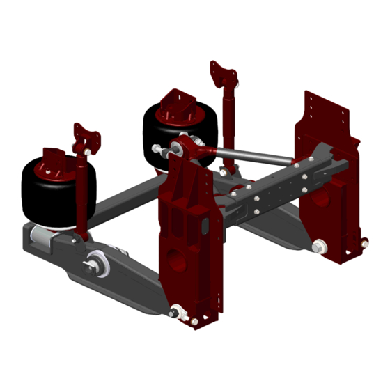
Motorhome Suspensions
RD2300 Series/RD2400 Series
Parallelogram Rear Drive Suspension
Owner's Manual
Maintenance Instructions
Document #: D707409
Revision: G
Revision Date: 05/2018
Reyco Granning Suspensions
1205 Industrial Park Drive
Mount Vernon, MO 65712
Phone: 417-466-2178
Fax: 417-466-3964
www.reycogranning.com
Service Parts
Advertisement
Table of Contents

Related Manuals for Reyco Granning RD2300 Series


Summary of Contents for Reyco Granning RD2300 Series
- Page 1 Motorhome Suspensions Owner’s Manual RD2300 Series/RD2400 Series Maintenance Instructions Service Parts Parallelogram Rear Drive Suspension Document #: D707409 Revision: G Revision Date: 05/2018 Reyco Granning Suspensions 1205 Industrial Park Drive Mount Vernon, MO 65712 Phone: 417-466-2178 Fax: 417-466-3964 www.reycogranning.com...
- Page 2 Page Intentionally Left Blank...
-
Page 3: Service Notes
Rear Drive SUSPENSION SERVICE MANUAL Service Notes This Service Manual describes the correct service and repair procedures for the ReycoGranning LLC RD2300NR series, RD2400NR series Rear Drive Suspensions. ® The information contained in this manual was current at the time of printing and is subject to change without notice or liability. -
Page 4: Section 1 Introduction
Section 1 Introduction Introduction ReycoGranning Air Suspensions has developed this service manual to aid in the ® maintenance of ReycoGranning ’s rear suspensions. ® The following table lists the various models and their respective capacities. Model Capacity RD2300NR-T 23,000 lbs RD2300NR-WR 23,000 lbs RD2400NR-WR... - Page 5 Section 1 Introduction Identification The serial number is used by ReycoGranning LLC for control purposes and should be ® referred to when servicing the suspension. The suspension model and serial number are stamped on an aluminum tag that is riveted to the curb side upper hanger weldment (See Figure 1).
- Page 6 Section 1 Introduction Hangers & Lower Control Arms Application: RD2300NR-WR, RD2400NR-WR, RD2300NR-T ITEM ITEM PART NO. DESCRIPTION PART NO. DESCRIPTION Nut 1 1/8-12 707365-02 Lower Control Arm (RH) 702516-02 Bolt 1 1/8-12 x 7 3/4 705446-01 Assembly LASSA 103003 Washer 3/4 24453-01 Coiled Spring Pin 705450-01...
- Page 7 Section 1 Introduction Kit, Hangers & Lower Control Arm K713471 Application: RD2300NR-EF, RD2400NR-EF, RD2401NR-EF ITEM ITEM PART NO. DESCRIPTION PART NO. DESCRIPTION Nut 1 1/8-12 707365-02 Lower Control Arm (RH) 702516-02 Bolt 1 1/8-12 x 7 3/4 705446-01 Assembly LASSA 103003 Washer 3/4 24453-01...
- Page 8 Section 1 Introduction Kit, Hangers and Lower Control Arms - K713639 Application: RD2400NR-600, RD2400TB-605EF ITEM ITEM PART NO. DESCRIPTION PART NO. DESCRIPTION Nut 1 1/8-12 24453-01 Coiled Spring Pin 702516-02 Bolt 1 1/8-12 x 7 3/4 705454-02 Washer 103003 Washer 3/4 2617 Plate, Serial Number 705450-01...
- Page 9 Section 1 Introduction Upper Control Arm (Barpin Joint Type) Application:RD2300NR-WR, RD2300NR-EF, RD2300NR-T ITEM QTY ITEM PART NO. DESCRIPTION PART NO. DESCRIPTION 705435-01 V-Link Bolt 1/2-13 x 1.25 717378-01 Weldment V-Link Mount (LH) Nut 1/2-13 717378-02 Weldment V-Link Mount (RH) 8455851 Washer Lock 5/8 707377-01 Cross Member Center Channel...
- Page 10 Section 1 Introduction Axle Connections Application: RD2300NR-WR, RD2300NR-EF, RD2300NR-T ITEM QTY ITEM PART NO. DESCRIPTION PART NO. DESCRIPTION K713303 Kit, Bushing, Through Bolt 104098 Washer 7/8 100122-P1 Nut, Strover 7/8-9 8223552 Bolt 7/8-9 X 5.0...
- Page 11 Section 1 Introduction Axle Connections Application: RD2400NR-WR, RD240XNR-EF ITEM QTY ITEM PART NO. DESCRIPTION PART NO. DESCRIPTION K713303 Kit, Bushing, Through Bolt 712627-040 Bolt M18-1.5 x 40...
- Page 12 Section 1 Introduction Axle Connections Application: RD2400NR-600, RD2400TB-605EF ITEM QTY ITEM PART NO. DESCRIPTION PART NO. DESCRIPTION 713349-01 Kit Hardware 712627-040 Bolt M18-1.5 x 40...
- Page 13 Section 1 Introduction Upper Control Arm – K713658 (Ball Joint Type) Application: RD2400NR-WR, RD2400NR-EF, RD2401NR-EF ITEM QTY ITEM PART NO. DESCRIPTION PART NO. DESCRIPTION 712520-01 V-Link with Ball Joint Apex Nut 1/2-13 713636-01 V-Link Mounting Bracket (LH) 89422850 Washer 5/8 .656 x 1.31 x .095 713636-02 V-Link Mounting Bracket (RH) 8455851...
- Page 14 Section 1 Introduction Upper Control Arm (Ball Joint Type) Application: RD2400NR-600, RD2400TB-605EF ITEM QTY ITEM PART NO. DESCRIPTION PART NO. DESCRIPTION 712520-01 V-Link with Ball Joint Apex Nut 1/2-13 713658-01 V-Link Mounting Bracket (LH) 89422850 Washer 5/8 .656 x 1.31 x .095 713658-02 V-Link Mounting Bracket (RH) 8455851...
- Page 15 Section 1 Introduction Ride Control (Shock & Air Spring) Application: RD2X00NR-WR,RD2X00NR-EF, RD2400NR-600, RD2401NR-EF, RD2400TB-605EF, RD2300NR-T ITEM QTY ITEM PART NO. DESCRIPTION PART NO. DESCRIPTION 707402-01 Air Spring Nut 3/4-16 706206-02 Shock Absorber 103003 Washer 3/4 706924-01 Air Spring Support Bracket 8223831 Bolt 3/4-16 x 3 1/2 89415543 Washer 1/2 .531x1.25x.100 Shock Bracket RD2X00NR-WR,...
-
Page 16: Section 2 Troubleshooting
Section 2 Troubleshooting Suspension System - General SYMPTOMS POSSIBLE CAUSES REMEDIES Tires wear out quickly or 1) Tires have incorrect pressure 1) Inflate tires to specified have uneven tread wear 2) Tires out of balance pressure Note: Wear pattern will 3) Incorrect ride height 2) Balance or replace tires indicate possible cause(s). -
Page 17: Section 3 Inspection
Section 3 Inspection General Inspection Checking the Trailing Arm Bushings for Wear Perform a thorough visual inspection of suspension ensure proper assembly and to identify broken parts NOTE: ReycoGranning recommends ® and loose fasteners each time the vehicle the use of a maintenance pit suspension is serviced. -
Page 18: Checking The Shock Absorber
Section 3 Inspection 4. Check that there Checking the Shock minimum of 1 inch clearance around Absorber the circumference of the air spring while it is energized with air NOTE: ReycoGranning recommends ® 5. Check the air spring piston for the use of a maintenance pit buildup of foreign material, remove or full vehicle lift during the... - Page 19 Section 3 Inspection Checking the V-Link Bolts and Bushings Preparation 1. Chock the front wheels to prevent vehicle movement. 2. Raise the rear of the vehicle until the wheels are off the ground 3. Support raised vehicle with safety stands WARNING: Do not place jacks or safety stands under the Trailing Arms to support...
- Page 20 Section 3 Inspection Assembly procedure for ball joint V-link to axle 1) Ensure axle(5) fixed constrained from moving with regard to frame except for rotation about axes shown 2) Place Upper Control Saddle(6.1) aligning the spigot with that of the axle by articulating axle and upper control arm(6) and the ball joint about their axes.
-
Page 21: Section 4 Maintenance
Section 4 Maintenance MAINTENANCE SCHEDULE GENERAL MILEAGE IN THOUSANDS SERVICE TO BE PERFORMED MAINTENANCE 12 24 36 48 60 72 84 96 Trailing Arm Check bolt torque Bushings Inspect for contact between control arm and mount Inspect for bushing wear Air Springs Inspect for proper clearance (1”... -
Page 22: Maintenance Record
Section 4 Maintenance MAINTENANCE RECORD Name of Owner Address of Owner Date of Purchase Name and Address of Dealer Model of Vehicle Vehicle Identification Number Suspension Model Number: Suspension Serial Number: RD230_____-____ RD240_____-____ Inspection and Maintenance Mileage Service Performed Item... -
Page 23: Section 5 Adjustments And Alignments
Section 5 Adjustments and Alignments 3. Loosen the clamp on the vertical link Adjusting Suspension of the height control linkage Ride Height 4. Adjust the length of the vertical link to achieve specified ride height The height control system on the Rear Drive Suspensions has been provided by If the ride height is less than 8.25”, chassis... - Page 24 Section 5 Adjustments and Alignments Inspection Before NOTE: Total vehicle alignment Alignment recommended when aligning the rear suspension Check the following before conducting front wheel alignment measurements. Inspection See “General Inspection” in Section 3 Wheels and Tires 1. Check that the rear tires are inflated appropriate pressure...
- Page 25 Section 5 Adjustments and Alignments 9. Following the alignment of both Rear Axle Alignment axles, it is recommended that it be driven through a short series of Measurement turns and then returned to the shop 1. Place the unloaded vehicle on a level to have the alignment rechecked, floor area after again freeing all suspension...
-
Page 26: Section 6 Repair
Section 6 Repair Drying Repairing of Parts Parts must be dried immediately after cleaning. Parts should be dried with WARNING: clean paper, rags, or compressed air. The repair or reconditioning of rear Preventing Corrosion suspension components is not allowed. ReycoGranning® Apply light oil to cleaned and dried parts recommends replacing damaged or that are not damaged and are to be... -
Page 27: Installation
Section 6 Repair Installation Installation 1. Slide the trailing arm assembly into 1. Install the shock absorber rod end to the pivot hanger the upper shock mount 2. Insert the pivot bolt with all Rey- 2. Loosely install upper shock Align components mounting hardware 3. - Page 28 Section 6 Repair Spring Support Assembly (LASSA), it Removal should be positioned such that the weld is 1. Disconnect the air line at the air within ¼” of the cross tube neutral axis. spring and remove the connection The neutral axis is at middle height of the fitting cross tube.
- Page 29 Section 6 Repair 4. Make sure the V-Link assembly is fully supported before removing the final two bolts holding it place WARNING: V-link weighs in excess of 75 lbs 5. Remove the V-Link Assembly Installation 1. Replace the V-Link in the same order in which it was removed.
-
Page 30: Torque Specifications
Section 6 Repair TORQUE SPECIFICATIONS Most threaded fasteners are covered by specifications that define required mechanical properties, such as tensile strength, yield strength, proof load, and hardness. These specifications Figure 2 – Grade Markings on Bolts carefully considered in initial selection of fasteners for a given application. - Page 31 Page Intentionally Left Blank...
Need help?
Do you have a question about the RD2300 Series and is the answer not in the manual?
Questions and answers