Table of Contents
Advertisement
Quick Links
Motorhome Suspensions
Owner's Manual
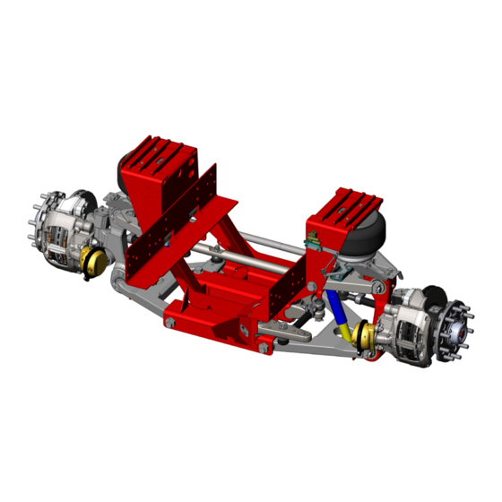
IFS1700S
| Independent Front Suspension
Maintenance Instructions
Service Parts
Document #: D711987
Revision: C
Revision Date: 9/14
1-800-753-0050
Reyco Granning Suspensions
1205 Industrial Park Drive
Mount Vernon, MO 65712
Phone: 417.466.2178
w w w . r e y c o g r a n n i n g . c o m
Fax: 833.896.6997
Advertisement
Table of Contents

Related Manuals for Reyco Granning IFS1700S


Summary of Contents for Reyco Granning IFS1700S
- Page 1 Document #: D711987 Revision: C Revision Date: 9/14 1-800-753-0050 Reyco Granning Suspensions 1205 Industrial Park Drive Mount Vernon, MO 65712 Phone: 417.466.2178 w w w . r e y c o g r a n n i n g . c o m...
-
Page 3: Table Of Contents
Inspecting the Shock Absorber ...............29 Inspecting the Air Spring and Height Control Valve ........30 Air Spring Inspection ...................... 30 Height Control Valve Inspection ..................30 Inspecting the Idler Arm & Crank Arm Bearings ...........30 Inspecting the Relay Rod Ball Joints ..............31 D711987 IFS1700S... - Page 4 Installation........................48 Replacing the Bell Crank, Idler Arm, and Crank Arm Bearings ....48 Removal .......................... 49 Installation........................49 Replacing the Upper and Lower Control Arm Bushings ........49 Upper Control Arm Removal..................50 Upper Control Arm Installation ..................50 D711987 IFS1700S...
- Page 5 Replacing the Sway Bar and Components ............57 Vertical Linkage Removal ....................57 Vertical Linkage Installation................... 57 Sway Bar Removal ......................57 Sway Bar Installation ...................... 57 Replacing the Steering Knuckle Carrier Bearings ..........58 Removal .......................... 58 Installation........................59 Torque Tables ............61 D711987 IFS1700S...
-
Page 6: Introduction
Introduction Introduction Service Notes This Service Manual describes the correct service and repair procedures for the IFS1700S Independent Front Suspension model with 17,000 lbs Gross ® Reyco Granning Axle Weight Rating (GAWR). Overloading the suspension may result in adverse ride and handling characteristics. -
Page 7: Identification
(Figure 2). Figure 1 - Suspension Identification Location Figure 2 - Suspension Serial Number Tag GAWR Wheel Disc Sway Model Height Control (lb) Brakes IFS1700S Dual Valve IFS1700S-SB Single Bendix 17,000 55° IFS1700S-SHC ADB22X Electronic... -
Page 8: Vehicle Towing Information
Do Not attach tow apparatus (hooks, chains, straps, etc.) to suspension upper and lower control arms, sway bar and brackets, brake components, tie rods, steering arm assemblies, or steering knuckle carrier assemblies (Figure 3). Figure 3 – Improper Tow Equipment Attachment Locations D711987 IFS1700S... -
Page 9: Maintenance Schedule
1. Wheel Nuts must be re-tightened to proper torque specifications as per the vehicle or chassis manufacturer’s Owner Guide 2. Continue to perform specified maintenance every 12,000 miles or at previous interval 3. Final stage manufacturer should complete toe-in inspection and adjustment after completion of vehicle D711987 IFS1700S... - Page 10 Name of Owner: Address of Owner: Date of Purchase: Name and Address of Dealer: Model of Vehicle: Vehicle Identification Number: Suspension Model Number: Suspension Serial Number: IFS1700S; IFS1700S-SB; IFS1700S-SHC; IFS1700S-SHCSB Inspection and Maintenance Item Date Mileage Service Performed D711987 IFS1700S...
-
Page 11: Parts Lists
Parts Lists Unit Assembly Item Part No. Description Item Part No. Description 711511-01 Sub frame Assembly 707819-01 Hub and Rotor Assembly 700944-01 Lower Control Arm Assembly 705951-01 Air Spring Assembly 703182-01 Upper Control Arm Assembly See Note Shock Assembly 700245-01 Boss, Eccentric 700178-06 Standard Shock (01/21/13 &... -
Page 12: Control Arm Components
Spacer 702516-02 Hex Head Bolt 1 1/8-12 x 7.75, Gr. 8, ZY Hex Head Bolt 7/8-9 x 8.50, Gr. 8, ZN Hardened Flat Washer, 1 1/8” 100122-P1 Lock Nut 7/8-9”, Gr. C Lock Nut 1 1/8-12, Gr. C D711987 IFS1700S... -
Page 13: Control Arm Assemblies
Control Arm Assemblies Item Part No. Description Item Part No. Description 703181-01 Upper Control Arm, LH & RH 8382 Bushing 700939-01 Lower Control Arm, LH & RH D711987 IFS1700S... -
Page 14: Steering Components
K705382 Kit, Ball Joint and Hardware Bearing Spacer Shaft 7348-050 Ball Joint (40mm) Friction Washer 705382-01 712869-01 1) Components of Ball Joint Kit K705382 2) Components of Bearing Replacement Kit K710622 3) Components of High Friction Pivot Shaft Kit K712871-01 D711987 IFS1700S... - Page 15 Part No. Description 103712 Tie Rod End, RH 101445-P1 Cotter Pin (Not Shown) 6632 Clamp 710671-01 Tie Rod End, LH 700971-01 Tube, Tie Rod 700971-02 Tube, Crank Rod 103736 Tie Rod End, LH 710671-02 Tie Rod End, RH D711987 IFS1700S...
-
Page 16: Air Spring And Shock Components
19 100727-P1 HHB 3/4-10 x 4.00, Gr. 8, ZN 100039-P1 HHB 3/4-10 x 2.75, Gr. 8, ZN 700184-04 HHB 5/8-18 x 1 3/4, Gr. 8, ZN Note: Contact ReycoGranning LLC with Unit Serial Number to determine Build Date & Original Shock P/N (Always replace in Pairs) D711987 IFS1700S... -
Page 17: Height Control Components
Height Control Components Item Part No. Description Item Part No. Description 5608 Height Control Valve (Standard) 703915-01 Linkage Assembly Kit 705378-01 Height Control Sensor, Electronic (SHC Model) 17.1 Height Control Linkage 90º 5/16-18 702606-02 HHB 1/4-20 x 1.25”, Gr. 8, ZN 17.2 Height Control Linkage 5-1/8”... -
Page 18: Sway Bar Components (-Sb Models Only)
702894-01 *Mount, D-Ring Sway Bar 89422299 **LN 7/16-14, Gr. 8 K705273 Kit, Sway Bar Fasteners 89422301 **LN 1/2-13, Gr. 8, Zinc 702797-01 **FHB 7/16-14 x 1.25, Gr. 8, ZP * Items included with K706842 ** Items included with K705273 D711987 IFS1700S... -
Page 19: Disc Brake Components
Lock Nut ¾-16 x .75, Gr. G, PH 705017-02 Arm, Steering, RH 103003 HFW 3/4” 705011-21 Castle Nut 1¼ - 12 708181-01 Nut, Spindle, Pro-Torq 705011-26 Key 709226-01 Hub Cap 705011-22 Assembly, Steering Stop 707819-01 Hub and Rotor Assembly 705011-20 Cotter Pin 3/16 x 2-1/2 D711987 IFS1700S... -
Page 20: King Pin Components
King Pin Components Item Part No. Description Item Part No. Description 705011-07 Shim, .005” thick 705011-17 Cap, King Pin 705011-08 Shim, .010” thick 705011-18 O-Ring 705011-09 Shim, .020” thick 705011-19 King Pin 705011-14 Assembly, Bearing, Thrust 10 705315-01 Draw Key, (Long 3.80) 705011-15 Bolt, King Pin Cap 11 705316-01 Nut, Draw Key 705011-16 Grease Fitting, Straight... -
Page 21: Steering Knuckle Carrier Components
Upper Bar Pin 702835-01 Bearing Cup 702621-01 Lower Bar Pin 702623-02 Shim, .010 702836-01 Seal 702618-01 Split Collar 702619-01 Outer Collar 702620-01 Retaining Clip 702623-01 Shim, .004 7352 Grease Zerk, Hydraulic Shutoff 11 12 Left Hand Steering Knuckle Carrier Shown D711987 IFS1700S... -
Page 22: Lubrication
Lubrication Lubrication Lubricant Specifications and Intervals COMPONENT SERVICE INTERVAL CHANGE INTERVAL LUBRICANT SPECIFICATION Multi-Purpose Chassis Grease Rod Ends of Tie Whichever comes first: Every oil Rods & Crank Rod change or every 6 months Premium Multi-Purpose Chassis Grease NLGI Grade 2 Kingpin Whichever comes first: Every oil Multi-Purpose Chassis Grease... -
Page 23: Rod Ends On Tie Rods Crank Rod
(Figure 4). knuckle kingpin housing and carrier. Grease Fittings Grease Fittings Grease Fittings Figure 4 – Location of Lubrication Fittings Note: Left side only shown D711987 IFS1700S... -
Page 24: Wheel Bearings
Wheel Bearings NOTE: The hub cap window can only be cleaned with mild soap and water. 1. Review lubricant specification and Aromatic solvents should not be used, interval requirements before servicing. as they will impair the transparency of the window. 2. -
Page 25: Troubleshooting
Obstruction with steering gear pitman arm Inspect, remove obstruction(s) and repair or or within hydraulic lines replace as required Obstruction within wheelhouse Inspect, remove obstruction(s) as required Excessive internal steering gear leakage Inspect, repair or replace as required D711987 IFS1700S... - Page 26 Steering gear valve binding Inspect, repair or replace as required Steering gear not centered Inspect and adjust as required Excessive internal steering gear leakage Inspect, repair or replace as required Excessive water puddling on road Avoid water puddles on road D711987 IFS1700S...
- Page 27 Check and repair or replace as required hard braking or ABS malfunction light remains lit ABS sensor electrical connection faulty Check ABS sensor connection and lead wire Tone ring on hub damaged Check for damage and replace as required D711987 IFS1700S...
- Page 28 Replace brake pads as required Brake Rotor Warped Re-machine or Replace as required Defective Brake Rotor Inspect for defects and Replace as required Refer to Bendix Disc Brakes manual Y006471 for troubleshooting of the disc brakes or contact Customer service at 1-800-247-2725. D711987 IFS1700S...
-
Page 29: Inspection
NOTE CAUTION It is recommended that the bushings in Reyco Granning LLC recommends all of the control arms be replaced at replacing any damaged or out-of- the same time if one is found worn. specification components. -
Page 30: Inspecting The Tie Rod Ends
(Figure 6). Be sure to only apply hand pressure to the tie rod. D711987 IFS1700S... -
Page 31: Inspecting The Abs Sensor And Tone Ring
Re-seat components as needed. 9. Inspect the tone ring on the hub for physical damage proper installation onto the hub. The tone ring should have a maximum run out of .008 inch relative to the hub/spindle centerline. D711987 IFS1700S... -
Page 32: Inspecting The Air Spring And Height Control Valve
Figure 8 - Ride Height Measurement 3. Check airlines to make sure contact Unit Ride Height “A” Air Spring “B” IFS1700S 6.61” 9.25” does not exist between the airlines and the outside diameter of the air spring. Inspecting the Idler Arm Re-secure airlines to prevent contact as &... -
Page 33: Inspecting The Relay Rod Ball Joints
2. Using a C-clamp, squeeze the Relay Rod and the steering arm assembly together to seat the ball joint. Do not apply excessive clamp load. 3. Set the dial indicator on “zero”. Figure 10 - Wheel End Play Measurement D711987 IFS1700S... -
Page 34: Inspecting The Knuckle Carrier Bearing And Seal
Measure and record the dial indicator reading. 5. If the axial endplay is more than “0” inch, then replace the carrier bearings. See repair section on knuckle carrier. Inspecting the Kingpin Vertical Endplay 1. Turn the tire straight ahead. D711987 IFS1700S... -
Page 35: Adjustments
Rotate the hub such that the 11. Back the nut off until it is loose. hub cap drain plug is facing upwards. Remove the drain plug from the hub cap and place it in a container for re- installation. D711987 IFS1700S... - Page 36 The vent plug will normally weep a small amount of oil. 18. Compress and insert the keeper arms, one at a time, into the undercut groove with a small screwdriver. 19. Verify the end play D711987 IFS1700S...
-
Page 37: Adjusting Suspension Ride Height
Height NOTE: It is recommended that the upper Unit Ride Height “A” Air Spring “B” and lower studs be positioned IFS1700S 6.61” 9.25” parallel to each other. Torque to 8- 12 ft-lb. Properly adjusted ride height results in correct suspension travel and alignment. -
Page 38: Adjusting The Maximum Wheel Turn Angle
Figure 12 - Steering Stop Bolt alignment machine to check the wheel turn Unit Steering Stop Length “A” angle. See the measurement procedure of IFS1700S 1.38” the alignment machine manufacturer. 1. Drive the front tires on a suitable The steering stop bolt on the steering device that allows the front wheels to knuckle controls the maximum turn angle. -
Page 39: Inspection Before Alignment
2. Check the suspension ride height and 7. Loosen the jam nut on the stop bolt. adjust as needed to the specified 8. Turn the stop bolt until the specified height. wheel turn angle is achieved and the bolt head contacts the knuckle carrier. D711987 IFS1700S... -
Page 40: Rear Axle And Suspension
7. Refer additional The bar pins of the knuckle carrier bearing recommendations and specifications from the manufacturer of the chassis marked with a “B” may also be used to provide additional camber adjustment. rear axles suspensions. D711987 IFS1700S... -
Page 41: Preparation
5. If adjustment to camber and caster is required then follow the steps below. Otherwise, go to the “Adjusting the Toe-In” section to adjust th e toe-in as needed. D711987 IFS1700S... -
Page 42: Adjusting The Camber Angle
Right +1/4°(±1/4°) +1/4°(±1/4°) front or rear of the vehicle (Figure 13). Camber is positive when the distance between centers of the front wheels at the top is greater than the distance at the ground. D711987 IFS1700S... - Page 43 2. Loosen the setscrews. 3. Rotate each eccentric adapter to the same orientation as needed based on measured wheel camber. The eccentric adapters at each control arm mount must have the same orientation. D711987 IFS1700S...
-
Page 44: Bar Pin Camber Adjustment
(Figure 15). adhesive. The control arm temperature must not exceed 300°F. Do not apply heat directly to the bar pin or mounting bolts. 3. Raise the jack to separate the bar pin from the control arm and re-orient it. D711987 IFS1700S... -
Page 45: Eccentric Caster Adjustment
The eccentric adapters at both lower control arm mounts must be oriented opposite each other to affect caster. Figure 16 – Lower Control Arm Movement D711987 IFS1700S... -
Page 46: Adjusting The Toe-In
Check that the the tendency of the tires to toe-out when suspension is at the proper ride height. the vehicle is driven straight ahead. 7. Re-measure caster and readjust as Incorrect toe-in can result in rapid tire needed. wear. D711987 IFS1700S... - Page 47 1/16” ± 1/32” and the overall toe-in is 1/8” ± 1/16”. Tighten tie rod clamp nuts to 50-60 ft-lb (See Torque Refer to Figure 18 Figure Table). 6for tie rod clamp orientation. Figure 18 – Tie Rod Clamps D711987 IFS1700S...
-
Page 48: Repair
These solutions will 5. Milling machining cause corrosion of the parts. component except that control arm bushing bores may be honed to remove any burrs. IFS1700S... -
Page 49: Rough Parts
Do not strike the component mating taper directly with a steel hammer. Parts can break and cause serious personal injury. Wear eye protection. 3. Disconnect the tie rod end ball stud from the mating component tapered hole using a suitable tool. D711987 IFS1700S... -
Page 50: Replacing The Relay Rod Ball Joints
Steering arm assembly may replacement bearings should be installed be removed to facilitate ball joint by pressing on the outer raceway only. removal. steering Pressing on the inner raceway will damage assembly replacement section the bearing. needed. D711987 IFS1700S... -
Page 51: Removal
The control arm mounts should race. Do not use a steel hammer to be inspected for damage. install the sleeve because bearing Both control arm bushings and mounting raceways can be damaged. hardware except eccentric adapters must D711987 IFS1700S... -
Page 52: Upper Control Arm Removal
The control arm temperature must not exceed Lower Control Arm Remov 300°F. Do not apply heat directly to 1. Place a portable jack under the knuckle the bar pin or mounting bolts. carrier to secure and support it. D711987 IFS1700S... -
Page 53: Lower Control Arm Installation
Place them Remove the control arm. in a container to prevent damage or loss. 8. Remove spacer tubes from bushings and retain for installation. D711987 IFS1700S... -
Page 54: Removal
Remove the wear ring from the spindle solvents. and discard it. 11. Inspect the inner cup (outer bearing race for the inner bearing) and outer cup in the hub for damage. Replace the bearing cups if worn or damaged. D711987 IFS1700S... -
Page 55: Installation
Do not “ram” the hub onto the seal. 13. Adjust the bearing by tightening the nut to 100 ft-lb. Spin the wheel at least one full rotation. 14. Repeat step #12 two more times D711987 IFS1700S... - Page 56 23. Check oil level through the hub cap window. (Figure 19). If level is below the “add” level line, then ll with recommended oil until “full” level is achieved. Add oil slowly since the heavy weight oil will settle slowly in the hub. D711987 IFS1700S...
-
Page 57: Replacing Brake Components
2. Press sensor out of steering knuckle. 9. Connect the sensor lead wire to the Do not pull sensor out by its lead wire. chassis. Secure wire lead to prevent damage during suspension movement. D711987 IFS1700S... -
Page 58: Tone Ring Removal And Installation
Table). Tighten lower shock bracket 6. Inflate the air spring by un-securing mounting bolts to 30-40 ft-lb (See horizontal Torque Table). reconnecting the vertical linkage to it. 4. Tighten upper mounting nut to 170- 190 ft-lb (See Torque Table). D711987 IFS1700S... -
Page 59: Replacing The Height Control Valve
3. Remove the “D” rings and bushings the mounting nuts to 7-9 ft-lb (See from the sway bar. Torque Table). Sway Bar Installation 3. Connect airlines as marked during removal. 1. Replace the “D” ring bushings. D711987 IFS1700S... -
Page 60: Replacing The Steering Knuckle Carrier Bearings
11. Clean the remaining grease from the charge in the shock absorber. A bearing cavity. portable jack may be needed to align the lower control arm with the knuckle carrier bar pin. D711987 IFS1700S... -
Page 61: Installation
10. Use a “feeler” gage to measure the gap between the split collar and shoulder of the groove in the bar pin. Record measurement. 11. Remove the load. Then remove the split collar and spacer. D711987 IFS1700S... - Page 62 This page intentionally left blank. D711987 IFS1700S...
-
Page 63: Torque Tables
Torque Tables Torque Tables Most threaded fasteners are covered by specifications that define required mechanical properties, such as tensile strength, yield strength, proof load, and hardness. These specifications are Grade Markings on Bolts carefully considered in initial selection of fasteners for a given application. Grade Lock Nut Lock Nut:... - Page 64 3/4-16 Grade 8 290-320 Cap Screws Driver Side Hub Cap Bolt 5/16-18 Grade 5 20-30 450-500 M22x1.5 Wheel Nut (Hub Piloted) (Dry Threads) 1) Torque applied to bolt head 2) Recheck Wheel Nut torque after first 50-100 miles D711987 IFS1700S...
- Page 65 1-800-753-0050 Mount Vernon 1205 Industrial Park Drive Mount Vernon,MO 65712 (800) 753.0050, Fax 833.896.6997 w w w. r e y c o g r a n n i n g . c o m...
Need help?
Do you have a question about the IFS1700S and is the answer not in the manual?
Questions and answers